Table of Contents
Advertisement
Quick Links
Advertisement
Table of Contents
Troubleshooting

Related Manuals for Covidien Puritan Bennett 540


Summary of Contents for Covidien Puritan Bennett 540
- Page 1 Puritan Bennett 540™ Ventilator User’s Manual...
- Page 2 Copyright information Copyright 2009 Nellcor Puritan Bennett LLC. All rights reserved. Puritan Bennett 540™ is a trademark of Nellcor Puritan Bennett LLC and/or its affiliates. COVIDIEN, COVIDIEN with Logo and ™ marked brands are trademarks of Covidien AG or an affiliate.
-
Page 3: Table Of Contents
Connecting to an External DC Power Source ........4–5 Puritan Bennett 540™ Ventilator User’s Manual... - Page 4 Pneumatic ..............A–12 Puritan Bennett 540™ Ventilator User’s Manual...
- Page 5 ................Index–7 Puritan Bennett 540™ Ventilator User’s Manual...
- Page 6 This page intentionally blank...
- Page 7 Puritan Bennett 540™ Portable Ventilator ........
- Page 8 This page intentionally blank...
- Page 9 List of Circuits..............E–2 Puritan Bennett 540™ Ventilator User’s Manual...
- Page 10 This page intentionally blank...
-
Page 11: Preface
Bennett. Extended Service The Puritan Bennett 540™ Portable Ventilator offers extended service contracts/warranties for purchase when the ventilator is purchased. Please contact your local Covidien/Puritan Bennett Sales or Service Representative for additional information. Preface-1 Puritan Bennett 540™ Ventilator User’s Manual... - Page 12 540™ Ventilator and other Puritan Bennett products 24 hours a day, 7 days a week. If you require further assistance, contact your local Puritan Bennett representative or call Puritan Bennett Technical Support at 1.800.255.6774. Preface-2 Puritan Bennett 540™ Ventilator User’s Manual...
-
Page 13: Safety Information
Indicates points of particular emphasis, that make operation of the ventilator more efficient or convenient. It is essential to read, understand and follow these instructions before using the Puritan Bennett 540™ Ventilator. In order to use the ventilator correctly and efficiently and to help prevent incidents, please pay particular atten- tion to sections 1.2,... -
Page 14: Warnings
Refer to chapter “Cleaning”. • Handle the ventilator with care during and after use, particularly when room temperatures are high. Some ventilator surfaces may become hot, even if safety specifications are not exceeded. Puritan Bennett 540™ Ventilator User’s Manual... - Page 15 This classification and regulatory requirements may vary depending upon the country and mode of transport. In addition, air transport of the Puritan Bennett 540™ Ventilator is only allowed as carry-on baggage, which may include up to two (2) individually packaged spare Lithium-ion batteries.
- Page 16 Batteries should be disposed of according to environmental legislation in your country and locality. • Never expose any batteries to direct flame. • Never touch the ventilator’s internal components, including the battery, and the patient simultaneously. Puritan Bennett 540™ Ventilator User’s Manual...
- Page 17 When using non-invasive ventilation (niv), use a non-vented nose or face mask. • Before using the Nurse Call system, ensure that its connections are secure and it operates properly. For more information, contact Puritan Bennett. Puritan Bennett 540™ Ventilator User’s Manual...
- Page 18 A continuous alarm condition will be activated if the ventilator power switch is turned off while ventilation is in progress. When the power switch is turned back on again, the ventilation will resume without having to press the VENTILATION ON/OFF button. Puritan Bennett 540™ Ventilator User’s Manual...
- Page 19 (see section 10, “Routine Maintenance in the Clinician’s Manual). This is particularly important when the ventilator is installed on a wheelchair, because environmental conditions may cause the filter to become dirty more rapidly. Puritan Bennett 540™ Ventilator User’s Manual...
- Page 20 • The Puritan Bennett 540™ Ventilator does not include an oxygen analyzer. Always measure the delivered oxygen with a calibrated oxygen analyzer that features a high and low concentration alarm in order to ensure that the prescribed oxygen concentration is delivered to the patient.
-
Page 21: Cautions
General Precautions For Use Caution • To ensure proper servicing and avoid the possibility of physical injury to personnel or damage to the ventilator, only qualified personnel should attempt to service the Puritan Bennett 540™ Portable Ventilator. General Precautions For Installation Caution Environment: •... -
Page 22: Symbols And Markings
Symbols and Markings Table 1-1. Ventilator Symbols Symbols Descriptions It is essential to read, understand, and follow these instructions before using the Puritan Bennett 540™ Ventilator (ISO 7000-0434A). This symbol appears on the ventilator’s back panel, and internal battery; see Table 1-2, item 11. - Page 23 Figure 4-9 on page 4-9. Oxygen inlet. This marking appears on the back panel of the ventilator, adjacent to the oxygen inlet port; Figure 1-4, item 3, and Figure 4-14 on page 4-14. 1-11 Puritan Bennett 540™ Ventilator User’s Manual...
- Page 24 Preferences menu. WEEE (Waste Electrical and Electronic Equipment). This symbol means that this product must not be disposed of with household waste. Observe local ordinances for proper disposal. Refer to Table 1-2, item 6. 1-12 Puritan Bennett 540™ Ventilator User’s Manual...
-
Page 25: Labels / Identification And Instruction Information
Use the item numbers in the following tables to locate the labels in Figure 1-1 through Figure 1-5. 1-13 Puritan Bennett 540™ Ventilator User’s Manual... -
Page 26: Ventilator Labels And Markings
5. Exhalation Limb 6. Air Inlet Label 7. Exhaled Gas Outlet Label Connection of Patient Circuit – (Figure 1-4) (Figure 1-2, Figure 1-4) Single Use Exhalation Block Label (Figure 1-1, Figure 1-2, Figure 1-5) 1-14 Puritan Bennett 540™ Ventilator User’s Manual... - Page 27 19. AC Mains Warning (Located Inside Connector Marking 18. ESD (Located inside the Device) the Device) (Figure 1-4) Note: The item number callouts in the following figures refer to those listed in Table 1-2. 1-15 Puritan Bennett 540™ Ventilator User’s Manual...
-
Page 28: Figure 1-1. Locations Of Labels - Top-Front View
Safety Information Figure 1-1. Locations of Labels – Top-Front View Figure 1-2. Locations of Labels – Front-Left View 1-16 Puritan Bennett 540™ Ventilator User’s Manual... -
Page 29: Figure 1-3. Location Of Labels - Front-Right View
Labels / Identification and Instruction Information Figure 1-3. Location of Labels – Front-Right View Figure 1-4. Location of Labels and Markings – Back-Left View 1-17 Puritan Bennett 540™ Ventilator User’s Manual... -
Page 30: Figure 1-5. Location Of Labels - Bottom-Front View
Safety Information NOTE: To view labels (items 11 and 14), Battery Cover and Internal Battery must be removed. Refer to section 6.6, “Replacing the Battery. ” Figure 1-5. Location of Labels – Bottom-Front View 1-18 Puritan Bennett 540™ Ventilator User’s Manual... -
Page 31: Ventilator Overview
Nurses • Home care providers • Patient and patient’s families For more details on the knowledge and skill requirements for operating the Puritan Bennett 540™ Ventilator Ventilator, refer to Appendix A, “Patient/Caregiver Checklist” in the Clinician's Manual. WARNING Federal law restricts this device to sale by or on the order of a licensed physician. -
Page 32: Operational Use
Ventilator Overview Operational Use The Puritan Bennett 540™ Ventilator uses a micro-turbine and the patient circuit with integral exhalation valve to provide ventilatory support to patients. Clinicians may use a variety of interfaces to connect patients to the ventilator: nasal or full face masks; endotracheal or tracheotomy tubes. -
Page 33: Front Panel
Exhaled Gas Outlet– Exhalation Valve connects monitoring proximal patient pressure. here. a. If exhaled volume monitoring is required, use the double-limb circuit for exhaled tidal volume or minutes volume monitoring. Figure 2-1. Front Panel Puritan Bennett 540™ Ventilator User’s Manual... -
Page 34: Back Panel
USB functionality to allow for system upgrades. AC power cable. Not currently used. Access cover for the internal battery. Air Inlet Filter: Filters air as it enters the ventilator. DC power cable connector with key. Figure 2-2. Back Panel Puritan Bennett 540™ Ventilator User’s Manual... -
Page 35: Control Panel
DC POWER indicator lit: DC power source connected. • Access to a sub-menu. • INTERNAL BAT indicator lit continuously: Ventilator powered by internal battery (no external power source connected.) • INTERNAL BAT indicator flashing: battery charging. Figure 2-3. Control Panel Puritan Bennett 540™ Ventilator User’s Manual... -
Page 36: Ventilation Menu
I:E ratio when the patient actively triggers a Refer to chapter 3, “Alarms and breath. Troubleshooting” for details. Figure 2-4. Ventilation Menu Display Puritan Bennett 540™ Ventilator User’s Manual... -
Page 37: Alarm Menu
Detected symbol appears date and end-of-event adjacent to the monitored I:E time. ratio when the patient actively triggers a breath. Refer to chapter 3, “Alarms and Troubleshooting” more information. Figure 2-5. Alarm Menu Puritan Bennett 540™ Ventilator User’s Manual... -
Page 38: Waveforms Menu
Keep in mind that troubleshooting information is available in this manual to assist you in the event of a problem. Refer to chapter 3, “Alarms and Troubleshooting”. If you cannot determine the cause of a problem, contact your equipment supplier or Puritan Bennett. Puritan Bennett Technical Services (USA): 1-800-255-6774 Puritan Bennett 540™ Ventilator User’s Manual... -
Page 39: Alarms And Troubleshooting
3 Alarms and Troubleshooting WARNING Setting Alarm limits to extreme values can cause the ventilator alarms to malfunction. The alarms or faults generated by your Puritan Bennett 540™ Ventilator are classified into two categories: • Ventilation (or utilization) alarms •... -
Page 40: Alarm Display
There are currently no Low Priority (LP) Alarms. When an alarm is triggered, if the current menu displayed is not the Ventilation parameters or Alarm menu, the display automatically switches to one of these menus to display the alarm message. Puritan Bennett 540™ Ventilator User’s Manual... -
Page 41: Alarm Logs Menu
The display appears as follows: 3. Press the ENTER key. The Alarm Logs screen is displayed. Note: When no alarm has been activated, “NO DATA” is displayed on the screen (see graphic below). Puritan Bennett 540™ Ventilator User’s Manual... -
Page 42: Silencing The Audible Portion Of Alarms
Note: Only qualified service personnel may access all alarms and events recorded by the ventilator. Qualified personnel should refer to the Puritan Bennett 540™ Service Manual for further information. Silencing the Audible Portion of Alarms You may silence the audible portion of alarms for 60 seconds at a time. This is referred to as the Audio Paused function. -
Page 43: Resetting/Pausing Alarms
The High Pressure alarm must be manually reset. Refer to section 3.7, “Overview of Alarms, ” on page 3- To manually reset the High Pressure Alarm, proceed as follows: Press the ALARM CONTROL key twice. • The visual alarms will be reset. Puritan Bennett 540™ Ventilator User’s Manual... -
Page 44: Re-Activating Alarms
• The messages of all active alarms are displayed in a loop in the Ventilation and Alarm menus. • The Audio Paused symbol disappears (if it was displayed). • The Alarm Paused symbol disappears. Puritan Bennett 540™ Ventilator User’s Manual... -
Page 45: Overview Of Alarms
Consequence: battery charging *IF PERSISTS stops. REPLACE VENT Failure of one calibration point of the internal exhaled flow sensor. CAL FAULT Consequence: failed calibration SEE USER MNL point is replaced by the default point. Puritan Bennett 540™ Ventilator User’s Manual... - Page 46 CHECK Consequence: SETTINGS • Locking Key disabled • Out-of-range settings are replaced by their default values CHK EXH VALV RESTART VENT* • Faulty pressure valve sensor signal at ventilation start. *IF PERSISTS REPLACE VENT Puritan Bennett 540™ Ventilator User’s Manual...
- Page 47 Detection of a fault in sensor DEVICE FAULT7 voltage measurement. REPLACE VENT Inspiratory flow is constant (+/- 1 lpm) with normal turbine DEVICE FAULT8 temperature and speed REPLACE VENT conditions. Contact your service representative for assistance. Puritan Bennett 540™ Ventilator User’s Manual...
- Page 48 HIGH INSP VOLUME Alarm activation occurs: • After three consecutive breaths. Minute volume higher than High MinVol set during three consecutive breaths. HIGH MINUTE Alarm activation occurs: VOLUME • After three consecutive breaths. 3-10 Puritan Bennett 540™ Ventilator User’s Manual...
- Page 49 LOW BATTERY < 30 min. or 5%. Expired tidal volume less than Low VTE set during three consecutive breaths (in double- limb setup). LOW EXH VOLUME Alarm activation occurs: • After three consecutive breaths. 3-11 Puritan Bennett 540™ Ventilator User’s Manual...
- Page 50 Alarm activation occurs: *IF PERSISTS • REPLACE VENT After three consecutive breaths. Cut-off of the external DC power ON INTERNAL supply. BATTERY Consequence: switch-over to (with Periodic the internal battery. Audible Signal) 3-12 Puritan Bennett 540™ Ventilator User’s Manual...
- Page 51 Contact your SPKR FAULT3 service representative for REPLACE VENT assistance. Buzzer Battery Failure. The Battery Buzzer Voltage is too SPKR FAULT4 low, disabling the buzzer. REPLACE VENT Contact your service representative for assistance. 3-13 Puritan Bennett 540™ Ventilator User’s Manual...
-
Page 52: Troubleshooting
• To ensure proper servicing of the ventilator and reduce the possibility of physical injury, only qualified personnel should attempt to service the Puritan Bennett 540™ Ventilator. 3.8.1 Alarms WARNING When an alarm condition is triggered, or there is evidence of a patient-ventilator fault or problem, examine the patient first before examining the ventilator. - Page 53 BATT FAULT4 Battery charging impossible. cannot be involuntarily disconnected. REPLACE VENT In the event the internal battery capacity is low, use an alternate device to ventilate the patient. Call your customer service representative. 3-15 Puritan Bennett 540™ Ventilator User’s Manual...
- Page 54 EXH VALVE1 * phase. Have a qualified technician replace the *IF PERSISTS Contaminated or defective expiratory flow defective component(s) and call your REPLACE VENT sensor. customer service representative. 3-16 Puritan Bennett 540™ Ventilator User’s Manual...
- Page 55 Reminder: the internal battery can be overextended. charged only when the ventilator connected to an AC power supply. Check and properly connect the patient EXHSENS FAULT OR Leak in the patient circuit. circuit connections. CIRCUIT FAULT 3-17 Puritan Bennett 540™ Ventilator User’s Manual...
- Page 56 Treat patient’s cough. Patient inspiratory resistance or Have physician determine new ventilator compliance changes. settings. Defective internal circuits of the machine or Replace the ventilator and call your pressure sensor. customer service representative. 3-18 Puritan Bennett 540™ Ventilator User’s Manual...
- Page 57 Replace the defective component(s) and Defective expiratory flow sensor. Call your customer service representative or clinician. Under the guidance of a Clinician modify Adjustment of the Low VTE level too high. the Low VTE level. 3-19 Puritan Bennett 540™ Ventilator User’s Manual...
- Page 58 Replace the ventilator and call your Ventilator’s current-limiting fuse blown. customer service representative. Internal problem in the electrical power Replace the ventilator and call your POWER FAULT supply. customer service representative. REPLACE VENT 3-20 Puritan Bennett 540™ Ventilator User’s Manual...
-
Page 59: Other Problems
Replace the ventilator and call your Internal technical problem that prevents SPKR FAULT4 customer service representative. the battery warning buzzer from operating. REPLACE VENT 3.8.2 Other Problems Table 3-3 provides other possible ventilator problems, causes, and corrective actions. 3-21 Puritan Bennett 540™ Ventilator User’s Manual... -
Page 60: Table 3-3. Additional Problems And Corrective Actions
Remove obstructions from all blocked Excessive heat inlets of the casings. ventilator air inlets and outlets. emitted Replace the ventilator and call your Condensation Liquid entered the device. customer service representative. inside the device 3-22 Puritan Bennett 540™ Ventilator User’s Manual... -
Page 61: Installation And Assembly
The use of a bacterial filter at the ventilator’s outlet—or both ports if a double-limb circuit is used—is recommended. Installing the Ventilator To install your Puritan Bennett 540™ Ventilator correctly we recommend that you proceed in the following manner: •... -
Page 62: Connecting To External Ac Power
The use of any accessory other than those specified by Puritan Bennett, may lead to an increase in electromagnetic emissions or a decrease in the equipment’s insulation against electromagnetic emissions. • The Puritan Bennett 540™ Ventilator requires special precautions for electromagnetic compatibility and should be installed and started according to the recommendations stated in Appendix A, “Specifications”. -
Page 63: Figure 4-2. Inserting The Power Cable Holder Into The Notch
The only time the AC POWER and INTERNAL BAT indicators are illuminated at the same time is when the ventilator is connected to an AC supply and the battery is charging (INTERNAL BAT indicator is flashing). Puritan Bennett 540™ Ventilator User’s Manual... - Page 64 2. Disconnect the AC power cable from the ventilator’s AC connector at the rear of the device. 3. Grasp the AC power cable at the level of the power cable holder and turn the cable counterclockwise while lifting it upwards and out of the holder. Puritan Bennett 540™ Ventilator User’s Manual...
-
Page 65: Connecting To An External Dc Power Source
Connect the external DC power source by first connecting the power cable to the ventilator and then to the external DC source. Follow the reverse procedure to disconnect the device from the external DC power source. Puritan Bennett 540™ Ventilator User’s Manual... -
Page 66: Patient Circuit
The ventilator and patient circuit should always be placed so as to provide a secure, comfortable fit for the patient. • The patient circuit should always be positioned to avoid hindering the patient's movements, to prevent accidental disconnection, and to minimize the risk of patient strangulation. Puritan Bennett 540™ Ventilator User’s Manual... -
Page 67: Choosing The Patient Circuit Type
Always assure that the patient is receiving the appropriate inspired volume when altering the breathing circuit configuration. • Users must always possess an additional circuit and valve while using the Puritan Bennett 540™ Ventilator. 4.4.1 Choosing the Patient Circuit Type Single limb circuits are used with breathing modes where spirometry measurements are not required, and double limb circuits are used with breathing modes where spirometry is required. - Page 68 8. Ensure that the water trap (item 3) on the expiratory limb of the patient circuit (item 7) is securely installed between the patient wye (item 5) and the exhalation valve (item 9). Puritan Bennett 540™ Ventilator User’s Manual...
-
Page 69: Figure 4-9. Close-Up Of Exhalation Valve Tube And Proximal Pressure Tube
LOW PRESSURE DISCONNECT triggering threshold by doing one of the following: set the high VTI alarm limit for pressure modes or set low VTE alarm limit for all ventilation modes if using a dual limb circuit. Puritan Bennett 540™ Ventilator User’s Manual... -
Page 70: Filters
Air Inlet Filter Consisting of foam and fine particle filter media and located at the rear of the ventilator, this filter cleans the air as it enters the ventilator. Refer to the figure below. 4-10 Puritan Bennett 540™ Ventilator User’s Manual... -
Page 71: Humidifier
4-12) adds moisture (water vapor) and warms the air in the patient circuit. It is inserted into the patient circuit between the main outlet and the patient (refer to Figure 4-7 Figure 4-8). 4-11 Puritan Bennett 540™ Ventilator User’s Manual... -
Page 72: Exhalation Block
• Each time an exhalation block is installed, the expiratory flow sensor must be recalibrated before using the ventilator. Caution Ensure that the exhalation block has been completely dried after it is cleaned. 4-12 Puritan Bennett 540™ Ventilator User’s Manual... -
Page 73: Oxygen
Since the factors that affect administered oxygen flow may change over time, you must ensure that these settings always correspond to the current oxygen therapy objectives specified by the physician. Note: To monitor patient Oxygen levels use an external sensor/alarm. 4-13 Puritan Bennett 540™ Ventilator User’s Manual... -
Page 74: Connecting The Oxygen Supply
Inspect the oxygen coupler (Figure 4-15, item 2) before use to ensure it has its black O-ring attached and in good condition. Do not use an oxygen coupler with a missing, damaged, or worn O-ring. 4-14 Puritan Bennett 540™ Ventilator User’s Manual... -
Page 75: Figure 4-15. Connecting The Oxygen Supply System
3. Disconnect the oxygen supply’s oxygen connector by pulling it towards you. The ventilator’s oxygen connector’s locking stud (Figure 4-15, item 2) will then extend outwards, which is required before the oxygen connector can be reconnected. 4-15 Puritan Bennett 540™ Ventilator User’s Manual... -
Page 76: Mounting The Ventilator On A Wheelchair
Thoroughly air the room to bring the oxygen concentration down to normal. • To prevent any interference with the internal sensors of the Puritan Bennett 540™ Ventilator, do not install a humidifier upstream of the ventilator. Caution •... -
Page 77: Mounting The Ventilator On The Utility Cart
Before using the ventilator on the internal battery, ensure that it is charged and that the charge holds (refer to chapter 6, “Internal Battery”). The Dual Bag accessory consists of a carrying bag that allows the Puritan Bennett 540™ Ventilator to be both mounted onto a wheelchair and carried as a backpack (see Figure 4-17). -
Page 78: Connecting The Nurse Call Cable
Puritan Bennett. Caution • To connect the Puritan Bennett 540™ Ventilator to a nurse call device, first contact Puritan Bennett to verify device compatibility and to obtain a suitable connection cable. • Do not use Nurse Call devices that operate based on the closure of an electrical circuit, because the devices often do not take into account possible cable disconnection or a total loss of power. - Page 79 A remote alarm is activated when an alarm condition occurs, unless either of the following is true: • The audio paused function is active. • The ventilator power switch is OFF. • The remote alarm port is an 8-pin female connector; allowable current is 100mA at 24VDC(max). 4-19 Puritan Bennett 540™ Ventilator User’s Manual...
- Page 80 Installation and Assembly This page intentionally blank 4-20 Puritan Bennett 540™ Ventilator User’s Manual...
-
Page 81: Operating Procedures
Turning on The Ventilator Caution After storage of the Puritan Bennett 540™ Portable Ventilator in an atmosphere that differs significantly in temperature from where it is installed—typically, ± 36 °F (20 °C)—stabilize the device at room temperature for at least two (2) hours prior to starting it. -
Page 82: Starting Ventilation
Starting Ventilation Before starting ventilation, refer to Appendix B, “Operational Verification Checklist”, and set the parameter values in the Preferences menu. Puritan Bennett 540™ Ventilator User’s Manual... - Page 83 The blue light indicator, at the upper right of the VENTILATION ON/OFF (see Figure 5-4, item 2), turns off. • A “beep“ sounds. • The ventilation starts. • The values of the monitored parameters are displayed in the right-hand window. Puritan Bennett 540™ Ventilator User’s Manual...
-
Page 84: Stopping Ventilation
1. Hold down the VENTILATION ON/OFF (Figure 5-4, item 1) for about three (3) seconds. • A message prompting the user to keep the button pressed appears on the monitoring window, as shown in the graphic below: Puritan Bennett 540™ Ventilator User’s Manual... -
Page 85: Turning Off The Ventilator
AC POWER indicator is illuminated), the internal battery continues charging. WARNING Handle the ventilator with care after use, particularly when room temperatures are high. Some ventilator surfaces may be very hot, even if safety specifications are not exceeded. Puritan Bennett 540™ Ventilator User’s Manual... - Page 86 Operating Procedures This page intentionally blank Puritan Bennett 540™ Ventilator User’s Manual...
-
Page 87: Internal Battery
6 Internal Battery WARNING • Because the internal battery of the Puritan Bennett 540™ Ventilator contains more than 8 grams (equivalent) lithium, it is categorized as Dangerous Goods (DG) Class 9—even though the ventilator meets current safety standards. The ventilator, because of this categorization, is subject to strict transport conditions under the... -
Page 88: Battery Operation
• Battery reserve capacity is displayed on the right of the symbol. • The “ “ indicator at the top left of the ventilator’s front panel is continuously lit INTERNAL BAT (Figure 6-1). Puritan Bennett 540™ Ventilator User’s Manual... - Page 89 If the ventilator is running, the internal battery reserve is momentarily displayed as a percentage. Then, after the ventilator calculates the battery time remaining (which takes about two minutes, Puritan Bennett 540™ Ventilator User’s Manual...
-
Page 90: Testing The Battery
Recharging the Battery In the event that the battery charge level is considered insufficient, as per the reserve capacity display, recharge of the internal battery is necessary. In general, it is recommended that the ventilator be Puritan Bennett 540™ Ventilator User’s Manual... -
Page 91: Storing The Battery
If the device is to be stored for an extended period of time, it is not necessary to remove the battery. However, the battery should be stored in cool, dry, well-ventilated environment, as follows: Puritan Bennett 540™ Ventilator User’s Manual... -
Page 92: Replacing The Battery
You remove the protective “pull tabs” (if they are present) from the battery’s contacts. • The battery’s contacts align with those of the ventilator, according to the drawing on the label on the back of the battery cover. Puritan Bennett 540™ Ventilator User’s Manual... - Page 93 7. Install the three Torx screws (Figure 6-3, item 1) to secure the battery cover (Figure 6-3, item 2) to the ventilator and tighten the screws with the Torx T10 screwdriver. Puritan Bennett 540™ Ventilator User’s Manual...
- Page 94 This page intentionally blank...
-
Page 95: Cleaning
Table 7-1. Approved Cleaning Solutions for Exterior Ventilator Surfaces Description Product Names Tap water – Saline – Mild dishwashing detergent Joy® (or equivalent) 70% isopropyl alcohol (rubbing alcohol) – 10% chlorine bleach (90% tap water) Clorox® (or equivalent) Puritan Bennett 540™ Ventilator User’s Manual... -
Page 96: Cleaning The Accessories
Caution Never use a liquid cleaner inside the patient circuit, or on any component of a gas or air pathway. Puritan Bennett 540™ Ventilator User’s Manual... -
Page 97: Routine Maintenance
The fine particle side of the filter faces outwards, away from the ventilator. b. The filter is properly installed in its housing. Proper installation of the filter prevents particles from entering the device. Puritan Bennett 540™ Ventilator User’s Manual... -
Page 98: Recommended Schedule Of Maintenance
See manufacturer’s recommendation Exhalation Block 3 months (for each new patient) Note: For more information regarding parts and accessories for the Puritan Bennett 540 Ventilator contact your service representative or www.puritanbennett.com. WARNING • Regularly check the cleanliness of the air inlet filter located on the rear of the ventilator. Replace it when necessary—even before the recommended replacement period has elapsed, and particularly... -
Page 99: Service Assistance
Puritan Bennett. Corporate Address: Technical Service Phone Numbers: Covidien Troubleshooting your portable ventilator: 1-800-255-6774 6135 Gunbarrel Avenue Servicing your portable ventilator: 1-800-255-6774 Boulder, CO 80301 U.S.A. Puritan Bennett 540™ Ventilator User’s Manual... - Page 100 Routine Maintenance This page intentionally blank Puritan Bennett 540™ Ventilator User’s Manual...
-
Page 101: A Specifications
Maximum allowable flow resistance: 4cmH2O at Requirement 60 lpm Electrical Table A-2. AC Electrical Supply Voltage Frequency Consumption 100 VAC to 240 VAC 50 Hz / 60 Hz 180 VA max. 12 VDC 8.3 A 30 VDC 3.3 A Puritan Bennett 540™ Ventilator User’s Manual... -
Page 102: Indicators And Alarms
The remote alarm port is an 8-pin female remote supply -(not connector. Allowable current is 100 mA at used) 24 VDC (maximum). RX Signal (not used) TX Signal (not used) remote supply +(not used) not used Indicators and Alarms Puritan Bennett 540™ Ventilator User’s Manual... -
Page 103: Performance
Table A-9. Volume Performance Test Results R-Rate (bpm) Insp Time VTI min. (ml) C50 R5 VTI max. (ml) 2000 2000 1750 1200 VTI min. (ml) C20 R20 VTI max. (ml) 1000 VTI min. (ml) C20 R20 VTI max. (ml) Puritan Bennett 540™ Ventilator User’s Manual... -
Page 104: Monitored Parameters
Expiratory Minute Volume (Min VE) 0 to 99.9 l +/- (20ml + 20%) in CPAP mode above 200ml a. The PB 540 does not have the capability to reduce pressure below the PEEP pressure during the expiratory phase. Puritan Bennett 540™ Ventilator User’s Manual... -
Page 105: Range, Resolution, And Accuracy
Accuracy: +/- (4 lpm +10%) of target exhalation flow based on Exh Sense Default value: 25% In CPAP, V SIMV, and P SIMV, Exh Sens is fixed at 25% and is not adjustable. Ventilator Settings (Cont’d) Puritan Bennett 540™ Ventilator User’s Manual... - Page 106 Default value: 300 Depends on: High VTI High Inspired Tidal Volume Range: 80 mL to 3000 mL (High VTI) Resolution: 10 mL Default value: 2000 mL Depends on: Low VTI Pressure A/C Mode (Cont’d) Puritan Bennett 540™ Ventilator User’s Manual...
- Page 107 Resolution: 10 mL Default value: OFF Depends on: High VTE High exhaled tidal volume Range: 80 mL to 3000 mL (High VTE) Resolution: 10 mL Default value: OFF Depends on: Low VTE PSV/CPAP Mode (Cont’d) Puritan Bennett 540™ Ventilator User’s Manual...
- Page 108 Default value: OFF Depends on: Vt, High VTI High Inspired Tidal Volume Range: 80 mL to 3000 mL (High VTI) Resolution: 10 mL Default value: 2000 mL Depends on: Vt, Low VTI V SIMV Mode (Cont’d) Puritan Bennett 540™ Ventilator User’s Manual...
- Page 109 Resolution: 10 mL Default value: OFF Depends on: High VTE High Exhaled Tidal Volume Range: 80 mL to 3000 mL (High VTE) Resolution: 10 mL Default value: OFF Depends on: Low VTE P SIMV Mode (Cont’d) Puritan Bennett 540™ Ventilator User’s Manual...
- Page 110 Default value: OFF Depends on: Vt, Low VTE Low Minute Volume Range: 0.5 L to 50 L (Low Min Vol) Resolution: 0.5 L Default value: OFF Depends on: Vt, R-Rate, High Min vol A-10 Puritan Bennett 540™ Ventilator User’s Manual...
- Page 111 Resolution: 0.1 s Accuracy: ± 50 ms or 5%, whichever is greater Expiratory time (E time) Range: 0 s to 59.9 s Resolution: 0.1 s Accuracy: ± 50 ms or 10%, whichever is greater A-11 Puritan Bennett 540™ Ventilator User’s Manual...
-
Page 112: Environmental
0.057 cmH O (5.6 pascals) at 24 lpm flow a. All testing conducted on 3-inch diameter test piece Table A-17. Oxygen Inlet Specifications Maximum pressure Maximum flow 7.25 psi (50 kPa) 15 lpm A-12 Puritan Bennett 540™ Ventilator User’s Manual... -
Page 113: Manufacturer's Declaration
Table A-19. Electromagnetic Emissions The Puritan Bennett 540™ Ventilator is intended for use in the electromagnetic environment specified below. The customer or the user of the ventilator should assure that it is used in such an environment. -
Page 114: Table A-20. Electromagnetic Immunity
IEC 61000-4-8 or hospital environment. Note: U is the AC mains voltage prior to application of the test level. A-14 Puritan Bennett 540™ Ventilator User’s Manual... -
Page 115: Table A-21. Electromagnetic Immunity - Conducted And Radiated Rf
, should be less than the compliance level in each frequency range Interference may occur in the vicinity of equipment marked with the following symbol: A-15 Puritan Bennett 540™ Ventilator User’s Manual... -
Page 116: Table A-22. Recommended Separation Distances
Legendair XL2 should be observed to verify normal operation. If abnormal performance is observed, additional measures may be necessary, such as reorienting or relocating the Puritan Bennett 540™. Over the frequency range 150 kHz to 80 MHz, field strengths should be less than 10 V/m. -
Page 117: Standards Compliance And Iec Classification
Lung Ventilators for Medical Use- Particular Requirements for Basic Safety and Essential Performance Part 2: Home Care Ventilators for Ventilator-Dependent Patient ISO10651-2 2004. • Standard Specification for Ventilators Intended for Use in Critical Care ASTM F 1100 1997. A-17 Puritan Bennett 540™ Ventilator User’s Manual... - Page 118 Specifications This page intentionally blank A-18 Puritan Bennett 540™ Ventilator User’s Manual...
-
Page 119: B Operational Verification Checklist
Perform the Functioning Alarms Test. Pass Verify the alarm volume is adapted to the patient environment. Pass Ensure that you know how to charge the internal battery. Refer to Pass chapter 6, “Internal Battery”. Puritan Bennett 540™ Ventilator User’s Manual... - Page 120 If exhaled volume monitoring is required, use the Pass double-limb circuit for exhaled tidal volume or minute volume monitoring. Puritan Bennett 540™ Ventilator User’s Manual...
-
Page 121: C Unpacking And Preparation
C Unpacking and Preparation The Puritan Bennett 540™ Ventilator is shipped from the factory with the following items: (1) Printed User's Manual (1) Clinician's Manual on CD (a print copy is available upon request by the customer) (1) Patient circuit and valve in one of the following configurations (as requested by the customer): •... -
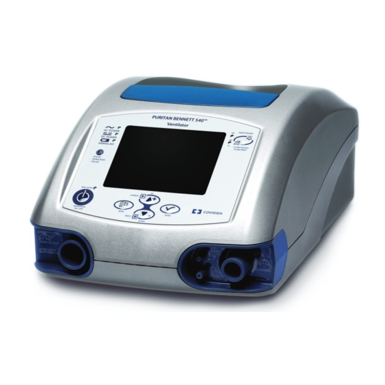
Page 122: Figure C-1. Puritan Bennett 540™ Portable Ventilator
Puritan Bennett. 5. Clean the ventilator with a mild soap solution, if necessary (refer to chapter “Cleaning”). 6. Ensure that the air inlet filter is installed. Figure C-1. Puritan Bennett 540™ Portable Ventilator Puritan Bennett 540™ Ventilator User’s Manual... - Page 123 Figure C-2. Dual Bag Puritan Bennett 540™ Ventilator User’s Manual...
- Page 124 Unpacking and Preparation This page intentionally blank Puritan Bennett 540™ Ventilator User’s Manual...
-
Page 125: D Modes And Breath Types
D Modes and Breath Types Modes of Ventilation This chapter is a general description of the various modes of ventilation and breath types available with the Puritan Bennett 540™ Ventilator. Note: The default ventilation mode setting is PRES A/C; for more information, see below. -
Page 126: Psv/Cpap Mode
(Pressure Support) to each of the patient’s breaths. This has the same benefits as CPAP, with the additional benefit of assisting the patient in moving air into his or her lungs. Puritan Bennett 540™ Ventilator User’s Manual... -
Page 127: E Parts And Accessories
E Parts and Accessories Table E-1 provides a list of accessories that are available for the Puritan Bennett 540™ Ventilator. To order parts or accessories, contact your equipment supplier or Puritan Bennett representative. Note: The ventilator is shipped from the factory with the following items: a printed User’s Manual; a CD with Clinician’s Manual (printed copy available upon request);... - Page 128 Allegiance™/Cardinal™/Airlife™ single limb patient circuit, 6463-H08 ADULT Hudson™, Allegiance™, Cardinal™, and Airlife™ are the property of their respective owners. For more information regarding parts and accessories for the Puritan Bennett 540™ Ventilator contact your service representative or www.puritanbennett.com. Puritan Bennett 540™ Ventilator User’s Manual...
-
Page 129: F Glossary
“Alarm Silence. ” Back Up Rate Rate of control cycles in PSV or SIMV modes during apnea phase. Battery Level Display of the remaining battery capacity; located adjacent to the battery symbol. Puritan Bennett 540™ Ventilator User’s Manual... - Page 130 Exhalation sensitivity The exhalation sensitivity (Exh Sens) level is a percentage of peak flow at which a pressure-supported breath will be terminated. Expiratory Tidal Volume (VTI) Volume exhaled by the patient at each expiratory phase. Puritan Bennett 540™ Ventilator User’s Manual...
- Page 131 Counter for the total ventilation time since manufacture or the last CPU board change. Mains AC power supply. Mean Airway Pressure. Average pressure during a ventilation cycle. Minimum Exhalation Time Minimum exhalation time before allowing the patient inspiratory trigger. Puritan Bennett 540™ Ventilator User’s Manual...
- Page 132 Pressure is maintained until inspiratory flow is reduced to a percentage of peak flow that depends on the expiratory sensitivity setting for the inspiration, when the ventilator cycles into exhalation. Available in SIMV or Spontaneous modes. Pounds Per Square Inch. Rebreathing The patient breathes his/her exhaled gas. Puritan Bennett 540™ Ventilator User’s Manual...
- Page 133 The Puritan Bennett 540™ Ventilator is flow-triggered, with sensitivity levels in the range from 1 to 5: the lower the number, the more sensitive the trigger.
- Page 134 Glossary This page intentionally blank Puritan Bennett 540™ Ventilator User’s Manual...
-
Page 135: Index
CAL FAULT 3-16 silencing CALIBRATION FAIL 3-14 3-8, 3-16 Troubleshooting CHECK PROXIMAL LINE1 Alarms and troubleshooting CHECK PROXIMAL LINE2 3-8, 3-16 Alarms, utilization CHECK SETTINGS 3-8, 3-9, 3-16 Alarms, ventilation CHECK/CHANGE EXH VALVE1 Index-1 Puritan Bennett 540™ Ventilator User’s Manual... - Page 136 CHK EXH VALV RESTART VENT alarm message EMPTY BATTERY alarm message 3-16 Environment 3-9, CHK VOL/INSP TIME SETTINGS alarm message suitable for use of ventilator 3-17 A-12 Environmental specifications 4-12 Classification of device Exhalation block Cleaning replacement interval Index-2 Puritan Bennett 540™ Ventilator User’s Manual...
- Page 137 OCCLUSION CHECK CIRCUIT alarm message 3-20 testing 3-12, 3-20, Internal battery, replacing (figure) ON INTERNAL BATTERY alarm message 3-11, 3-19 INVERSED IE RATIO alarm message I/O switch (figure) Operational verification checklist Operator/Users Index-3 Puritan Bennett 540™ Ventilator User’s Manual...
- Page 138 Standards, compliance, and IEC clasiification specifica- A-17 installation tions environment Starting ventilation maintenance Stopping ventilation 1-10 oxygen Storing the internal battery 4-14 Precautions for use, warnings Stud, oxygen connector general Index-4 Puritan Bennett 540™ Ventilator User’s Manual...
- Page 139 Turning on unpacking and preparation 1-3, 7-1 Ventilator, and liquid ingress (Warning) Warnings definition of general list of Preface-1 Warranty Waveforms menu Welcome Menu screen display of skipping Index-5 Puritan Bennett 540™ Ventilator User’s Manual...
- Page 141 Nellcor Puritan Bennett LLC 6135 Gunbarrel Avenue, Boulder, CO 80301 U.S.A. Telephone Toll Free 1.800.255.6774 © 2009 Nellcor Puritan Bennett LLC. All rights reserved. 10028295Rev B-0109...
Need help?
Do you have a question about the Puritan Bennett 540 and is the answer not in the manual?
Questions and answers