Table of Contents
Advertisement
Quick Links
Industrial Automation Headquarters
Delta Electronics, Inc.
Taoyuan Technology Center
No.18, Xinglong Rd., Taoyuan City,
Taoyuan County 33068, Taiwan
TEL: 886-3-362-6301 / FAX: 886-3-371-6301
Asia
Delta Electronics (Jiangsu) Ltd.
Wujiang Plant 3
1688 Jiangxing East Road,
Wujiang Economic Development Zone
Wujiang City, Jiang Su Province,
People's Republic of China (Post code: 215200)
TEL: 86-512-6340-3008 / FAX: 86-769-6340-7290
Delta Greentech (China) Co., Ltd.
238 Min-Xia Road, Pudong District,
ShangHai, P.R.C.
Post code : 201209
TEL: 86-21-58635678 / FAX: 86-21-58630003
Delta Electronics (Japan), Inc.
Tokyo Office
2-1-14 Minato-ku Shibadaimon,
Tokyo 105-0012, Japan
TEL: 81-3-5733-1111 / FAX: 81-3-5733-1211
Delta Electronics (Korea), Inc.
1511, Byucksan Digital Valley 6-cha, Gasan-dong,
Geumcheon-gu, Seoul, Korea, 153-704
TEL: 82-2-515-5303 / FAX: 82-2-515-5302
Delta Electronics Int'l (S) Pte Ltd
4 Kaki Bukit Ave 1, #05-05, Singapore 417939
TEL: 65-6747-5155 / FAX: 65-6744-9228
Delta Electronics (India) Pvt. Ltd.
Plot No 43 Sector 35, HSIIDC
Gurgaon, PIN 122001, Haryana, India
TEL : 91-124-4874900 / FAX : 91-124-4874945
Americas
Delta Products Corporation (USA)
Raleigh Office
P.O. Box 12173,5101 Davis Drive,
Research Triangle Park, NC 27709, U.S.A.
TEL: 1-919-767-3800 / FAX: 1-919-767-8080
Delta Greentech (Brasil) S.A
Sao Paulo Office
Rua Itapeva, 26 - 3° andar Edificio Itapeva One-Bela Vista
01332-000-São Paulo-SP-Brazil
TEL: +55 11 3568-3855 / FAX: +55 11 3568-3865
Europe
Delta Electronics (Netherlands) B.V.
Eindhoven Office
De Witbogt 20, 5652 AG Eindhoven, The Netherlands
TEL: +31 (0)40-8003800 / FAX: +31 (0)40-8003898
*We reserve the right to change the information in this catalogue without prior notice.
DELTA_IA-MDS_VFD-HES_UM_EN_20190222
Delta Hybrid Energy Saving
System
HES Series User Manual
www.deltaww.com
Advertisement
Table of Contents

Subscribe to Our Youtube Channel
Related Manuals for Delta HES Series


Summary of Contents for Delta HES Series
- Page 1 1511, Byucksan Digital Valley 6-cha, Gasan-dong, Geumcheon-gu, Seoul, Korea, 153-704 Delta Hybrid Energy Saving TEL: 82-2-515-5303 / FAX: 82-2-515-5302 Delta Electronics Int’l (S) Pte Ltd System 4 Kaki Bukit Ave 1, #05-05, Singapore 417939 TEL: 65-6747-5155 / FAX: 65-6744-9228 HES Series User Manual Delta Electronics (India) Pvt.
- Page 2 All information contained in this user manual is the exclusive property of Delta Electronics Inc. (hereinafter referred to as "Delta ") and is protected by copyright law and all other laws. Delta retains the exclusive rights of this user manual in accordance with the copyright law and all other laws. No parts in this manual may be reproduced, transmitted, transcribed, translated or used in any other ways without the prior consent of Delta.
- Page 3 Please carefully read the contents of the instructions that are marked with "Danger" and "caution". Please contact your local Delta agents for any questions and our professional team will be happy to assist you. PLEASE READ PRIOR TO INSTALLATION FOR SAFETY.
- Page 4 When Hybrid Servo Controller uses external terminals as its run command sources, the servo oil pump may start running immediately after the power is connected, which may be dangerous with any personnel present. Please choose a safe area to install Hybrid Energy System, where there is no high temperature, direct sunlight, moisture, and water dripping and splash.
-
Page 5: Table Of Contents
Table of Contents Chapter 1 Use and Installation 1-1 Exterior of Product ............................ 1-2 1-2 Specifications ............................1-3 1-3 Introduction of Hybrid Energy System ...................... 1-8 1-4 Installation ..............................1-9 Chapter 2 Wiring 2-1 Wiring ............................... 2-2 2-2 Wiring of Servo oil Pump .......................... 2-9 2-3 Main Circuit ............................. - Page 6 Chapter 6 Maintenance 6-1 Maintenance and Inspection ........................6-2 6-2 Greasy Dirt Problem ..........................6-2 6-1 Fiber Dust Problem ..........................6-2 6-1 Erosion Problem ............................6-2 6-1 Industriasl Dust Problem .......................... 6-2 6-1 Wiring and Installation Problem ....................... 6-2 6-1 Multi-funciton Input/ Output Terminals Problem ..................6-2 Appendix A.
-
Page 7: Chapter 1 Use And Installation
Chapter 1 Use and InstallationHES Series Chapter 1 Use and Installation 1-1 Exterior of Product 1-2 Product Specifications 1-3 Introduction of Hybrid Energy System 1-4 Product Installation Upon receipt of the product, the clients are advised to keep the product in its original packaging box. -
Page 8: Exterior Of Product
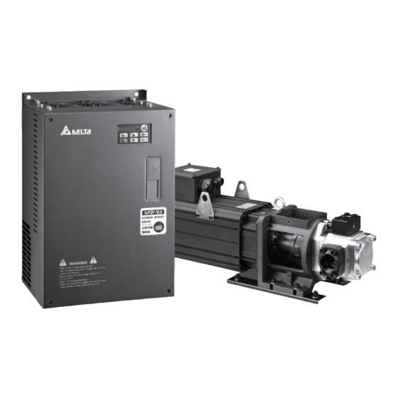
Chapter 1 Use and InstallationHES Series 1-1 Exterior of Product All Hybrid Energy System has passed strict quality control before being shipped out from the factory, with enforced packaging that sustains impacts. Upon opening the packaging of the Hybrid Energy System, the customers are recommended to conduct the examination by the following steps: ... -
Page 9: Specifications
Chapter 1 Use and InstallationHES Series 1-2 Specifications 230V Series Specifications HES____23A HES____23A Model Name 063H 080G 080H 100G 100H 100Z 125G 125H 160G 160H 200G Oil Pump Capacity cc/rev Flow Rate L/min Linearity Below 1% F.S. Magnetic Hysteresis Below 1% F.S. - Page 10 Chapter 1 Use and InstallationHES Series 230V Series HES____23C HES____23C Model Name 063H 080H 100H 125H 160H 200H 250G Oil Pump Capacity cc/rev Flow Rate L/min Flow rate Linearity Below 1% F.S. Specifications Magnetic Below 1% F.S. Hysteresis Maximum Pressure...
- Page 11 Chapter 1 Use and InstallationHES Series 460V Series Specifications HES____43A HES____43A Model Name 063G 063H 080G 080H 100G 100H 100Z 125G 125H 160G 160H 200G Oil Pump Capacity cc/rev Flow Rate L/min Linearity Below 1% F.S. Magnetic Below 1% F.S.
- Page 12 Chapter 1 Use and InstallationHES Series 460V Series Specifications HES____43C HES___43C Model Name 063H 080H 100H 125H 160H 200H 250M 320M Oil Pump Capacity cc/rev Flow Rate L/min Linearity Below 1% F.S. Magnetic Below 1% F.S. Hysteresis Maximum Pressure Minimum...
- Page 13 Chapter 1 Use and InstallationHES Series 460V Series HES____43C HES___43C Model Name 063M 080M 100M 125M 160M 200M Oil Pump Capacity cc/rev Flow Rate L/min Linearity Below 1% F.S. Magnetic Below 1% F.S. Hysteresis Maximum Pressure Minimum Pressure Linearity Below 1% F.S.
-
Page 14: Introduction Of Hybrid Energy System
Chapter 1 Use and InstallationHES Series 1-3 Introduction of Hybrid Energy System Pressure Command Delta Hybrid (0~10V) Injector Servo Pressure Controller Controller Sensor Flow Rate Command (0~10V) PG Card U V W Over heat protection Power Terminal Brake resistance/ Brake Unit... -
Page 15: Installation
Chapter 1 Use and InstallationHES Series 1-4 Installation Servo Oil Pump Install the servo oil pump in an environment with the following conditions to ensure safe product operation: Conditions of Operation Ambient Temperature 0°C~ 40°C Environment Relative Humidity 20%~90%, No condensation Oil Temperature 0°C~ 60°C (15°C~ 50°C is recommended) - Page 16 Chapter 1 Use and InstallationHES Series HES version C: The figure below shows that HES version C is installed on the machine. Beside absorbing the vibration produced by the running motor, the height and the position of the anti-vibration rubber pads can also be adjusted.
- Page 17 Chapter 1 Use and InstallationHES Series Pipelines & Connections Remove all protection caps on the pump Choose suitable oil tube and connectors (Maximum intake flow rate 1m/s) Recommended Specifications of intake oil tube Flow Rate(L/min) Tube Diameter (inch) Length (m) Above 1.5...
- Page 18 Chapter 1 Use and InstallationHES Series Installation Space Air Flow mm (inch) mm (inch) 7.5-20HP 75 (3) 175 (7) 25-75HP 75 (3) 200 (8) 100HP 75 (3) 250 (10) The Hybrid Servo Controller must be installed vertically with screws to sturdy structures. Do not install it upside down, tilted, or horizontally.
-
Page 19: Chapter 2 Wiring
Chapter 2 WiringHES Series Chapter 2 Wiring 2-1 Wiring 2-2 Wiring of Servo Oil Pump 2-3 Descriptions of Main circuit Terminals 2-4 Descriptions of Control Loop Terminals Upon opening the top cover of the Hybrid Servo Controller and reveal the wiring terminal bus, check if the terminals of each Main circuit and control loop circuit are labeled clearly. - Page 20 Chapter 2 WiringHES Series 2-1 Wiring The wiring of the hybrid energy system consists of that for the servo oil pump and that for the Hybrid Servo Controller. The user must follow the wiring loop below for all wire connections.
- Page 21 Chapter 2 WiringHES Series HES125H23A~HES200G23A; HES160H43A~HES200G43A; Bra ke Bra ke U n it R e sisto r VFD B C o n tro lle r No te 1 * Ou tp u t Te rmin a l 220V No te 2 *...
- Page 22 Chapter 2 WiringHES Series HES063H23C, HES080H23C, HES100H23C, HES125H23C, HES063H43C, HES080H43C, HES100H43C, HES125H43C, HES160H43C, HES200H43C, HES063M43C, HES080M43C, HES100M43C, HES125M43C, HES160M43C, HES200M43C Brake Resistor Controller +2/B1 Output Terminals 220V Note 2* Unused Start Input Terminals Oil Pump R ES Reset Unused C OM...
- Page 23 Chapter 2 WiringHES Series HES160H23C, HES200H23C, HES250G23C, HES250M43C, HES320M43C Bra ke U n it Bra ke VFD B R e sisto r C o n tro lle r No te 1 * Output Terminals 2 2 0 V No te 2 *...
- Page 24 Chapter 2 WiringHES Series Note 1* The RA, RC wiring of the braking unit: the overheat protection wiring of the braking unit. Note 2* For models with power rating below 22kW / 460V For models with power rating above 22kW/460V (including 22kW).
- Page 25 Chapter 2 WiringHES Series Multi-pump Operation Mode Confluence Mode Ma s te r 1 S la ve (0 3-1 3 =1 ) (0 3-1 3 =2 o r 3 ) Pressure Pressure Feedback Command Combine Command Hydraulic Pump Activation S ON...
- Page 26 Chapter 2 WiringHES Series When the signals are Confluence, the communication will be a short circuit. When the signals are Diversion, the communication becomes an open circuit. Pressure SG+ SG- SG+ SG- SG+ SG- SG+ SG- Command Pressure Command Flow Command...
-
Page 27: Wiring Of Servo Oil Pump
Chapter 2 WiringHES Series 2-2 Wiring of Servo Oil Pump HES_____A servo oil pump: Electric Box Delta Hydraulic Servo Motor Corresponding to Controller PG Card Hydraulic Servo Motor Controller U V W (Crimp Terminal Temperature Rise Specification as Protection Switch... - Page 28 Chapter 2 WiringHES Series Encoder CBHE-E5M: PTC (ye llo w) KTY- (b la ck/ wh ite ) KTY+ (re d / w h ite ) PTC (ye llo w / b la ck) (tin co a te d ) PTC (ye llo w ) The colors mentioned in the Connector Pin Definition table are only the colors of lines inside the motor.
- Page 29 Chapter 2 WiringHES Series Crimp Terminals Terminal Torque: 82kg-m (71in-lbf) Figure 1 Figure 2 External Wiring of Hybrid Servo Controller Power Supply Power Please follow the power rating listed in the Supply user's manual (chapter 1) A larger current may be generated when the...
-
Page 30: Main Circuit
Chapter 2 WiringHES Series 2-3 Main Circuit Terminal Label Description R/L1, S/L2, T/L3 AC line input terminals U/T1, V/T2, W/T3 Output of Hybrid Servo Controller, connected to hybrid servo motor For power improvement of the connection terminal of DC reactor. Please... - Page 31 Chapter 2 WiringHES Series To avoid lightning strike and incidence of electrocution, the external metal ground wire for the electrical equipments must be thick and short and connected to the ground terminal of the Hybrid Servo Controller system. ...
- Page 32 Chapter 2 WiringHES Series Please use isolation wire or wire tube for power supply wiring and ground the isolation layer or both ends of wire tube. Output terminals for main circuit (U, V, W) : The output side of Hybrid Servo Controller cannot be connected with advance phase capacitor, surge absorber, advance phase capacitor, or L-C and R-C filters.
- Page 33 Chapter 2 WiringHES Series Main Circuit Terminals tightening torque Model No. Wiring on the drive's Crimp Terminal terminal HES063H23A Ring lug Ring lug HES063H23C 4AWG 30kgf-cm (21mm (26 lbf-in) Heat Shrink Tube HES080G23A WIRE HES080H23A 4AWG (21mm HES080H23C 4AWG HES100G23A...
- Page 34 HES160H23A, HES200G23A installations must use 90ºC wires. The other model use UL installations must use 600V, 75ºC or 90ºC wire. Use copper wire only. Contact Delta for more information; if you want to use higher class of overheat protection material. 2-16...
-
Page 35: Controlterminals
Chapter 2 WiringHES Series 2-4 Control Terminals Description of SINK(NPN)/SOURCE(PNP)Mode Switching Terminal Sink m ode Source mode With internal power (+24Vdc) With internal p ower (+24Vdc) SO N SO N R ES R ES +2 4 V +2 4 V... - Page 36 Chapter 2 WiringHES Series Frame Torque Wire Gauge C, D, E 8 kgf-com (6.9 in-lbf) 22-14 AWG (0.3-2.1mm Terminal: 0V/24V 1.6 kgf-com(1.4 in-lbf) 30-16 AWG (0.051-1.3mm Factory Setting (NPN mode) Terminal Function Between terminals SON-DCM: conducting (ON) ; run: open...
- Page 37 Chapter 2 WiringHES Series Factory Setting (NPN mode) Terminal Function Flow Rate Command Impedance:200kΩ Resolution:12 bits Range:0 ~ 10V=0~maxium flow rate Power supply for analog configuration +10V 20mA (variable +10V Configuration Voltage resistor 3~5kΩ) Power supply terminal of pressure Configuration power supply for pressure sensor +24V...
- Page 38 Chapter 2 WiringHES Series Threaded for three rounds or more in the sam e phase Output term inal Ferrite core Transistor outputs (MO1, MO2, MCM) Make sure to connect the digital outputs to the right polarity. When connecting a relay to the digital outputs connect a surge absorber across the coil and check the polarity.
-
Page 39: Chapter 3 Start Up
Chapter 3 Flow of machine AdjustmentHES Series Chapter 3 Start Up 3-1 Description of Control Panel 3-2 Adjustment Flow Chart 3-3 Explanations for the Adjustment Steps Please verify again before operation that the wiring is done correctly, especially that the output terminals U/T1, V/T2, and W/T3 of the Hybrid Servo Controller cannot have any power input. -
Page 40: Description Of Control Panel
Chapter 3 Flow of machine AdjustmentHES Series 3-1 Description of Control Panel Description of the Digital Keypad KPVJ-LE01 Run key start AC drive operation Stop/Reset key Stop driver operation and reset in case of anomaly Status Display Display the driver’s current status. - Page 41 Chapter 3 Flow of machine AdjustmentHES Series Display Message Descriptions External Fault. Display “End” for approximately 1 second if input has been accepted by pressing key. After a parameter value has been set, the new value is automatically stored in memory. To modify an entry, use the keys.
- Page 42 Chapter 3 Flow of machine AdjustmentHES Series Reference Table for the 7-segment LED Display of the Digital Keypad Numeric Seven-segment Display English Letter Seven-segment - - - - Display English Letter Seven-segment - - - Display English Letter Seven-segment -...
-
Page 43: Adjustment Flow Chart
Chapter 3 Flow of machine AdjustmentHES Series 3-2 Adjustment Flow Chart Set the Hybrid servo motor code Check if the pressure Troubleshoot feedback signal is normal Y E S Calibrate pressure and flow commands Execute venting Adjust Injection /Hold up Complete *The firmware version is 2.04 and above, just proceed the process to set up HES ID code. -
Page 44: Explanations For The Adjustment Steps
Chapter 3 Flow of machine AdjustmentHES Series 3-3 Explanations for the Adjustment Steps Operate the following steps with the digital operator (KPVJ-LE01/ KPV-CE01) Prior to starting running, please verify again if the wiring is correct, especially that the output terminals U/T1, V/T2, and W/T3 of the Hybrid Servo Controller must correspond to the U, V, and W terminals of the Hybrid servo motor, respectively. - Page 45 Chapter 3 Flow of machine AdjustmentHES Series 245 MSJ-IR202HE42 27kW, 380V motor For firmware version 2.04 and above Step 2. Entry HES ID code* Do not connect the external terminals SON-COM and EMG-COM for the time being. Restore the factory default values by setting the Parameter 00-02 = 10 ...
- Page 46 Chapter 3 Flow of machine AdjustmentHES Series Verify if the setting value of Pr01-18 (Rated power of the synchronous motor) is the rated power (kW) of the corresponding motor. Verify also if the setting value of Pr00-07(Maximum value for the pressure command (bar)) fits version G, H, Z, and M.
- Page 47 Chapter 3 Flow of machine AdjustmentHES Series With the maximum pressure set by the controller, observe the associated value displayed on the operation panel and set it to 00-14. With the controller setting at half the maximum pressure, observe the associated value ...
- Page 48 Chapter 3 Flow of machine AdjustmentHES Series In case of power outage, connect SON-COM and turn on the power supply. Step 6. Bleed the circuit and make sure if there is any plastic material in the barrel. The machine can start operation only when there are no plastic materials inside the barrel.
- Page 49 Chapter 3 Flow of machine AdjustmentHES Series Troubleshooting for Pressure Instability Unstable pressure over the entire section Set Pr. 00-09 = 0 for speed control With the oil line in the closed state, send the low speed rotation command to make the pressure feedback 40~50% of the pressure command value (Pr.
- Page 50 Chapter 3 Flow of machine AdjustmentHES Series Confluence Machine Tuning Procedure Follow the associated descriptions in Chapter 2 to lay out the wiring. Follow steps 1 and 2 described above to enter the electrical codes for the master/slave machines. Then proceed with the steps below.
- Page 51 Chapter 3 Flow of machine AdjustmentHES Series For firmware version 2.03 and above, set the Parameter 01-01=2 Source of operation command Setting value 0: Operation by using the digital keypad of Pr. 01-01 1: Operation by using the external terminals. The Stop button on the keypad is disabled.
- Page 52 Chapter 3 Flow of machine AdjustmentHES Series Shut off the power and the re-supply power for the Slave, and then set the Slave in the speed control mode Speed Control Mode Setting value 0: Speed control of Pr. 00-09 1: Pressure control In this case, the Master can be tuned according to the Step 3 –...
-
Page 53: Chapter 4 Parameter Functions
HES Series Chapter 4 Parameter Functions Chapter 4 Parameters 4-1 Summary of Parameter Settings 4-2 Detailed Description of Parameters... -
Page 54: Summary Of Parameter Settings
HES Series Chapter 4 Parameter Functions 4-1 Summary of Parameter Settings 00 System Parameters You can set this parameter during operation Parameter Default Function of the parameter Settings code value 12:230V, 7.5HP 13:460 V, 7.5HP 14:230V, 10HP 15:460V, 10HP 16:230V, 15HP... - Page 55 HES Series Chapter 4 Parameter Functions Parameter Default Function of the parameter Settings code value 0: Display the output current (A) 1: Reserved 2: Display the actual output frequency (H) 3: Display the DC-BUS voltage (U) 4: Display the output voltage (E)
- Page 56 HES Series Chapter 4 Parameter Functions Parameter Default Function of the parameter Settings code value Flow command filtering time 00-13 0.000 ○ ○ ○ 0.000~1.000 second Percentage of the pressure 00-14 56.0 ○ ○ ○ 0.0~100.0% command value (Max) Percentage of the pressure ...
- Page 57 HES Series Chapter 4 Parameter Functions Parameter Default Function of the parameter Settings code value 00-49 Flow reference S2 time 0~1000ms ○ ○ ○ 00-50 Speed bandwidth 2 0~40Hz ○ ○ ○ 00-51 Speed bandwidth 3 0~40Hz ○...
- Page 58 HES Series Chapter 4 Parameter Functions 01 Motor Parameters You can set this parameter during operation. Parameter Default Function of the parameter Settings code value 0: VF 1: Reserved 2: Reserved 01-00 ○ ○ ○ Control mode 3: FOCPG...
- Page 59 (Lq) of the synchronous 0.00.0~655.35mH ○ motor Back EMF of the 01-25 ○ 0~65535 V/ krpm synchronous motor 0: ABZ 1: ABZ+HALL (only used for Delta’s servo motors) 01-26 ○ Encode type 2: ABZ+HALL 3: Resolver PG Offset angle of 01-27 0.0~360.0° ○...
- Page 60 HES Series Chapter 4 Parameter Functions Parameter Default Function of the parameter Settings code value ○ ○ ○ Flux-Weakening voltage 01-38 0~100V level...
- Page 61 HES Series Chapter 4 Parameter Functions 02 Parameters for Protection You can set this parameter during operation. Parameter Function of the Default Settings code parameter value 230V series: 350.0~450.0V 380.0 02-00 ○ ○ Software brake level ○ 760.0 460V series: 700.0~900.0V...
- Page 62 HES Series Chapter 4 Parameter Functions Parameter Function of the Default Settings code parameter value ○ ○ 45: PG slip error (PGF4) 46: Reserved ○ ○ ○ ○ ○ ○ 47: Reserved 48: Reserved ○ ○ ○ 49: External fault input (EF) 50: Emergency stop (EF1) ○...
- Page 63 HES Series Chapter 4 Parameter Functions 03 Digital/Analog Input/Output Parameters You can set this parameter during operation. Parameter Default Function of the parameter Settings code value Multi-function input 0: No function 03-00 ○ ○ ○ command 3 (MI3) 44: Injection signal input...
- Page 64 HES Series Chapter 4 Parameter Functions 4-2 Description of Parameter Settings 00 System Parameters You can set this parameter during operation Hybrid Servo Controller model code ID FOCPG FOCPM Control mode Factory default: Read only Settings Read only Display of rated current of the Hybrid Servo Controller...
- Page 65 HES Series Chapter 4 Parameter Functions 7: Display the actual motor speed(r 00: forward speed; - 00: negative speed) 8: Display the estimated output torque (%) (t 0.0: positive torque; - 0.0: negative torque) (%) 9: Display the PG feedback (G)
- Page 66 HES Series Chapter 4 Parameter Functions Power factor -1.000~1.000=100% Power Rated power of the drive =100% Output torque Rated torque =100% (0~10V=0~100%) (0~10V=0~100%) (-10~10V=0~100%) 12~20 Reserved Display the speed (rpm) defined by the user Control mode FOCPG FOCPM Factory default: 0...
- Page 67 HES Series Chapter 4 Parameter Functions Speed bandwidth Control mode FOCPG FOCPM Factory default: 20 Settings 0~40Hz Set the speed response. The larger value indicates the faster response. Pressure feedback filtering time PO Pressure Command Filter Time PI ...
- Page 68 HES Series Chapter 4 Parameter Functions Example: If the pressure sensor indicates 250bar at 10V. If the controller’s maximum pressure of 140bar corresponds to 10V, then Parameter 00-07=140. Set the pressure as 140bar by using the controller, the voltage value shown on the display is about 56.0 (140/250 * 100%).
- Page 69 HES Series Chapter 4 Parameter Functions Pressure Pressure Feedback P3, I3 P2, I2 00-26 Pressure Command P2, I2 00-26 P1, I1 Time Adjust the Kp value to a proper level first, and then adjust the Ki value (time). If the pressure has overshoot, adjust the kd value.
- Page 70 HES Series Chapter 4 Parameter Functions Ramp up rate of pressure command Control mode FOCPG FOCPM Factory default: 0 Settings 0~1000ms Ramp down rate of pressure command FOCPG FOCPM Control mode Factory default: 100 Settings 0~1000ms Ramp the pressure value for the pressure command so as to reduce the vibration of the machine.
- Page 71 HES Series Chapter 4 Parameter Functions Reserved Overpressure detection level Control mode FOCPG FOCPM Factory default: 230 Settings 0~400 Bar When the pressure feedback exceeds this parameter setting, an “ovP over pressure” error message may occur. Firmware version 2.04 and above, maximum value 400Bar, the previous version’s maximum allowed value is 250Bar.
- Page 72 HES Series Chapter 4 Parameter Functions When Pr00-38=1 and Pr00-39=0, Pr00-42 is disable. Percentage of the maximum flow Control mode FOCPG FOCPM Factory default : 100 Settings 0~100% Set up this parameter to adjust the maximum rotation frequency (maximum flow rate). It is not necessary to stop the motor drive to set up this parameter.
- Page 73 HES Series Chapter 4 Parameter Functions Pressure Command Rising/ Descending S1 curve Control mode FOCPG FOCPM Factory default : 0 Settings 0~1000ms Pressure Command Rising/ Descending S2 Curve Control mode FOCPG FOCPM Factory default : 0 Settings 0~1000ms ...
- Page 74 HES Series Chapter 4 Parameter Functions Speed bandwidth 2 FOCPG FOCPM Factory default : 20 Control mode Settings 0~40Hz Speed bandwidth 3 FOCPG FOCPM Factory default : 20 Control mode Settings 0~40Hz To set up the response speed, the larger the value, the faster the reponse.
- Page 75 HES Series Chapter 4 Parameter Functions 01 Motor Parameters You can set this parameter during operation. Control mode Control mode FOCPG FOCPM Factory default: 5 0:V/F 1: Reserved 2: Reserved Settings 3: FOCPG 4: Reserved 5: FOCPM 6: Reserved This parameter determines the control mode of this AC motor.
- Page 76 HES Series Chapter 4 Parameter Functions (Pr01-19) and Number of poles of the synchronous motor (Pr.01-20) change. Motor’s rated voltage Control mode FOCPG Factory default: 220.0/440.0 Settings 230V series: 0.1~255.0V 460V series: 0.1~510.0V Typically, this setting is configured according to the rated operation voltage shown on the motor’s nameplate.
- Page 77 HES Series Chapter 4 Parameter Functions Set Pr01-07 as 1 and then press the RUN button on the keypad. The auto tuning process for the motor is carried out immediately. (Note: the motor starts running). After the process is finished, check if the motor’s parameters (Pr01-13 ~Pr01-16) have been automatically entered with the measurement data.
- Page 78 HES Series Chapter 4 Parameter Functions Rated current of the induction motor (A) Unit: Ampere FOCPG Control mode Factory default: #.## Settings 40~120% of the rated driving current To set this parameter, the user can set the rated motor current range shown on the motor’s nameplate.
- Page 79 Encoder type selection Control mode FOCPM Factory default: 3 Settings 0: ABZ 1: ABZ+HALL (only used for Delta’s servo motors) 2: ABZ+HALL 3: Resolver Look up table for Encoders & PG cards Parameter Setting Encoder Type Applicable PG Card...
- Page 80 HES Series Chapter 4 Parameter Functions PG Offset angle of synchronous motor Control mode FOCPM Factory default: 0.0 Settings 0.0~360.0° Offset angle of the PG origin for the synchronous motor. Number of poles of the resolver Control mode FOCPM...
- Page 81 HES Series Chapter 4 Parameter Functions Unity value of the system inertia Control mode FOCPG FOCPM Factory default: 260 Settings 1~65535 (256 = 1 per unit) Carrier frequency FOCPG FOCPM Control mode Factory default: 5 Settings 5 kHz; 10kHz ...
- Page 82 HES Series Chapter 4 Parameter Functions Change the rotation direction Control mode FOCPG FOCPM Factory default: 0 0: When the driver runs forward, the motor rotates counterclockwise. Settings When the driver runs reverse, the motor rotates clockwise. 1: When the driver runs forward, the motor rotates clockwise. When the driver runs reverse, the motor rotates counterclockwise.
- Page 83 HES Series Chapter 4 Parameter Functions Flux-Weakening Voltage Level Control mode FOCPG FOCPM Factory default: 10V Settings 0 ~100V The function of Pr01-38 is to adjust the flux-weakening voltage level. Adjust this parameter to use the voltage to lower the motor’s current when necessary. If you make the current too low, there’s a current distortion.
- Page 84 HES Series Chapter 4 Parameter Functions 02 Parameters for Protection You can set this parameter during operation. Software brake level Factory default: 380.0/760.0 Control mode FOCPG FOCPM Settings 230V series: 350.0~450.0Vdc 460V series: 700.0~900.0Vdc Sets the reference point of software brake. The reference value is the DC bus voltage.
- Page 85 HES Series Chapter 4 Parameter Functions 41: Reserved ○ ○ ○ 42: PG feedback error (PGF1) ○ ○ 43: PG feedback loss (PGF2) ○ ○ 44: PG feedback stall (PGF3) ○ ○ 45: PG feedback slip (PGF4) ○ ○ 46: Reserved ○...
- Page 86 HES Series Chapter 4 Parameter Functions This parameter defines the maximum value of the analog input for 100% of the activation level of the PTC. PTC detection filtering time Control mode FOCPG FOCPM Factory default: 0.20 Settings 0.00 – 10.00 seconds ...
- Page 87 HES Series Chapter 4 Parameter Functions Output frequency at malfunction Control mode Factory default: Read only FOCPG FOCPM Settings 0.00~655.35Hz Output voltage at malfunction Control mode Factory default: Read only FOCPG FOCPM Settings 0.0~6553.5V DC side voltage at malfunction Control mode...
- Page 88 HES Series Chapter 4 Parameter Functions Decode temporarily or cancel the password then you will be able to use keypad to copy parameters. But the password set at Pr02-22 will not be copied. When the parameters saved in the keypad are transferred to the hybrid servo drive, you will need to set up a password at Pr02-22 to enable parameter protection.
- Page 89 HES Series Chapter 4 Parameter Functions 03 Digital/Analog Input/Output Parameters You can set this parameter during operation. Multi-function input command 3 (MI3) Multi-function input command 4 (MI4) Multi-function input command 5 (MI5) Control mode FOCPG FOCPM Factory default: 0...
- Page 90 HES Series Chapter 4 Parameter Functions Multi-function output direction Control mode FOCPG FOCPM Factory default: 0 Settings 0~65535 This parameter is used for bit-wise setting. If the corresponding bit is 1, the multi-function output is set as reverse direction.
- Page 91 HES Series Chapter 4 Parameter Functions Confluence Master/Slave Selection Control mode FOCPG FOCPM Factory default: 0 Settings 0: No function 1: Master 1 2: Slave/Master 2 3: Slave/Master 3 In a stand-alone system, this parameter is set as 0 ...
- Page 92 HES Series Chapter 4 Parameter Functions Communication error treatment Control mode FOCPG FOCPM Factory default: 0 Settings 0: Warn and keep operation 1: Warn and ramp to stop 2: Warn and coast to stop 3: No action and no display ...
-
Page 93: Chapter 5 Methods Of Anomaly Diagnosis
HES Series Chapter 5 Methods of Anomaly Diagnosis Chapter 5 Methods of Anomaly Diagnosis 5-1 Unusual Signal 5-1-1 Indicator Display 5-1-2 Error Messages Displayed on Digital Operation Panel KPVJ-LE01 5-2 Over current (OC) 5-3 Ground fault (GFF) 5-4 Over voltage (OV) -
Page 94: Unusual Signal
HES Series Chapter 5 Methods of Anomaly Diagnosis 5-1 Unusual Signal 5-1-1 Indicator Display In d ica to r o f P G c a rd p o we r P o we r in d ic a to r... - Page 95 HES Series Chapter 5 Methods of Anomaly Diagnosis 5-1-2 Error Messages Displayed on Digital Operation Panel KPVJ-LE01 Display Code Description of Anomaly Troubleshooting 1. Check if the insulation of the wire from Over current occurs in U-V-W to the hybrid servo motor is bad.
- Page 96 HES Series Chapter 5 Methods of Anomaly Diagnosis Display Code Description of Anomaly Troubleshooting 2. For Hybrid Servo Controller with power below 22kW, the issue can be resolved by adjusting the software brake action level in Pr.02-00. 3. For Hybrid Servo Controller with power...
- Page 97 HES Series Chapter 5 Methods of Anomaly Diagnosis Display Code Description of Anomaly Troubleshooting 1. Check if ambient temperature is too high. Overheating of heat sink detected 2. Check if there is any foreign object on the by Hybrid Servo Controller, heat sink and if the fan is running.
- Page 98 HES Series Chapter 5 Methods of Anomaly Diagnosis Display Code Description of Anomaly Troubleshooting 1. Check if the transistor module fuse is bad. DC Fuse blown on (FUSE), for models below (including) 30HP 2. Check if the load side is shorted.
- Page 99 HES Series Chapter 5 Methods of Anomaly Diagnosis Display Code Description of Anomaly Troubleshooting Abnormal in OH1 hardware wire Send back to manufacturer for repair. Abnormal in OH2 hardware wire Send back to manufacturer for repair. Clamp current detection error...
- Page 100 HES Series Chapter 5 Methods of Anomaly Diagnosis Display Code Description of Anomaly Troubleshooting 1. Check if the wiring of the motor is correct. Auto tuning error (AuE) 2. Check if the motor’s parameter settings are correct. 1. Check if there is any zero shift at the pressure sensor.
-
Page 101: Over Current (Oc)
HES Series Chapter 5 Methods of Anomaly Diagnosis 5-2 Over Current (OC) over current over current in Over current in while running at deceleration acceleration constant speed Remove short circuit Check for any shorts between Troubleshoot or ground fault motor connection terminals U,... -
Page 102: Over Voltage (Ov)
It's likely hybrid servo controller breaks down or If the voltage of DC BUS malfunctions due to noise. exceeds the protection value in Please contact Delta for action assistance. Adjust the brake level and make sure it is higher than the local voltage... -
Page 103: Low Voltage (Lv)
If Lv occurs when the circuit If the capacity of power supply breaker and electromagnetic transformer is appropriate contactor are ON It's likely hybrid servo controller breaks down or malfunctions due to noise. Please contact Delta for assistance. 5-11... -
Page 104: Overheat (Oh1)
Heat sink is overheated Temperature detection circuit on Is the temperature of heat sink circuit board malfunctions. higher than 90 ˚ C Contact Delta for assistance. Reduce load Is load too heavy Is cooling fan running Replace cooling fan Remove the clog... -
Page 105: Phase Loss (Phl)
Tighten all screws plate tightened Please check wiring and Is voltage of the three phase power system for power supply unbalanced abnormal behavior It's likely hybrid servo controller breaks down or malfunctions due to noise. Please contact Delta for assistance. 5-13... - Page 106 HES Series Chapter 5 Methods of Anomaly Diagnosis 5-9 Electromagnetic/Induction Noise If there exist noise sources around Hybrid Servo Controller, they will affect Hybrid Servo Controller through radiation or the power lines, leading to malfunction of control loop and causing tripping or even damage of Hybrid Servo Controller.
-
Page 107: Environment And Facilities For Installation
HES Series Chapter 5 Methods of Anomaly Diagnosis 5-10 Environment and Facilities for Installation The Hybrid Servo Controller is a device for electronic components. Detailed descriptions of the environment suitable for its operation can be found in the specifications. If the listed regulations cannot be followed for any reason, there must be corresponding remedial measures or contingency solutions. -
Page 108: Chapter 6 Maintenance
Chapter 6 MaintenanceHES Series Chapter 6 Maintenance 6-1 Maintenance and Inspections 6-2 Greasy Dirt Problem 6-3 Fiber Dust Problem 6-4 Erosion Problem 6-5 Industrial Dust Problem 6-6 Wiring and Installation Problem 6-7 Multi-function Input/Output Terminals Problem The Hybrid Servo Controller has a comprehensive fault diagnostic system that includes several different alarms and fault messages. -
Page 109: Maintenance And Inspection
Chapter 6 MaintenanceHES Series 6-1 Maintenance and Inspections Before the check-up, always turn off the AC input power and remove the cover. Wait at least 10 minutes after all display lamps have gone out, and then confirm that the capacitors have fully discharged by measuring the voltage between DC+ and DC-. - Page 110 Chapter 6 MaintenanceHES Series Main circuit Maintenance Period Check Items Methods and Criterion Half Daily Year Year If there are any loose or missing screws Tighten or replace the screw ○ Visual inspection If machine or insulator is deformed, cracked,...
- Page 111 Chapter 6 MaintenanceHES Series Transformer and reactor of main circuit Maintenance Period Check Items Methods and Criterion Half Daily Year Year If there is any abnormal vibration or peculiar Visual, aural inspection and ○ smell smell Magnetic contactor and relay of main circuit...
- Page 112 Chapter 6 MaintenanceHES Series Ventilation channel of cooling system Maintenance Period Check Items Methods and Criterion Half Daily Year Year If there is any obstruction in the heat sink, air ○ Visual inspection intake or air outlet NOTE Please use the neutral cloth for clean and use dust cleaner to remove dust when necessary.
-
Page 113: Greasy Dirt Problem
Chapter 6 MaintenanceHES Series 6-2 Greasy Dirt Problem Serious greasy dirt problems generally occur in processing industries such as machine tools, punching machines and so on. Please be aware of the possible damages that greasy oil may cause to your drive: Electronic components that silt up with greasy oil may cause the drive to burn out or even explode. -
Page 114: Fiber Dust Problem
Chapter 6 MaintenanceHES Series 6-3 Fiber Dust Problem Serious fiber dust problems generally occur in the textile industry. Please be aware of the possible damages that fiber may cause to your drives: Fiber that accumulates or adheres to the fans will lead to poor ventilation and cause overheating problems. -
Page 115: Erosion Problem
Chapter 6 MaintenanceHES Series 6-4 Erosion Problem Erosion problems may occur if any fluids flow into the drives. Please be aware of the damages that erosion may cause to your drive. Erosion of internal components may cause the drive to malfunction and possibility to explode. -
Page 116: Industriasl Dust Problem
Chapter 6 MaintenanceHES Series 6-5 Industrial Dust Problem Serious industrial dust pollution frequently occurs in stone processing plants, flour mills, cement plants, and so on. Please be aware of the possible damage that industrial dust may cause to your drives: Dust accumulating on electronic components may cause overheating problem and shorten the service life of the drive. -
Page 117: Wiring And Installation Problem
Chapter 6 MaintenanceHES Series 6-6 Wiring and Installation Problem When wiring the drive, the most common problem is wrong wire installation or poor wiring. Please be aware of the possible damages that poor wiring may cause to your drives: Screws are not fully fastened. Occurrence of sparks as impedance increases. -
Page 118: Multi-Funciton Input/ Output Terminals Problem
Chapter 6 MaintenanceHES Series 6-7 Multi-function Input/Output Terminals Problem Multi-function input/output terminal errors are generally caused by over usage of terminals and not following specifications. Please be aware of the possible damages that errors on multi-function input/output terminals may cause to your drives: Input/output circuit may burns out when the terminal usage exceeds its limit. -
Page 119: Appendix A. Instructions Of Product Packaging
Appendix A. Instructions of Product PackagingHES Series Appendix A: Instructions of Product Packaging A-1 Descriptions of Product packaging: version A A-2 Unpacking: version A A-3 Detailed List of Product Packaging: version A A-4 Detailed List of Product Packaging: version C ... -
Page 120: Descriptions Of Product Packaging: V.a
Appendix A. Instructions of Product PackagingHES Series A-1 Descriptions of Product Packaging: v. A Packaging of the external box Models: Models: HES063H23A; HES080G23A; HES080H23A; HES125G23A; HES125G43A; HES100G23A; HES100H23A; HES063G43A;HES063H43A; HES080G43A; HES080H43A; HES100G43A; HES100H43A; Models: HES125H23A; HES160G23A; HES125H43A; HES160G43A; HES160H43A; HES200G43A... -
Page 121: Unpacking: V.a
Appendix A. Instructions of Product PackagingHES Series A-2 Unpacking: v. A STEP 1: Use flat head screwdriver to remove all the clips on the side of the crate. STEP 2: Remove the bubble bag and the tube. STEP 3: Lift the drive by using two lifting holes. -
Page 122: Detailed List Of Product Packaging: V.a
Appendix A. Instructions of Product PackagingHES Series A-3 Detailed List of Product Packaging: v.A HES063H23A 1 Servo controller VFD110VL23A06HA, corresponding PG card EMVJ-PG02R Unit: mm[inch] Frame 235.0 [9.25] 204.0 [8.03] 350.0 [13.78] 337.0 [13.27] 146.0 [5.75] 6.5 [0.26] 2 Servo oil pump HSP-025-110-23A... - Page 123 Appendix A. Instructions of Product PackagingHES Series 3 Accessory Kit HESP-063-H-N-23 Component Model Number Quantity ※ Braking resistor BR1K0W8P3 Coding device cable 5m Magnetic ring of power cable Sensor clamp ※ Braking resistor 1000W 8.3Ω Unit: min...
- Page 124 Appendix A. Instructions of Product PackagingHES Series HES080G23A 1 Servo controller VFD110VL23A08GA, corresponding PG card EMVJ-PG02R Unit: mm[inch] Frame 235.0 [9.25] 204.0 [8.03] 350.0 [13.78] 337.0 [13.27] 146.0 [5.75] 6.5 [0.26] 2 Servo oil pump HSP-032-110-23A Component Model Number Quantity...
- Page 125 Appendix A. Instructions of Product PackagingHES Series 3 Accessory Kit HESP-080-G-N-23 Component Model Number Quantity BR1K0W8P3 ※ Braking resistor Coding device cable 5m Magnetic ring of power cable Sensor clamp ※ Braking resistor 1000W 8.3Ω Unit: min...
- Page 126 Appendix A. Instructions of Product PackagingHES Series HES080H23A 1 Servo controller VFD150VL23A08HA, corresponding PG card EMVJ-PG02R Unit: mm[inch] Frame 255.0 [10.04] 226.0 [8.90] 403.8 [15.90] 384.0 [15.12] 168.0 [6.61] 8.5 [0.33] 2 Servo oil pump HSP-032-110-23A Component Model Number Quantity...
- Page 127 Appendix A. Instructions of Product PackagingHES Series 3 Accessory Kit HESP-080-H-N-23 Component Model Number Quantity BR1K0W5P8 ※ Braking resistor Coding device cable 5m Magnetic ring of power cable Sensor clamp ※ Braking resistor 1000W 5.8Ω Unit: min...
- Page 128 Appendix A. Instructions of Product PackagingHES Series HES100G23A 1 Servo controller VFD150VL23A10GA, corresponding PG card EMVJ-PG02R Unit: mm[inch] Frame 255.0 [10.04] 226.0 [8.90] 403.8 [15.90] 384.0 [15.12] 168.0 [6.61] 8.5 [0.33] 2 Servo oil pump HSP-040-110-23A Component Model Number Quantity...
- Page 129 Appendix A. Instructions of Product PackagingHES Series 3 Accessory Kit HESP-100-G-N-23 Component Model Number Quantity BR1K0W5P8 ※ Braking resistor Coding device cable 5m Magnetic ring of power cable Sensor clamp ※ Braking resistor 1000W 5.8Ω Unit: min A-11...
- Page 130 Appendix A. Instructions of Product PackagingHES Series HES100H23A 1 Servo controller VFD185VL23A10HA, corresponding PG card EMVJ-PG02R Unit: mm[inch] Frame 255.0 [10.04] 226.0 [8.90] 403.8 [15.90] 384.0 [15.12] 168.0 [6.61] 8.5 [0.33] 2 Servo oil pump HSP-040-110-23A Component Model Number Quantity...
- Page 131 Appendix A. Instructions of Product PackagingHES Series 3 Accessory Kit HESP-100-H-N-23 Component Model Number Quantity BR1K0W5P8 ※ Braking resistor Coding device cable 5m Magnetic ring of power cable Sensor clamp ※ Braking resistor 1000W 5.8Ω Unit: min A-13...
- Page 132 Appendix A. Instructions of Product PackagingHES Series HES100Z23A 1 Servo controller VFD220VL23A10ZA, corresponding PG card EMVJ-PG02R Unit: mm[inch] Frame 255.0 [10.04] 226.0 [8.90] 403.8 [15.90] 384.0 [15.12] 168.0 [6.61] 8.5 [0.33] 2 Servo oil pump HSP-040-150-23A 783.4 433.0 165.0 185.4 1"PT(¤...
- Page 133 Appendix A. Instructions of Product PackagingHES Series 3 Accessory Kit HESP-100-Z-N-23 Component Model Number Quantity BR1K0W5P8 ※ Braking resistor Coding device cable 5m Magnetic ring of power cable Sensor clamp ※ Braking resistor 1000W 5.8Ω Unit: min A-15...
- Page 134 Appendix A. Instructions of Product PackagingHES Series HES125G23A 1 Servo controller VFD220VL23A12GA, corresponding PG card EMVJ-PG02R Unit: mm[inch] Frame 255.0 [10.04] 226.0 [8.90] 403.8 [15.90] 384.0 [15.12] 168.0 [6.61] 8.5 [0.33] 2 Servo oil pump HSP-050-150-23A Component Model Number Quantity...
- Page 135 Appendix A. Instructions of Product PackagingHES Series 3 Accessory Kit HESP-125-G-N-23 Component Model Number Quantity BR1K0W5P8 ※ Braking resistor Coding device cable 5m Magnetic ring of power cable Sensor clamp ※ Braking resistor 1000W 5.8Ω Unit: min A-17...
- Page 136 Appendix A. Instructions of Product PackagingHES Series HES125H23A 1 Servo controller VFD300VL23A12HA, corresponding PG card EMVJ-PG02R Unit: mm[inch] Frame 370.0 335.0 595.0 589.0 560.0 260.0 132.5 18.0 13.0 13.0 18.0 [14.57] [13.19] [23.43] [23.19] [22.05] [10.24] [5.22] [0.71] [0.51] [0.51] [0.71]...
- Page 137 Appendix A. Instructions of Product PackagingHES Series 3 Accessory Kit HESP-125-H-B-23 Component Model Number Quantity ※1 Braking unit VFDB-2022 BR1K0W5P8 ※2 Braking resistor Coding device cable Magnetic ring of power Sensor clamp*1 5m*1 cable*3 ※1 Braking unit VFDB-2022 121.0 [4.76] 130.0 [5.12]...
- Page 138 Appendix A. Instructions of Product PackagingHES Series HES160G23A 1 Servo controller VFD300VL23A16GA, corresponding PG card EMVJ-PG02R Unit: mm[inch] Frame 370.0 335.0 595.0 589.0 560.0 260.0 132.5 18.0 13.0 13.0 18.0 [14.57] [13.19] [23.43] [23.19] [22.05] [10.24] [5.22] [0.71] [0.51] [0.51] [0.71]...
- Page 139 Appendix A. Instructions of Product PackagingHES Series 3 Accessory Kit HESP-160-G-B-23 Component Model Number Quantity ※1 Braking unit VFDB-2022 BR1K0W5P8 ※2 Braking resistor Coding device cable Magnetic ring of power Sensor clamp*1 5m*1 cable*3 ※1 Braking unit VFDB-2022 121.0 [4.76] 130.0 [5.12]...
- Page 140 Appendix A. Instructions of Product PackagingHES Series HES160H23A 1 Servo controller VFD370VL23A16HA, corresponding PG card EMVJ-PG02R Unit: mm[inch] Frame 370.0 335.0 595.0 589.0 560.0 260.0 132.5 18.0 13.0 13.0 18.0 [14.57] [13.19] [23.43] [23.19] [22.05] [10.24] [5.22] [0. 1] [0.51] [0.51]...
- Page 141 Appendix A. Instructions of Product PackagingHES Series 3 Accessory Kit HESP-160-H-B-23 Component Model Number Quantity ※1 Braking unit VFDB-2022 BR1K0W5P8 ※2 Braking resistor Coding device cable Magnetic ring of power Sensor clamp*1 5m*1 cable*3 ※1 Braking unit VFDB-2022 121.0 [4.76] 130.0 [5.12]...
- Page 142 Appendix A. Instructions of Product PackagingHES Series HES200G23A 1 Servo controller VFD370VL23A20GA, corresponding PG card EMVJ-PG02R Unit: mm[inch] Frame 370.0 335.0 595.0 589.0 560.0 260.0 132.5 18.0 13.0 13.0 18.0 [14.57] [13.19] [23.43] [23.19] [22.05] [10.24] [5.22] [0.71] [0.51] [0.51] [0.71]...
- Page 143 Appendix A. Instructions of Product PackagingHES Series 3 Accessory Kit HESP-200-G-B-23 Component Model Number Quantity ※1 Braking unit VFDB-2022 BR1K5W5P8 ※2 Braking resistor Coding device cable Magnetic ring of power Sensor clamp*1 5m*1 cable*3 ※1 Braking unit VFDB-2022 121.0 [4.76] 130.0 [5.12]...
- Page 144 Appendix A. Instructions of Product PackagingHES Series HES063G43A 1 Servo controller VFD110VL43A06GA, corresponding PG card EMVJ-PG02R Unit: mm[inch] Frame 235.0 [9.25] 204.0 [8.03] 350.0 [13.78] 337.0 [13.27] 146.0 [5.75] 6.5 [0.26] 2 Servo oil pump HSP-025-110-43A Component Model Number Quantity...
- Page 145 Appendix A. Instructions of Product PackagingHES Series 3 Accessory Kit HESP-063-G-N-43 Component Model Number Quantity BR1K0W025 ※ Braking resistor Coding device cable 5m Magnetic ring of power cable Sensor clamp ※ Braking resistor 1000W 25Ω Unit: min A-27...
- Page 146 Appendix A. Instructions of Product PackagingHES Series HES063H43A 1 Servo controller VFD150VL43B06HA, corresponding PG card EMVJ-PG02R Unit: mm[inch] Frame 235.0 [9.25] 204.0 [8.03] 350.0 [13.78] 337.0 [13.27] 146.0 [5.75] 6.5 [0.26] 2 Servo oil pump HSP-025-110-43A Component Model Number Quantity...
- Page 147 Appendix A. Instructions of Product PackagingHES Series 3 Accessory Kit HESP-063-H-N-43 Component Model Number Quantity BR1K0W025 ※ Braking resistor Coding device cable 5m Magnetic ring of power cable Sensor clamp ※ Braking resistor 1000W 25Ω Unit: min A-29...
- Page 148 Appendix A. Instructions of Product PackagingHES Series HES080G43A 1 Servo controller VFD150VL43B08GA, corresponding PG card EMVJ-PG02R Unit: mm[inch] Frame 235.0 [9.25] 204.0 [8.03] 350.0 [13.78] 337.0 [13.27] 146.0 [5.75] 6.5 [0.26] 2 Servo oil pump HSP-032-110-43A Component Model Number Quantity...
- Page 149 Appendix A. Instructions of Product PackagingHES Series 3 Accessory Kit HESP-080-G-N-43 Component Model Number Quantity BR1K0W025 ※ Braking resistor Coding device cable 5m Magnetic ring of power cable Sensor clamp ※ Braking resistor 1000W 25Ω Unit: min A-31...
- Page 150 Appendix A. Instructions of Product PackagingHES Series HES080H43A 1 Servo controller VFD185VL43B, corresponding PG card EMVJ-PG02R Unit: mm[inch] Frame 235.0 [9.25] 204.0 [8.03] 350.0 [13.78] 337.0 [13.27] 146.0 [5.75] 6.5 [0.26] 2 Servo oil pump HSP-032-110-43A Component Model Number Quantity...
- Page 151 Appendix A. Instructions of Product PackagingHES Series 3 Accessory Kit HESP-080-H-N-43 Component Model Number Quantity BR1K0W025 ※ Braking resistor Coding device cable 5m Magnetic ring of power cable Sensor clamp ※ Braking resistor 1000W 25Ω Unit: min A-33...
- Page 152 Appendix A. Instructions of Product PackagingHES Series HES100G43A 1 Servo controller VFD185VL43B10GA, corresponding PG card EMVJ-PG02R Unit: mm[inch] Frame 235.0 [9.25] 204.0 [8.03] 350.0 [13.78] 337.0 [13.27] 146.0 [5.75] 6.5 [0.26] 2 Servo oil pump HSP-040-110-43A Component Model Number Quantity...
- Page 153 Appendix A. Instructions of Product PackagingHES Series 3 Accessory Kit HESP-100-G-N-43 Component Model Number Quantity BR1K0W025 ※ Braking resistor Coding device cable 5m Magnetic ring of power cable Sensor clamp ※ Braking resistor 1000W 25Ω Unit: min A-35...
- Page 154 Appendix A. Instructions of Product PackagingHES Series HES100H43A 1 Servo controller VFD220VL43A10HA, corresponding PG card EMVJ-PG02R Unit: mm[inch] Frame 255.0 [10.04] 226.0 [8.90] 403.8 [15.90] 384.0 [15.12] 168.0 [6.61] 8.5 [0.33] 2 Servo oil pump HSP-040-110-43A Component Model Number Quantity...
- Page 155 Appendix A. Instructions of Product PackagingHES Series 3 Accessory Kit HESP-100-H-N-43 Component Model Number Quantity BR1K0W025 ※ Braking resistor Coding device cable 5m Magnetic ring of power cable Sensor clamp ※ Braking resistor 1000W 25Ω Unit: min A-37...
- Page 156 Appendix A. Instructions of Product PackagingHES Series HES100Z43A 1 Servo controller VFD220VL43A10ZA, corresponding PG card EMVJ-PG02R Unit: mm[inch] Frame 255.0 [10.04] 226.0 [8.90] 403.8 [15.90] 384.0 [15.12] 168.0 [6.61] 8.5 [0.33] 2 Servo oil pump HSP-040-150-43A 783.4 433.0 165.0 185.4 1"PT(¤...
- Page 157 Appendix A. Instructions of Product PackagingHES Series 3 Accessory Kit HESP-100-Z-N-43 Component Model Number Quantity BR1K0W025 ※ Braking resistor Coding device cable 5m Magnetic ring of power cable Sensor clamp ※ Braking resistor 1000W 25Ω Unit: min A-39...
- Page 158 Appendix A. Instructions of Product PackagingHES Series HES125G43A 1 Servo controller VFD220VL43A12GA, corresponding PG card EMVJ-PG02R Unit: mm[inch] Frame 255.0 [10.04] 226.0 [8.90] 403.8 [15.90] 384.0 [15.12] 168.0 [6.61] 8.5 [0.33] 2 Servo oil pump HSP-050-150-43A Component Model Number Quantity...
- Page 159 Appendix A. Instructions of Product PackagingHES Series 3 Accessory Kit HESP-125-G-N-43 Component Model Number Quantity BR1K0W020 ※ Braking resistor Coding device cable 5m Magnetic ring of power cable Sensor clamp ※ Braking resistor10000W 20Ω Unit: min A-41...
- Page 160 Appendix A. Instructions of Product PackagingHES Series HES125H43A 1 Servo controller VFD300VL43B12HA, corresponding PG card EMVJ-PG02R Unit: mm[inch] Frame 255.0 [10.04] 226.0 [8.90] 403.8 [15.90] 384.0 [15.12] 168.0 [6.61] 8.5 [0.33] 2 Servo oil pump HSP-050-150-43B Component Model Number Quantity...
- Page 161 Appendix A. Instructions of Product PackagingHES Series 3 Accessory Kit HESP-125-H-N-43 Component Model Number Quantity MHR1K0W014 ※ Braking resistor Coding device cable Magnetic ring of power Sensor clamp*1 5m*1 cable*3 ※ Braking resistor 1000W 14Ω Unit: min A-43...
- Page 162 Appendix A. Instructions of Product PackagingHES Series HES160G43A 1 Servo controller VFD300VL43B16GA, corresponding PG card EMVJ-PG02R Unit: mm[inch] Frame 255.0 [10.04] 226.0 [8.90] 403.8 [15.90] 384.0 [15.12] 168.0 [6.61] 8.5 [0.33] 2 Servo oil pump HSP-064-150-43A Component Model Number Quantity...
- Page 163 Appendix A. Instructions of Product PackagingHES Series 3 Accessory Kit HESP-160-G-N-43 Component Model Number Quantity MHR1K0W014 ※Braking resistor Coding device cable Magnetic ring of power Sensor clamp*1 5m*1 cable*3 ※Braking resistor1000W 14Ω Unit: min A-45...
- Page 164 Appendix A. Instructions of Product PackagingHES Series HES160H43A 1 Servo controller VFD370VL43B16HA, , corresponding PG card EMVJ-PG02R Unit: mm[inch] Frame Ø1 Ø2 Ø3 280.0 235.0 516.0 500.0 475.0 442.0 251.7 94.2 16.0 11.0 18.0 62.7 34.0 22.0 [11.02] [9.25] [20.31] [19.69]...
- Page 165 Appendix A. Instructions of Product PackagingHES Series 3 Accessory Kit HESP-160-H-B-43 Component Model Number Quantity ※1 Braking unit VFDB-4045 MHR1K5W013 ※2 Braking resistor Coding device cable Magnetic ring of power Sensor clamp*1 5m*1 cable*3 ※1 Braking unit VFDB-4045 121.0 [4.76] 130.0 [5.12]...
- Page 166 Appendix A. Instructions of Product PackagingHES Series HES200G43A 1 Servo controller VFD370VL43B20GA, corresponding PG card EMVJ-PG02R Unit: mm[inch] Frame Ø1 Ø2 Ø3 280.0 235.0 516.0 500.0 475.0 442.0 251.7 94.2 16.0 11.0 18.0 62.7 34.0 22.0 [11.02] [9.25] [20.31] [19.69] [18.70]...
- Page 167 Appendix A. Instructions of Product PackagingHES Series 3 Accessory Kit HESP-200-G-B-43 Component Model Number Quantity ※1 Braking unit VFDB-4045 MHR1K5W013 ※2 Braking resistor Coding device cable Magnetic ring of power Sensor clamp*1 5m*1 cable*3 ※1 Braking unit VFDB-4045 121.0 [4.76] 130.0 [5.12]...
-
Page 168: Detailed List Of Product Packaging: V.c
Appendix A. Instructions of Product PackagingHES Series A-4 Detailed List of Product Packaging: v.C Corresponding Models: HES063H23C HES063H43C HES063M43C HES080H23C HES080H43C HES080M43C HES100H23C HES100H43C HES100M43C HES125H23C HES125H43C HES125M43C HES160H23C HES160H43C HES160M43C HES200H23C HES200H43C HES200M43C HES250G23C HES250M43C HES320M43C A-50... - Page 169 Appendix A. Instructions of Product PackagingHES Series 01. HES063H23C Servo controller: VFD110VL23A06HC Unit:mm[inch] Frame inch 9.25 13.78 5.75 8.03 13.27 0.26 2 Servo oil pump: HSP-025-100-23C component model number Quantity Motor MSJ-DR201AE42C Oil pump HSP-025-100-23C A-51...
- Page 170 Appendix A. Instructions of Product PackagingHES Series 3 Accessory Kit: HESP-063-H-NC23 component model number Quantity Braking resistor BR300W8P3 (MH300W) Pressure sensor; WIKA A-10 Magnetic ring of power cable Sensor clamp Note: An encoder cable (model number: CBHE-E5M) is in the HSP Servo oil pump packaging...
- Page 171 Appendix A. Instructions of Product PackagingHES Series 02. HES080H23C Servo controller: VFD150VL23A08HC: Unit:mm[inch] Frame 403.8 168.0 226.0 inch 10.04 15.90 6.61 8.90 15.12 0.33 2 Servo oil pump: HSP-032-140-43C component model number Quantity Motor MSJ-DR201EE42C Oil pump HSP-032-140-43C A-53...
- Page 172 Appendix A. Instructions of Product PackagingHES Series 3 Accessory Kit: HESP-080-H-NC23 component model number Quantity BR1K0W5P8 Braking resistor (MH1000W) Pressure sensor: WIKA A-10 Magnetic ring of power cable Sensor clamp Note: An encoder cable (model number: CBHE-E5M) is in the HSP Servo oil pump packaging...
- Page 173 Appendix A. Instructions of Product PackagingHES Series 03. HES100H23C 1 Servo controller: VFD150VL23A10HC Unit:mm[inch] Frame 403.8 168.0 226.0 inch 10.04 15.90 6.61 8.90 15.12 0.33 2 Servo oil pump: HSP-040-140-23C component model number Quantity Motor MSJ-DR201EE42C Oil pump HSP-040-140-23C A-55...
- Page 174 Appendix A. Instructions of Product PackagingHES Series 3 Accessory Kit: HESP-100-H-NC23: component model number Quantity BR1K0W5P8 ※ Braking resistor (MH1000W) Pressure sensor: WIKA A-10 Magnetic ring of power cable Sensor clamp Note: An encoder cable (model number: CBHE-E5M) is in the HSP Servo oil pump packaging...
- Page 175 Appendix A. Instructions of Product PackagingHES Series 04. HES125H23C 1 Servo controller: VFD220VL23A12HC Unit:mm[inch] Frame 403.8 168.0 226.0 inch 10.04 15.90 6.61 8.90 15.12 0.33 2 Servo oil pump: HSP-050-180-23C component model number Quantity Motor MSJ-DR201IE42C HSP-050-180-23C Oil pump A-57...
- Page 176 Appendix A. Instructions of Product PackagingHES Series 3 Accessory Kit: HESP-125-H-NC23 component model number Quantity BR1K0W5P8 Braking resistor (MH1000W) Pressure sensor: WIKA A-10 Magnetic ring of power cable Sensor clamp Note: An encoder cable (model number: CBHE-E5M) is in the HSP Servo oil pump packaging...
- Page 177 Appendix A. Instructions of Product PackagingHES Series 05. HES160H23C 1 Servo controller: VFD300VL23A16HC Unit:mm[inch] Frame 370.0 595.0 260.0 335.0 589.0 560.0 132.5 18.0 13.0 13.0 18.0 inch 14.57 23.43 10.24 13.19 23.1 22.05 5.22 0.71 0.51 0.51 0.71 2 Servo oil pump: HSP-064-230-23C...
- Page 178 Appendix A. Instructions of Product PackagingHES Series 3 Accessory Kit: HESP-160-H-BC23 component model number Quantity BR1K0W5P8 Braking resistor (MH1000W) Pressure sensor: WIKA A-10 Magnetic ring of power cable Sensor clamp Note: An encoder cable (model number: CBHE-E5M) is in the HSP Servo oil pump packaging...
- Page 179 Appendix A. Instructions of Product PackagingHES Series 06. HES200H23C 1 Servo controller: VFD300VL23A20HC Unit:mm[inch] Frame 370.0 595.0 260.0 335.0 589.0 560.0 132.5 18.0 13.0 13.0 18.0 inch 14.57 23.43 10.24 13.19 23.1 22.05 5.22 0.71 0.51 0.51 0.71 2 Servo oil pump: HSP-080-270-23C...
- Page 180 Appendix A. Instructions of Product PackagingHES Series 3 Accessory Kit: HESP-200-H-BC23 component model number Quantity BR1K0W5P8 Braking resistor (MH1000W) Pressure sensor: WIKA A-10 Magnetic ring of power cable Sensor clamp Note: An encoder cable (model number: CBHE-E5M) is in the HSP Servo oil pump packaging...
- Page 181 Appendix A. Instructions of Product PackagingHES Series 07. HES250G23C 1 Servo controller: VFD370VL23A25GC Unit:mm[inch] Frame 370.0 595.0 260.0 335.0 589.0 560.0 132.5 18.0 13.0 13.0 18.0 inch 14.57 23.43 10.24 13.19 23.1 22.05 5.22 0.71 0.51 0.51 0.71 2 Servo oil pump: HSP-100-270-23C...
- Page 182 Appendix A. Instructions of Product PackagingHES Series 3 Accessory Kit: HESP-250-G-BC23 component model number Quantity BR1K0W5P8 ※ Braking resistor (MH1000W) Pressure sensor: WIKA A-10 Magnetic ring of power cable Sensor clamp Note: An encoder cable (model number: CBHE-E5M) is in the HSP Servo oil pump packaging...
- Page 183 Appendix A. Instructions of Product PackagingHES Series 08. HES063H43C Servo controller: VFD110VL43A06HC Unit:mm[inch] Frame inch 9.25 13.78 5.75 8.03 13.27 0.26 2 Servo oil pump: HSP-025-100-43C component model number Quantity Motor MSJ-IR201AE42C Oil pump HSP-025-100-43C A-65...
- Page 184 Appendix A. Instructions of Product PackagingHES Series 3 Accessory Kit: HESP-063-H-NC43 component model number Quantity ※ Braking resistor BR300W025 (MH300W) Pressure sensor: WIKA A-10 Magnetic ring of power cable Sensor clamp Note: An encoder cable (model number: CBHE-E5M) is in the HSP Servo oil pump packaging...
- Page 185 Appendix A. Instructions of Product PackagingHES Series 09. HES080H43C Servo controller: VFD150VL43B08HC Unit:mm[inch] Frame inch 9.25 13.78 5.75 8.03 13.27 0.26 2 Servo oil pump: HSP-032-100-43C component model number Quantity Motor MSJ-IR201AE42C Oil pump HSP-032-100-43C A-67...
- Page 186 Appendix A. Instructions of Product PackagingHES Series 3 Accessory Kit: HESP-080-H-NC43 component model number Quantity ※ Braking resistor BR300W025 (MH300W) Pressure sensor: WIKA A-10 Magnetic ring of power cable Sensor clamp Note: An encoder cable (model number: CBHE-E5M) is in the HSP Servo oil pump packaging...
- Page 187 Appendix A. Instructions of Product PackagingHES Series 10. HES100H43C Servo controller: VFD185VL43B10HC Unit:mm[inch] Frame inch 9.25 13.78 5.75 8.03 13.27 0.26 2 Servo oil pump: HSP-040-140-43C component model number Quantity Motor MSJ-IR201EE42C Oil pump HSP-040-140-43C A-69...
- Page 188 Appendix A. Instructions of Product PackagingHES Series 3 Accessory Kit: HESP-100-H-NC43 component model number Quantity ※ Braking resistor BR300W025 (MH300W) Pressure sensor: WIKA A-10 Magnetic ring of power cable Sensor clamp Note: An encoder cable (model number: CBHE-E5M) is in the HSP Servo oil pump packaging...
- Page 189 Appendix A. Instructions of Product PackagingHES Series 11. HES125H43C 1 Servo controller: VFD220VL43A12HC Unit:mm[inch] Frame 403.8 168.0 226.0 inch 10.04 15.90 6.61 8.90 15.12 0.33 2 Servo oil pump: HSP-050-180-43C component model number Quantity Motor MSJ-IR201IE42C Oil pump HSP-050-180-43C A-71...
- Page 190 Appendix A. Instructions of Product PackagingHES Series 3 Accessory Kit: HESP-125-H-NC43 component model number Quantity Braking resistor BR1K0W025 (MH1000W) Pressure sensor: WIKA A-10 Magnetic ring of power cable Sensor clamp Note: An encoder cable (model number: CBHE-E5M) is in the HSP Servo oil pump packaging...
- Page 191 Appendix A. Instructions of Product PackagingHES Series 12. HES160H43C 1 Servo controller: VFD300VL43B16HC Unit:mm[inch] Frame 403.8 168.0 226.0 inch 10.04 15.90 6.61 8.90 15.12 0.33 2 Servo oil pump: HSP-064-230-43C component model number Quantity Motor MSJ-OR202DE42C Oil pump HSP-064-230-43C A-73...
- Page 192 Appendix A. Instructions of Product PackagingHES Series 3 Accessory Kit: HESP-160-H-NC43 component model number Quantity MHR1K0W014 Braking resistor (MH1000W) Pressure sensor: WIKA A-10 Magnetic ring of power cable Sensor clamp Note: An encoder cable (model number: CBHE-E5M) is in the HSP Servo oil pump packaging...
- Page 193 Appendix A. Instructions of Product PackagingHES Series 13. HES200H43C 1 Servo controller: VFD300VL43B20HC Unit:mm[inch] Frame 403.8 168.0 226.0 inch 10.04 15.90 6.61 8.90 15.12 0.33 2 Servo oil pump: HSP-080-250-43C component model number Quantity Motor MSJ-LR202FE42C Oil pump HSP-080-250-43C A-75...
- Page 194 Appendix A. Instructions of Product PackagingHES Series 3 Accessory Kit: HESP-200-H-NC43 component model number Quantity MHR1K0W014 Braking resistor (MH1000W) Pressure sensor: WIKA A-10 Magnetic ring of power cable Sensor clamp Note: An encoder cable (model number: CBHE-E5M) is in the HSP Servo oil pump packaging...
- Page 195 Appendix A. Instructions of Product PackagingHES Series 14. HES250M43C 1 Servo controller: VFD550VL43A25MC Unit:mm[inch] Frame 370.0 595.0 260.0 335.0 589.0 560.0 132.5 18.0 13.0 13.0 18.0 inch 14.57 23.43 10.24 13.19 23.1 22.05 5.22 0.71 0.51 0.51 0.71 2 Servo oil pump: HSP-125-450-43C...
- Page 196 Appendix A. Instructions of Product PackagingHES Series 3 Accessory Kit: HESP-250-M-BC43 component model number Quantity MHR1K5W013 Braking resistor (MH1500W) Braking resistor Pressure sensor: WIKA A-10 Magnetic ring of power cable Sensor clamp Casing tube Note: An encoder cable (model number: CBHE-E5M) is in the HSP Servo oil pump packaging...
- Page 197 Appendix A. Instructions of Product PackagingHES Series 4 Braking resistor: MHR1K5W013 (MH1500W) A-79...
- Page 198 Appendix A. Instructions of Product PackagingHES Series 15. HES320M43C 1 Servo controller: VFD550VL43A32MC Unit:mm[inch] Frame 370.0 595.0 260.0 335.0 589.0 560.0 132.5 18.0 13.0 13.0 18.0 inch 14.57 23.43 10.24 13.19 23.1 22.05 5.22 0.71 0.51 0.51 0.71 2 Servo oil pump: HSP-160-520-43C...
- Page 199 Appendix A. Instructions of Product PackagingHES Series 3 Accessory Kit: HESP-320-M-BC43 component model number Quantity MHR1K5W013 Braking resistor (MH1500W) Braking resistor Pressure sensor: WIKA A-10 Magnetic ring of power cable Sensor clamp Casing tube Note: An encoder cable (model number: CBHE-E5M) is in the HSP Servo oil pump packaging...
- Page 200 Appendix A. Instructions of Product PackagingHES Series 4 Braking resistor: MHR1K5W013 (MH1500W) A-82...
- Page 201 Appendix A. Instructions of Product PackagingHES Series 16. HES063M43C Servo controller: VFD150VL43B06MC Unit:mm[inch] Frame inch 9.25 13.78 5.75 8.03 13.27 0.26 2 Servo oil pump: HSP-032-100-43C component model number Quantity Motor MSJ-IR201AE42C Oil pump HSP-032-100-43C A-83...
- Page 202 Appendix A. Instructions of Product PackagingHES Series 3 Accessory Kit: HESP-063-M-NC43 component model number Quantity Braking resistor BR300W025 (MH300W) Pressure sensor: WIKA A-10 Magnetic ring of power cable Sensor clamp Casing tube Note: An encoder cable (model number: CBHE-E5M) is in the HSP Servo oil pump packaging...
- Page 203 Appendix A. Instructions of Product PackagingHES Series 17. HES080M43C Servo controller: VFD185VL43B08MC Unit:mm[inch] Frame inch 9.25 13.78 5.75 8.03 13.27 0.26 2 Servo oil pump: HSP-040-100-43C component model number Quantity Motor MSJ-IR201AE42C Oil pump HSP-040-100-43C A-85...
- Page 204 Appendix A. Instructions of Product PackagingHES Series 3 Accessory Kit: HESP-080-M-NC43 component model number Quantity Braking resistor BR300W025 (MH300W) Pressure sensor: WIKA A-10 Magnetic ring of power cable Sensor clamp Casing tube Note: An encoder cable (model number: CBHE-E5M) is in the HSP Servo oil pump packaging...
- Page 205 Appendix A. Instructions of Product PackagingHES Series 18. HES100M43C 1 Servo controller: VFD220VL43B12MC Unit:mm [inch] Frame 403.8 168.0 226.0 inch 10.04 15.90 6.61 8.90 15.12 0.33 2 Servo oil pump: HSP-050-140-43C component model number Quantity Motor MSJ-IR201EE42C Oil pump HSP-050-140-43C...
- Page 206 Appendix A. Instructions of Product PackagingHES Series 3 Accessory Kit: HESP-100-M-NC43 component model number Quantity Braking resistor BR1K0W025 (MH1000W) Pressure sensor: WIKA A-10 Magnetic ring of power cable Sensor clamp Casing tube Note: An encoder cable (model number: CBHE-E5M) is in the HSP Servo oil pump packaging...
- Page 207 Appendix A. Instructions of Product PackagingHES Series 19. HES125M43C 1 Servo controller: VFD300VL43B12MC Unit:mm[inch] Frame 403.8 168.0 226.0 inch 10.04 15.90 6.61 8.90 15.12 0.33 2 Servo oil pump: HSP-064-180-43C component model number Quantity Motor MSJ-IR201IE42C Oil pump HSP-064-180-43C A-89...
- Page 208 Appendix A. Instructions of Product PackagingHES Series 3 Accessory Kit: HESP-125-M-NC43 component model number Quantity MHR1K0W014 Braking resistor (MH1000W) Pressure sensor: WIKA A-10 Magnetic ring of power cable Sensor clamp casing tube Note: An encoder cable (model number: CBHE-E5M) is in the HSP Servo oil pump packaging...
- Page 209 Appendix A. Instructions of Product PackagingHES Series 20. HES160M43C 1 Servo controller: VFD300VL43B16MC Unit:mm[inch] Frame 403.8 168.0 226.0 inch 10.04 15.90 6.61 8.90 15.12 0.33 2 Servo oil pump: HSP-080-230-43C component model number Quantity Motor MSJ-OR202DE42C Oil pump HSP-080-230-43C A-91...
- Page 210 Appendix A. Instructions of Product PackagingHES Series 3 Accessory Kit: HESP-160-M-NC43 component model number Quantity MHR1K0W014 Braking resistor (MH1000W) Pressure sensor: WIKA A-10 Magnetic ring of power cable Sensor clamp Casing tube Note: An encoder cable (model number: CBHE-E5M) is in the HSP Servo oil pump packaging...
- Page 211 Appendix A. Instructions of Product PackagingHES Series 21. HES200M43C 1 Servo controller: VFD370VL43B20MC Unit:mm[inch] Ø1 Ø2 Ø3 框號 280.0 235.0 500.0 442.0 251.7 94.2 16.00 11.00 18.0 62.7 34.0 22.0 [11.02] [9.25] [20.31] [19.69] [18.70] [17.40] [9.91] [3.71] [0.63] [0.43] [0.71]...
- Page 212 Appendix A. Instructions of Product PackagingHES Series 3 Accessory Kit: HESP-200-MBC43 component model number Quantity MHR1K0W014 Braking resistor (MH1000W) Pressure sensor: WIKA A-10 Magnetic ring of power cable Sensor clamp Casing tube Note: An encoder cable (model number: CBHE-E5M) is in the HSP Servo oil pump packaging...
- Page 213 Appendix A. Instructions of Product PackagingHES Series HES C: Servo oil pump size Unit:mm[inch] HESmodel Oil Inlet Oil Outlet number HES063H23C 3/4” PT HES080H23C HES100H23C 1-1/4” PT 1” PT HES125H23C HES160H23C 2” PT 1” PT HES200H23C 2-1/2” PT 1-1/4” PT...
-
Page 214: Appendix B Optional Accessories
Appendix B Optional AccessoriesHES Series Appendix B: Optional Accessories B-1 Non-fuse Circuit Breaker Chart B-2 Reactor B-3 Digital Keypad KPV-CE01 B-4 Communication Card B-5 EMI Filter B-6 Brake Unit This AC motor drive has gone through rigorous quality control tests at the factory before shipment. - Page 215 Appendix B Optional AccessoriesHES Series B-1 Non-fuse Circuit Breaker Chart UL certification: Per UL 508, paragraph 45.8.4, part a. The rated current of the breaker shall be within 2 to 4 times rated input current of hybrid servo Controller. Hybrid Servo Controller.
-
Page 216: Reactor
Appendix B Optional AccessoriesHES Series B-2 Reactor B-2-1 AC Input Reactor 230V, 50/60Hz, 3-phase Rated Amps of AC Reactors Max. Continuous Amps Inductance ( of AC Reactors (A) Impedance Impedance 37.5 52.5 82.5 0.25 18.5 0.15 0.075 0.15 460V, 50/60Hz, 3-phase Rated Amps of AC Reactors Max. - Page 217 Appendix B Optional AccessoriesHES Series AC Output Reactor Specifications 230V, 50/60Hz, 3-phase Rated Amps of AC Reactors Max. Continuous Amps Inductance ( of AC Reactors (A) Impedance 37.5 52.5 82.5 0.25 18.5 0.15 0.075 0.15 460V, 50/60Hz, 3-phase Rated Amps of AC Reactors Max.
- Page 218 Appendix B Optional AccessoriesHES Series Applications for AC Reactor Connected in input circuit Application 1 When more than one drive is connected to the same power, one of them is ON during operation. Question When applying to one of the Hybrid Servo Controller, the charge current of capacity may cause voltage ripple.
- Page 219 Appendix B Optional AccessoriesHES Series Application 3 Used to improve the input power factor, to reduce harmonics and provide protection from AC line disturbances. (Surges, switching spikes, short interruptions, etc.). AC line reactor should be installed when the power supply capacity is 500kVA or more and exceeds 6 times the inverter capacity, or the mains wiring distance ...
- Page 220 Appendix B Optional AccessoriesHES Series B-2-2 Zero Phase Reactor RF220X00A UNIT: mm (inch) Recommended Figure A Cable Wire Size (mm Wiring Each wire must be wrapped at least three times type Qty. Nominal Method when it threads the zero phase reactor, with the...
- Page 221 Appendix B Optional AccessoriesHES Series B-2-3 DC Reactor 230V DC Choke Inductance(mh) Input Voltage DC Amps 0.85 0.75 Built-in 230V Built-in 50/60Hz 18.5 Built-in 3-Phase Built-in Built-in Built-in 460V DC Choke Inductance(mh) Input Voltage DC Amps 3.75 4.00 Built-in Built-in 18.5...
-
Page 222: Digital Keypad Kpv-Ce01
Appendix B Optional AccessoriesHES Series B-3 Digital Keypad KPV-CE01 The digital keypad is the display of VFD-VJ series. The following keypad appearance is only for reference. See the product for actual appearance. Description of the Digital Keypad KPV-CE01 LED Display Display frequency, current, voltage and error, etc. - Page 223 Appendix B Optional AccessoriesHES Series How to Operate the Digital Keypad KPV-CE01 Se le ct io n mode START MO DE MO DE MO DE MO DE MO DE GO START PROG NOTE: In the s elect ion mo de, pres s to se t t he p aramet ers.
- Page 224 Appendix B Optional AccessoriesHES Series To c opy pa ramete rs 1 Copy pa ramete rs f rom t he Drive to the KP V-CE01 MO DE MO DE MO DE MO DE MO DE abo ut 2 -3 s econds It will displa y "...
- Page 225 Appendix B Optional AccessoriesHES Series Dimension of the Digital Keypad (KPV-CE01) Unit: mm [inch] K P V -C E O 1 R U N S T O P JO G F W D R E V E X T J O G...
-
Page 226: Communication Card
Appendix B Optional AccessoriesHES Series B-4 Communication Card EMVJ-MF01 Terminal Description Ground RS485 connection points Common Signal Terminal POWER Power Light When the light is on, it is set as master When the light is on, a message sent from the... -
Page 227: Emi Filter
All electrical equipment, including drives, will generate high-frequency/low-frequency noise and will interfere with peripheral equipment by radiation or conduction when in operation. By using an EMI filter with correct installation, much interference can be eliminated. It is recommended to use DELTA EMI filter to have the best interference elimination performance. - Page 228 Appendix B Optional AccessoriesHES Series Protective coating required at contacts between brackets and metal plates to ensure good contact. U-shape metal bracket Metal plate with good grounding Figure 1 Figure 2 The length of motor cable When motor is driven by a drive of PWM type, the motor terminals will experience surge voltages easily due to components conversion of drive and cable capacitance.
-
Page 229: Brake Unit
Appendix B Optional AccessoriesHES Series B-6 Brake Unit Individual Parts and Function Explanation Input Voltage Setup Activated Loop Terminal Fault Loop Terminal Brake Resistance Power Input Terminal Terminal +(P) -(N) B1, B2 CHARGE ACT Input Voltage Setup Power Brake Action... - Page 230 Appendix B Optional AccessoriesHES Series The Voltage Settings Adjust Voltage: The + (P) and – (N) sides of the hydraulic servo motor controller are the DC power source of the control unit. Therefore, after wiring and before operation, it is very important to set the voltage of the control unit according to the input voltage of the hydraulic servo motor controller.
Need help?
Do you have a question about the HES Series and is the answer not in the manual?
Questions and answers