Delta HES Series User Manual
Hybrid energy system
Hide thumbs
Also See for HES Series:
- User manual (158 pages) ,
- Instructions for use manual (230 pages)

Related Manuals for Delta HES Series


Summary of Contents for Delta HES Series
- Page 1 Call 1(800)985-6929 for Sales deltaacdrives.com sales@deltaacdrives.com Call 1(800)985-6929 for Sales deltaacdrives.com sales@deltaacdrives.com...
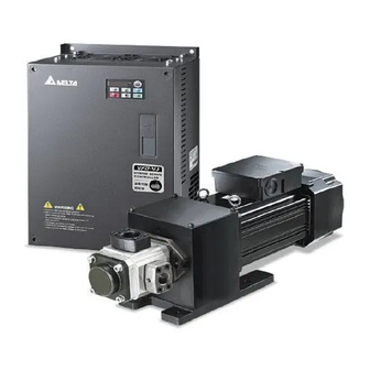
- Page 2 Preface Thank you for choosing the Hybrid Energy System (HES) designed exclusively for the Delta Injection Machine, which consists of Hybrid Servo Controller (VFD-VJ) series and servo oil pump. These production instructions provide the users with complete information regarding the installation, parameter configuration, anomaly diagnosis, troubleshooting, and routine maintenance of the Hybrid Servo Driver.
- Page 3 Since our products are being constantly improved, for information about any changes in specifications, please contact our local agents or visit ( http://www.delta.com.tw/industrialautomation/ ) to download the most recent versions. Call 1(800)985-6929 for Sales deltaacdrives.com...
-
Page 4: Table Of Contents
Call 1(800)985-6929 for Sales deltaacdrives.com sales@deltaacdrives.com Table of Contents Chapter 1 Use and Installation 1-1 Exterior of Product ........................ 1-2 1-2 Specifications........................1-3 1-3 Introduction of Hybrid Energy System................... 1-5 1-4 Installation ..........................1-6 1-5 Dimensions........................... 1-9 Chapter 2 Wiring 2-1 Wiring ........................... - Page 5 Call 1(800)985-6929 for Sales deltaacdrives.com sales@deltaacdrives.com 5-3-7 Phase Loss (PHL)..................... 5-10 5-3-8 Resolutions for Electromagnetic Noise and Induction Noise........5-11 5-3-9 Environment and Facilities for Installation ..............5-12 Chapter 6 Maintenance Regular Maintenance ........................6-2 Appendix A. Instructions of Product Packaging A-1 Descriptions of Product Packaging ..................A-2 A-2 Detailed List of Product Packaging ..................A-3 Appendix B Optional Accessories...
-
Page 6: Chapter 1 Use And Installation
Call 1(800)985-6929 for Sales deltaacdrives.com sales@deltaacdrives.com Chapter 1 Use and Installation|HES Series Chapter 1 Use and Installation 1-1 Exterior of Product 1-2 Product Specifications 1-3 Introduction of Hybrid Energy System 1-4 Product Installation 1-5 Product Dimensions Upon receipt of the product, the clients are advised to keep the product in its original packaging box. If... -
Page 7: Exterior Of Product
Call 1(800)985-6929 for Sales deltaacdrives.com sales@deltaacdrives.com Chapter 1 Use and Installation|HES Series 1-1 Exterior of Product All Hybrid Energy System has passed strict quality control before being shipped out from the factory, with enforced packaging that sustains impacts. Upon opening the packaging of the Hybrid Energy System, the customers are recommended to conduct the examination by the following steps: Check if there is any damage to Hybrid Energy System during shipping. -
Page 8: Specifications
Call 1(800)985-6929 for Sales deltaacdrives.com sales@deltaacdrives.com Chapter 1 Use and Installation|HES Series 1-2 Specifications 230V Series Specifications HES____23A Model Number 063H 080G 080H 100G 100H 100Z 125G 125H 160G Oil Pump Capacity cc/rev Flow Rate L/min Maximum Flow Rate* L/min... - Page 9 Call 1(800)985-6929 for Sales deltaacdrives.com sales@deltaacdrives.com Chapter 1 Use and Installation|HES Series 460V Series Specifications HES____43A Model Number 063G 063H 080G 080H 100G 100H 100Z 125G 125H 160G 160H 200G Oil Pump Capacity cc/rev Flow rate Flow Rate L/min Specifications...
-
Page 10: Introduction Of Hybrid Energy System
Call 1(800)985-6929 for Sales deltaacdrives.com sales@deltaacdrives.com Chapter 1 Use and Installation|HES Series 1-3 Introduction of Hybrid Energy System Pressure Command Delta Hybrid (0~10V) Injector Servo Pressure Controller Controller Sensor Flow Rate Command (0~10V) PG Card U V W Over heat protection... -
Page 11: Installation
Call 1(800)985-6929 for Sales deltaacdrives.com sales@deltaacdrives.com Chapter 1 Use and Installation|HES Series 1-4 Installation Servo Oil Pump Please install the servo oil pump in an environment with the following conditions to ensure safe product operation: Conditions of Operation Environment Temperature 0°C~ 40°C... - Page 12 Call 1(800)985-6929 for Sales deltaacdrives.com sales@deltaacdrives.com Chapter 1 Use and Installation|HES Series Pipelines & Connections Remove all protection caps on the pump Choose suitable oil tube and connectors (Maximum intake flow rate 1m/s) Recommended Specifications of intake oil tube Flow Rate(L/min)
- Page 13 Call 1(800)985-6929 for Sales deltaacdrives.com sales@deltaacdrives.com Chapter 1 Use and Installation|HES Series mm (inch) mm (inch) 7.5-20HP 75 (3) 175 (7) 25-75HP 75 (3) 200 (8) 100HP 75 (3) 250 (10) The Hybrid Servo Controller must be installed vertically with screws to sturdy structures. Do not install it upside down, tilted, or horizontally.
-
Page 14: Dimensions
Call 1(800)985-6929 for Sales deltaacdrives.com sales@deltaacdrives.com Chapter 1 Use and Installation|HES Series 1-5 Dimensions Servo Oil Pump HES063H23A, HES063G43A, HES063H43A, HES080G23A, HES080H23A, HES080G43A, HES080H43A HES100G23A, HES100H23A, HES100G43A, HES100H43A HES125G23A, HES125H23A, HES125G43A, HES125H43A Call 1(800)985-6929 for Sales deltaacdrives.com sales@deltaacdrives.com... - Page 15 Call 1(800)985-6929 for Sales deltaacdrives.com sales@deltaacdrives.com Chapter 1 Use and Installation|HES Series HES160G23A, HES160G43A, HES160H43A HES160H43A HES200G43A 1-10 Call 1(800)985-6929 for Sales deltaacdrives.com sales@deltaacdrives.com...
- Page 16 Call 1(800)985-6929 for Sales deltaacdrives.com sales@deltaacdrives.com Chapter 1 Use and Installation|HES Series Hybrid Servo Controller Frame C Unit: mm[inch] Frame Ø Ø1 Ø2 Ø3 [9.25] [8.03] [13.78] [13.27] [12.60] [5.35] [0.26] [1.34] [0.87] NOTE Frame C: VFD110VL23A/43A-J, 1-11 Call 1(800)985-6929 for Sales deltaacdrives.com...
- Page 17 Call 1(800)985-6929 for Sales deltaacdrives.com sales@deltaacdrives.com Chapter 1 Use and Installation|HES Series Frame D Unit: mm[inch] Frame Ø Ø1 Ø2 Ø3 255.0 226.0 403.8 384.0 360.0 21.9 168.0 [10.04] [8.90] [15.90] [15.12] [14.17] [0.86] [6.61] [0.33] [1.73] [1.34] [0.87] NOTE...
- Page 18 Call 1(800)985-6929 for Sales deltaacdrives.com sales@deltaacdrives.com Chapter 1 Use and Installation|HES Series Frame E Unit: mm[inch] Frame 370.0 335.0 589.0 560.0 260.0 132.5 18.0 13.0 13.0 18.0 [14.57] [13.19] [23.19] [22.05] [10.24] [5.22] [0.71] [0.51] [0.51] [0.71] 370.0 335.0 595.0 589.0...
-
Page 19: Chapter 2 Wiring
Call 1(800)985-6929 for Sales deltaacdrives.com sales@deltaacdrives.com Chapter 2 Wiring|HES Series Chapter 2 Wiring 2-1 Wiring 2-2 Wiring of Servo Oil Pump 2-3 Descriptions of Main circuit Terminals 2-4 Descriptions of Control Loop Terminals Upon opening the top cover of the Hybrid Servo Controller and reveal the wiring terminal bus, check if the terminals of each Main circuit circuit and control loop circuit are labeled clearly. - Page 20 Call 1(800)985-6929 for Sales deltaacdrives.com sales@deltaacdrives.com Chapter 2 Wiring|HES Series 2-1 Wiring The wiring of the hybrid energy system consists of that for the servo oil pump and that for the Hybrid Servo Controller. The user must follow the wiring loop below for all wire connections.
- Page 21 Call 1(800)985-6929 for Sales deltaacdrives.com sales@deltaacdrives.com Chapter 2 Wiring|HES Series Note 1* For models with power rating below 22kW For models with power rating above 30kW (including the 22kW model, with built-in brake (including the 30kW model, brake unit is...
- Page 22 Call 1(800)985-6929 for Sales deltaacdrives.com sales@deltaacdrives.com Chapter 2 Wiring|HES Series Multi-pump Operation Mode Combined Mode Master Slave Pressure Pressure F eedback Command Combine Command Hydraulic Pump Activation EM VJ-M F01 EM VJ-MF0 1 M otion Com mand IN.PWR. SINK Combined-Divert Mode...
-
Page 23: Wiring Of Servo Oil Pump
Call 1(800)985-6929 for Sales deltaacdrives.com sales@deltaacdrives.com Chapter 2 Wiring|HES Series 2-2 Wiring of Servo oil Pump Electric Box Delta Hydraulic Servo Motor Corresponding to Controller PG Card Hydraulic Servo Motor Controller U V W (Crimp Terminal Temperature Rise Specification as... - Page 24 Call 1(800)985-6929 for Sales deltaacdrives.com sales@deltaacdrives.com Chapter 2 Wiring|HES Series External Wiring of Hybrid Servo Controller Power Supply Power Please follow the power rating listed in the Supply user's manual (chapter 1) A larger current may be generated when the...
- Page 25 Call 1(800)985-6929 for Sales deltaacdrives.com sales@deltaacdrives.com Chapter 2 Wiring|HES Series 2-3 Main Circuit Terminal Label Description R/L1, S/L2, T/L3 AC line input terminals U/T1, V/T2, W/T3 Output of Hybrid Servo Controller, connected to hybrid servo motor For power improvement of the connection terminal of DC reactor. Please...
- Page 26 Call 1(800)985-6929 for Sales deltaacdrives.com sales@deltaacdrives.com Chapter 2 Wiring|HES Series To avoid lightning strike and incidence of electrocution, the external metal ground wire for the electrical equipments must be thick and short and connected to the ground terminal of the Hybrid servo driver system.
- Page 27 Call 1(800)985-6929 for Sales deltaacdrives.com sales@deltaacdrives.com Chapter 2 Wiring|HES Series Please use isolation wire or wire tube for power supply wiring and ground the isolation layer or both ends of wire tube. Output terminals for main circuit (U, V, W) : The output side of Hybrid Servo Controller cannot be connected with advance phase capacitor, surge absorber, advance phase capacitor, or L-C and R-C filters.
- Page 28 Call 1(800)985-6929 for Sales deltaacdrives.com sales@deltaacdrives.com Chapter 2 Wiring|HES Series Main Circuit Terminals Frame C Main circuit terminals: R/L1, S/L2, T/L3, U/T1, V/T2, W/T3, , +1, +2/B1, -, B2 Model Wire Gauge Torque VFD055VL23A-J 10-6 AWG. (5.3-13.3mm VFD110VL43A-J VFD055VL43A-J 12-6 AWG. (3.3-13.3mm...
- Page 29 Call 1(800)985-6929 for Sales deltaacdrives.com sales@deltaacdrives.com Chapter 2 Wiring|HES Series Frame E Main circuit terminals: R/L1, S/L2, T/L3, U/T1, V/T2, W/T3, , +1, +2, - Model Wire Gauge Torque VFD300VL43A-J 57kgf-cm VFD370VL43A-J (49in-lbf) VFD450VL43A-J 4-2 AWG. VFD300VL23A-J (21.2-33.6mm VFD370VL23A-J 200kgf-cm...
- Page 30 Call 1(800)985-6929 for Sales deltaacdrives.com sales@deltaacdrives.com Chapter 2 Wiring|HES Series +E24V The position of the External Terminals Sink/Source Mode Switch Terminal +10V MO1 MO2 +24V Frame Torque Wire Gauge C, D, E 8 kgf-com (6.9 in-lbf) 22-14 AWG (0.3-2.1mm Terminal: 0V/24V 1.6 kgf-com(1.4 in-lbf)
- Page 31 Call 1(800)985-6929 for Sales deltaacdrives.com sales@deltaacdrives.com Chapter 2 Wiring|HES Series Factory Setting (NPN mode) Terminal Function Pressure Feedback PO/PI/QI circuit Impedance:200kΩ Resolution:12 bits PO/PI/QI Circuit PO/PI/QI Range:0 10V=0~maximum Pressure Feedback value(Pr.00-08) Pressure Command Impedance:200kΩ Resolution:12 bits Range:0 10V=0~maximum pressure command value(Pr.00-07)
- Page 32 Call 1(800)985-6929 for Sales deltaacdrives.com sales@deltaacdrives.com Chapter 2 Wiring|HES Series Transistor outputs (MO1, MO2, MCM) Make sure to connect the digital outputs to the right polarity. When connecting a relay to the digital outputs connect a surge absorber across the coil and check the polarity.
- Page 33 Call 1(800)985-6929 for Sales deltaacdrives.com sales@deltaacdrives.com Chapter 3 Flow of machine Adjustment|HES Series Chapter 3 Start Up 3-1 Digital Keypad KPVJ-LE01 3-2 Auto-tuning Operations 3-3 Explanations for the Auto-tuning Steps Please verify again before operation that the wiring is done correctly, especially that the output terminals U/T1, V/T2, and W/T3 of the Hybrid Servo Controller cannot have any power input.
- Page 34 Call 1(800)985-6929 for Sales deltaacdrives.com sales@deltaacdrives.com Chapter 3 Flow of machine Adjustment|HES Series 3-1 Digital Keypad (KPVJ-LE01) Description of the Digital Keypad KPVJ-LE01 Run key start AC drive operation Stop/Reset key Stop driver operation and reset in case of anomaly Sta tus Display Disp lay the dr iver ’s cur re nt status.
- Page 35 Call 1(800)985-6929 for Sales deltaacdrives.com sales@deltaacdrives.com Chapter 3 Flow of machine Adjustment|HES Series Display Message Descriptions External Fault. Display “End” for approximately 1 second if input has been accepted by pressing key. After a parameter value has been set, the new value is automatically stored in memory.
- Page 36 Call 1(800)985-6929 for Sales deltaacdrives.com sales@deltaacdrives.com Chapter 3 Flow of machine Adjustment|HES Series Reference Table for the 7-segment LED Display of the Digital Keypad Number Seven Segment Display English letter Seven Segment - - - - Display English letter Seven Segment -...
- Page 37 Call 1(800)985-6929 for Sales deltaacdrives.com sales@deltaacdrives.com Chapter 3 Flow of machine Adjustment|HES Series 3-2 Auto-tuning Flow Chart Set the gasoline-electric servo motor code Check if the pressure Troubleshoot feedback signal is normal Y E S Calibrate pressure and flow commands...
- Page 38 Call 1(800)985-6929 for Sales deltaacdrives.com sales@deltaacdrives.com Chapter 3 Flow of machine Adjustment|HES Series 3-3 Explanations for the Auto-tuning Steps Operate the following steps with the digital operator (KPVJ-LE01/ KPV-CE01) or the VFD-Explorer monitor software Prior to starting running, please verify again if the wiring is correct, especially that the output terminals U/T1, V/T2, and W/T3 of the Hybrid Servo Controller must correspond to the U, V, and W terminals of the gasoline-electric servo motor, respectively.
- Page 39 Call 1(800)985-6929 for Sales deltaacdrives.com sales@deltaacdrives.com Chapter 3 Flow of machine Adjustment|HES Series Step 3.Check Pressure Feedback Signal Firs, set input voltage Pr. 00-04 = 11 PO Selection of Display Mode Pr. 00-04 11: Display the signal of PO analog input terminal, with 0~10V corresponding to 0~100%.
- Page 40 Call 1(800)985-6929 for Sales deltaacdrives.com sales@deltaacdrives.com Chapter 3 Flow of machine Adjustment|HES Series on the operation panel and set it to 00-16. Example: 10V on the pressure sensor corresponds to 250bar. If the maximum pressure on the controller is 140bar and corresponds to 10V, the Pr. 00-07=140. Set 140bar through the controller and the voltage reading displayed on the operation panel is approximately 56.0(140/250*100%).
- Page 41 Call 1(800)985-6929 for Sales deltaacdrives.com sales@deltaacdrives.com Chapter 3 Flow of machine Adjustment|HES Series leaking and for any noise in the oil pump. When the air is vented completely, if there is any pressure fluctuation while the system is in action, please refer to the methods listed in the "Descriptions of Parameters" to adjust the pressure control PI parameter.
- Page 42 Call 1(800)985-6929 for Sales deltaacdrives.com sales@deltaacdrives.com Chapter 3 Flow of machine Adjustment|HES Series the bold red lines in the figure below). If the shielding mesh is grounded, disconnect the ground wire. If the shielding mesh is not grounded, add the ground wire for interference protection.
- Page 43 Call 1(800)985-6929 for Sales deltaacdrives.com sales@deltaacdrives.com Chapter 3 Flow of machine Adjustment|HES Series Configuration Flow of Combined System Follow the associated descriptions in Chapter 2 to lay out the wiring. Follow steps 1 and 2 described above to enter the electrical codes for the master/slave machines.
-
Page 44: Steps Of System Configuration Flow
Call 1(800)985-6929 for Sales deltaacdrives.com sales@deltaacdrives.com Chapter 3 Flow of machine Adjustment|HES Series Pr. 03-13 0: No function 1: Master station 2: Slave station Resume power supply to slave machine after power outage Set slave machine to speed control mode Pr. -
Page 45: Chapter 4 Parameter Functions
Call 1(800)985-6929 for Sales deltaacdrives.com sales@deltaacdrives.com |HES Series Chapter 4 Parameter Functions Chapter 4 Parameters 4-1 Summary of Parameter Settings 4-2 Description of Parameter Settings Call 1(800)985-6929 for Sales deltaacdrives.com sales@deltaacdrives.com... - Page 46 Call 1(800)985-6929 for Sales deltaacdrives.com sales@deltaacdrives.com |HES Series Chapter 4 Parameter Functions 4-1 Summary of Parameter Settings 00 System Parameters : The parameter can be set during operation. Factory Explanation Settings Setting 00-00 Identity Code of the Hybrid 12: 230V, 7.5HP...
- Page 47 Call 1(800)985-6929 for Sales deltaacdrives.com sales@deltaacdrives.com |HES Series Chapter 4 Parameter Functions Factory Explanation Settings Setting 00-04 Content of Multi-function Display 0: Displays the output current (A) from Hybrid Servo Controller to motor. Reserved Displays the actual output frequency (H) of the Hybrid Servo Controller.
- Page 48 Call 1(800)985-6929 for Sales deltaacdrives.com sales@deltaacdrives.com |HES Series Chapter 4 Parameter Functions Factory Explanation Settings Setting 00-12 Pressure Command Filter Time 0.000~1.000 sec 0.000 ○ ○ ○ 00-13 Flow Command Filter Time QI 0.000~1.000 sec 0.000 ○ ○ ○ 00-14 Pressure Command Percentage 0.0~100.0%...
- Page 49 0.00~655.35mH 0.00 ○ 01-25 Ke parameter of PM Motor 0~65535 V/krpm ○ 01-26 Encoder Type 0: ABZ 1: ABZ+HALL (for Delta motors only) ○ 2: ABZ+HALL 3: Resolver 01-27 PG Offset angle of PM Motor 0.0~360.0° ○ 01-28 Resolver Poles ○...
- Page 50 5KHz; 10KHz ○ ○ ○ 01-34 Reserved 01-35 Hydraulic Servo Motor ID 0: No function 16: Delta Hydraulic Servo Motor Model #ECMA-ER181BP3 (11kW220V) 17 :Delta Hydraulic Servo Motor Model #ECMA-KR181BP3 (11kW380V) 18: Delta Hydraulic Servo Motor Model ○ ○ ○...
- Page 51 Call 1(800)985-6929 for Sales deltaacdrives.com sales@deltaacdrives.com |HES Series Chapter 4 Parameter Functions 02 Protection Parameters : The parameter can be set during operation. Factory Explanation Settings Setting 02-00 Software Brake Level 230V Series: 350.0~450.0Vdc 380.0 ○ ○ ○ 460V Series: 700.0~900.0Vdc 760.0...
- Page 52 Call 1(800)985-6929 for Sales deltaacdrives.com sales@deltaacdrives.com |HES Series Chapter 4 Parameter Functions Factory Explanation Settings Setting 49: External fault input (EF) ○ ○ ○ 50: Emergency stop (EF1) ○ ○ ○ 51: Reserved 52: Password error (PcodE) ○ ○ ○...
- Page 53 Call 1(800)985-6929 for Sales deltaacdrives.com sales@deltaacdrives.com |HES Series Chapter 4 Parameter Functions 03 Digital/Analog I/O Parameters : The parameter can be set during operation. Factory Explanation Settings Setting Multi-functional Input Command 03-00 ○ ○ ○ 3 (MI3) 0: No function...
- Page 54 Call 1(800)985-6929 for Sales deltaacdrives.com sales@deltaacdrives.com |HES Series Chapter 4 Parameter Functions 4-2 Description of Parameter Settings 00 System Parameters : The parameter can be set during operation. Identity Code of the Hybrid Servo Controller Factory setting: ## Control Mode...
- Page 55 Call 1(800)985-6929 for Sales deltaacdrives.com sales@deltaacdrives.com |HES Series Chapter 4 Parameter Functions 6: Displays the output power kW (P) of the Hybrid Servo Controller. 7: Displays the motor speed (rpm, r) estimated by the Hybrid Servo Controller or fed back from the encoder. (r00: Positive Forward Speed;...
- Page 56 Call 1(800)985-6929 for Sales deltaacdrives.com sales@deltaacdrives.com |HES Series Chapter 4 Parameter Functions 12-20 Reserved User-defined: Display actual motor speed in rpm Factory setting: 0 Control Mode FOCPG FOCPM Settings 0~39999rpm Sets the hydraulic motor speed at 100% flow. Maximum Value of Pressure Command...
- Page 57 Call 1(800)985-6929 for Sales deltaacdrives.com sales@deltaacdrives.com |HES Series Chapter 4 Parameter Functions Pressure Command Percentage (MAX) Pressure Command Percentage (Mid) Pressure Command Percentage (Min) Factory setting: 100.0 Control Mode FOCPG FOCPM Settings 0.0~100.0% Set the Pr.00-09 to “1” before setting these parameters.
- Page 58 Call 1(800)985-6929 for Sales deltaacdrives.com sales@deltaacdrives.com |HES Series Chapter 4 Parameter Functions Integral Time 3 (I) Factory setting: 2.00 Control Mode FOCPG FOCPM Settings 0.00~500.00 sec Derivative Gain Factory setting: 0.0 Control Mode FOCPG FOCPM Settings 0.0~100.0 % Pressure Stabilization Zone...
- Page 59 Call 1(800)985-6929 for Sales deltaacdrives.com sales@deltaacdrives.com |HES Series Chapter 4 Parameter Functions Bottom Pressure Factory setting: 1.0 Control Mode FOCPG FOCPM Settings 0.0~100.0% Sets the lowest pressure; 100% corresponds to Pr.00-08. In general, bottom pressure at a certain degree must be reserved to ensure that there is oil inside the oil pipelines.
- Page 60 Call 1(800)985-6929 for Sales deltaacdrives.com sales@deltaacdrives.com |HES Series Chapter 4 Parameter Functions begins. As the valve opening action responds rather slowly, pressure surges instantaneously and returns to normal until the valve opens completely. In order to prevent this phenomenon, users can set the value open delay time to delay the flow output.
- Page 61 Call 1(800)985-6929 for Sales deltaacdrives.com sales@deltaacdrives.com |HES Series Chapter 4 Parameter Functions 01 Motor Parameters : The parameter can be set during operation. Control Mode Factory setting: 5 Control Mode FOCPG FOCPM Settings 0: V/F Control 1: Reserved 2: Reserved...
- Page 62 Call 1(800)985-6929 for Sales deltaacdrives.com sales@deltaacdrives.com |HES Series Chapter 4 Parameter Functions nominal voltage for motor operation. If the motor voltage is 220V, set the value to 220.0V. If the motor voltage frequency is 200V, set the value to 200.0V.
- Page 63 Call 1(800)985-6929 for Sales deltaacdrives.com sales@deltaacdrives.com |HES Series Chapter 4 Parameter Functions Pr .01-16 Pr. 01-1 3 Pr. 01-14 Pr.01-15 M otor e quivalent circuit used by VJ NOTE When running static tuning (Pr.01-07 = 2), users must input the no-load current to the motor. In general, the current is 20-50% of the nominal current.
- Page 64 Call 1(800)985-6929 for Sales deltaacdrives.com sales@deltaacdrives.com |HES Series Chapter 4 Parameter Functions The range available for adjustment is 10A to 30A. 25*40%=10 25*120%=30 Rated power of Motor (kW) (IM) Factory setting: #.## Control Mode FOCPG Settings 0~655.35 kW Sets the motor nominal power. Default is the driver’s nominal power.
- Page 65 Settings 0~65535 V/krpm Input the BEMF of the permanent motor. Encoder Type Factory setting: 3 Control Mode FOCPM Settings 0: ABZ 1: ABZ+HALL (for use on Delta motor only) 2: ABZ+HALL 3: Resolver 4-21 Call 1(800)985-6929 for Sales deltaacdrives.com sales@deltaacdrives.com...
- Page 66 Call 1(800)985-6929 for Sales deltaacdrives.com sales@deltaacdrives.com |HES Series Chapter 4 Parameter Functions Encoder & PG Card Cross-Reference Table Parameter Setting Encoder Type Suitable PG Card 01-26=0 A, B, Z EMVJ-PG01U 01-26=1,2 A, B, Z+U, V, W EMVJ-PG01U 01-26=3 Resolver EMVJ-PG01/02R PG offset angle of PM Motor Factory setting: 0.0...
- Page 67 Control Mode FOCPG FOCPM Settings 0 : No function 16: Delta Hydraulic Servo Motor Model #ECMA-ER181BP3 (11kW220V) 17 :Delta Hydraulic Servo Motor Model #ECMA-KR181BP3 (11kW380V) 18: Delta Hydraulic Servo Motor Model #ECMA-ER221FPS (15kW220V) 19: Delta Hydraulic Servo Motor Model #ECMA-KR221FPS (15kW380V)
- Page 68 Call 1(800)985-6929 for Sales deltaacdrives.com sales@deltaacdrives.com |HES Series Chapter 4 Parameter Functions 1: When the driver runs forward, the motor rotates clockwise. When the driver runs backward, the motor rotates counterclockwise. Rotation direction can only be changed when the system is shutdown. After setting the inductor parameters, the rotation direction changes immediately.
- Page 69 Call 1(800)985-6929 for Sales deltaacdrives.com sales@deltaacdrives.com |HES Series Chapter 4 Parameter Functions 02 Protection Parameters : The parameter can be set during operation. Software Brake Transistor Action Reference Point Setup Factory setting: 380.0/760.0 Control Mode FOCPG FOCPM Settings 230VSeries: 350.0~450.0Vdc 460VSeries: 700.0~900.0Vdc...
- Page 70 Call 1(800)985-6929 for Sales deltaacdrives.com sales@deltaacdrives.com |HES Series Chapter 4 Parameter Functions 26: over-torque 1 (ot1) ○ ○ ○ 27: over-torque 2 (ot2) ○ ○ ○ 28: Reserved 29: Reserved 30: Memory write-in error (cF1) 31: Memory read-out error (cF2) ○...
- Page 71 Call 1(800)985-6929 for Sales deltaacdrives.com sales@deltaacdrives.com |HES Series Chapter 4 Parameter Functions Low Voltage Reference Point Factory setting: 180/360 Control Mode FOCPG FOCPM Settings 230V Models: 160~220V 460V Models: 320~440V Sets the reference point for LV judgment. I nput Volt age...
- Page 72 Call 1(800)985-6929 for Sales deltaacdrives.com sales@deltaacdrives.com |HES Series Chapter 4 Parameter Functions activated or stopped at this point. Thermoelectric Relay 1 Options Factory setting: 2 Control Mode FOCPG FOCPM Settings 0: Inverter Motor 1: Standard Motor 2: No thermoelectric relay Thermoelectric Relay 1 Action Time Factory setting: 60.0...
- Page 73 Call 1(800)985-6929 for Sales deltaacdrives.com sales@deltaacdrives.com |HES Series Chapter 4 Parameter Functions 03 Digital/Analog I/O Parameters : The parameter can be set during operation. Multi-function Input Command 3 (MI3) Multi-function Input Command 4 (MI4) Multi-function Input Command 5 (MI5) Factory setting: 0...
- Page 74 Call 1(800)985-6929 for Sales deltaacdrives.com sales@deltaacdrives.com |HES Series Chapter 4 Parameter Functions 44: Ram pump flow switch signal 45: Motor fan control signal Multi-function Output Direction Factory setting: 0 Control Mode FOCPG FOCPM Settings 0~65535 This parameter is bit setting. If the bit is 1, the multi-function output terminal will be act with opposite direction.
- Page 75 Call 1(800)985-6929 for Sales deltaacdrives.com sales@deltaacdrives.com |HES Series Chapter 4 Parameter Functions Source Setup of the Master Frequency Command Factory setting: 0 Control Mode FOCPG FOCPM Settings 0: Digital keypad 1: RS485 serial communication 2~5: Reserved This must be worked with EMVJ-MF01. Please refer to the tuning description in Chapter 3.
-
Page 76: Chapter 5 Methods Of Anomaly Diagnosis
Call 1(800)985-6929 for Sales deltaacdrives.com sales@deltaacdrives.com |HES Series Chapter 5 Methods of Anomaly Diagnosis Chapter 5 Methods of Anomaly Diagnosis 5-1 System Troubleshooting 5-2 Signal Display of Hybrid Servo Controller 5-2-1 Indicator Display 5-2-2 Error Messages Displayed on Digital Operation Panel... - Page 77 Call 1(800)985-6929 for Sales deltaacdrives.com sales@deltaacdrives.com Call 1(800)985-6929 for Sales deltaacdrives.com sales@deltaacdrives.com...
-
Page 78: System Troubleshooting
Call 1(800)985-6929 for Sales deltaacdrives.com sales@deltaacdrives.com |HES Series Chapter 5 Methods of Anomaly Diagnosis 5-1 System Troubleshooting Check if hybrid servo motor is running Failure to establish pressure Check if the coupling is loose or breaking off Check for any leak in the oil line... - Page 79 Call 1(800)985-6929 for Sales deltaacdrives.com sales@deltaacdrives.com |VJ Series Chapter 5 Methods of Anomaly Diagnosis In d ic a to r o f P G c ard p o we r P ower ind ic a tor In d ic ato r o f E n c o de r fe ed b a c k P ower ind ic a tor Wa rn ing ind ic a tor W h en th e s in o r c o s p ha s e v o lta ge is lo we r th a n req u ired v a lu e s in th e ro ta tio na l...
- Page 80 Call 1(800)985-6929 for Sales deltaacdrives.com sales@deltaacdrives.com |HES Series Chapter 5 Methods of Anomaly Diagnosis 5-2-2 Error Messages Displayed on Digital Operation Panel KPVJ-LE01 Display Code Description of Anomaly Troubleshooting Check if the insulation of the wire from U-V-W Over current...
- Page 81 Call 1(800)985-6929 for Sales deltaacdrives.com sales@deltaacdrives.com |VJ Series Chapter 5 Methods of Anomaly Diagnosis the AC side fuse is blown Ground wire protection, applies when Hybrid Servo Controller Check the wire of hybrid servo motor is detects the output is grounded and shorted or grounded the ground current is higher than Check if IGBT power module is damaged...
- Page 82 Call 1(800)985-6929 for Sales deltaacdrives.com sales@deltaacdrives.com |HES Series Chapter 5 Methods of Anomaly Diagnosis Abnormal in OH1 hardware wire Send back to manufacturer for repair Abnormal in OH2 hardware wire Send back to manufacturer for repair Abnormal cc protection hardware...
- Page 83 Call 1(800)985-6929 for Sales deltaacdrives.com sales@deltaacdrives.com |VJ Series Chapter 5 Methods of Anomaly Diagnosis KPV-CE01 EXT PU STOP RESET Call 1(800)985-6929 for Sales deltaacdrives.com sales@deltaacdrives.com...
-
Page 84: Steps Of Troubleshooting For Hybrid Servo Controller
Call 1(800)985-6929 for Sales deltaacdrives.com sales@deltaacdrives.com |HES Series Chapter 5 Methods of Anomaly Diagnosis 5-3 Steps of Troubleshooting for Hybrid Servo Controller 5-3-1 Over Current (OC) over current over current in Over current in while running at deceleration acceleration constant speed... -
Page 85: Over Voltage (Ov)
If Lv occurs when the circuit If the capacity of power supply breaker and electromagnetic transformer is appropriate contactor are ON It's likely hybrid servo controller breaks down or malfunctions due to noise. Please contact Delta for assistance. Call 1(800)985-6929 for Sales deltaacdrives.com sales@deltaacdrives.com... -
Page 86: Overheat (Oh1)
Heat sink is overheated Temperature detection circuit on Is the temperature of heat sink circuit board malfunctions. Please higher than 90°C contact Delta for assistance. Reduce load Is load too heavy Is cooling fan running Replace cooling fan Remove the clog... -
Page 87: Phase Loss (Phl)
Please check wiring and Is voltage of the three phase power system for power supply unbalanced abnormal behavior It's likely hybrid servo controller breaks down or malfunctions due to noise. Please contact Delta for assistance. 5-10 Call 1(800)985-6929 for Sales deltaacdrives.com sales@deltaacdrives.com... - Page 88 Call 1(800)985-6929 for Sales deltaacdrives.com sales@deltaacdrives.com |HES Series Chapter 5 Methods of Anomaly Diagnosis 5-3-8 Electromagnetic/Induction Noise If there exist noise sources around Hybrid Servo Controller, they will affect Hybrid Servo Controller through radiation or the power lines, leading to malfunction of control loop and causing tripping or even damage of Hybrid Servo Controller.
-
Page 89: Environment And Facilities For Installation
Call 1(800)985-6929 for Sales deltaacdrives.com sales@deltaacdrives.com |VJ Series Chapter 5 Methods of Anomaly Diagnosis 5-3-9 Environment and Facilities for Installation The Hybrid Servo Controller is a device for electronic components. Detailed descriptions of the environment suitable for its operation can be found in the specifications. If the listed regulations cannot be followed for any reason, there must be corresponding remedial measures or contingency solutions. -
Page 90: Chapter 6 Maintenance
Call 1(800)985-6929 for Sales deltaacdrives.com sales@deltaacdrives.com Chapter 6 Maintenance|HES Series Chapter 6 Maintenance Maintenance and Inspections The AC motor drive has a comprehensive fault diagnostic system that includes several different alarms and fault messages. Once a fault is detected, the corresponding protective functions will be activated. - Page 91 Call 1(800)985-6929 for Sales deltaacdrives.com sales@deltaacdrives.com Chapter 6 Maintenance|HES Series Maintenance and Inspections Before the check-up, always turn off the AC input power and remove the cover. Wait at least 10 minutes after all display lamps have gone out, and then confirm that the capacitors have fully discharged by measuring the voltage between DC+ and DC-.
- Page 92 Call 1(800)985-6929 for Sales deltaacdrives.com sales@deltaacdrives.com Chapter 6 Maintenance|HES Series Mechanical parts Period of inspection Check Items Methods and Criterion Daily Half year Year Visual and aural ○ If there is any abnormal sound or vibration inspection If there are any loose screws Tighten the screws ○...
- Page 93 Call 1(800)985-6929 for Sales deltaacdrives.com sales@deltaacdrives.com Chapter 6 Maintenance|HES Series Main Circuit~Resistor Period of inspection Check Items Method of Inspection Daily Half year Year Is there any odor from overheating and breaking Visual inspection and ○ of insulation? listening Is there any open circuit? Visual inspection ○...
- Page 94 Call 1(800)985-6929 for Sales deltaacdrives.com sales@deltaacdrives.com Chapter 6 Maintenance|HES Series Cooling System~Air Duct Period of inspection Check Items Method of Inspection Daily Half year Year Is the heatsink, the inlet and exhaust unclogged Aural inspection ○ and free of foreign objects? NOTE To treat the contaminated spots, please wipe clean with cloths that is chemically neutral.
-
Page 95: Appendix A. Instructions Of Product Packaging
Call 1(800)985-6929 for Sales deltaacdrives.com sales@deltaacdrives.com Appendix A. Instructions of Product Packaging|HES Series Appendix A. Instructions of Product Packaging A-1 Descriptions of Product packaging A-2 Detailed List of Product Packaging This product is made by a manufacturing process with strict quality control. If the product is damaged in the delivery by external force or crushing, please contact your local agents. -
Page 96: Descriptions Of Product Packaging
Call 1(800)985-6929 for Sales deltaacdrives.com sales@deltaacdrives.com Appendix A. Instructions of Product Packaging|HES Series A-1 Descriptions of Product Packaging Remove the packaging of the external box Models: Models: HES063H23A; HES080G23A; HES080H23A; HES125G23A; HES125G43A; HES100G23A; HES100H23A; HES063G43A;HES063H43A; HES080G43A; HES080H43A; HES100G43A; HES100H43A; Models: HES125H23A;... -
Page 97: Detailed List Of Product Packaging
Call 1(800)985-6929 for Sales deltaacdrives.com sales@deltaacdrives.com Appendix A. Instructions of Product Packaging|HES Series A-2 Detailed List of Product Packaging HES063H23A 1 Servo controller VFD110VL23A-J Unit: mm[inch] Ø Ø1 Ø2 Ø3 6.5 [0.26] 34 [1.34] 22 [0.87] [9.25] [8.03] [13.78] [13.27] [12.60]... - Page 98 Call 1(800)985-6929 for Sales deltaacdrives.com sales@deltaacdrives.com Appendix A. Instructions of Product Packaging|HES Series 3 Accessories Kit HESP-063-H-N-23 Component Model Number Quantity PG card EMVJ-PG02R ※ Braking resistor BR1K0W8P3 Coding device cable 5m Magnetic ring of power cable Sensor clamp ※ Braking resistor 1000W 8.3Ω...
- Page 99 Call 1(800)985-6929 for Sales deltaacdrives.com sales@deltaacdrives.com Appendix A. Instructions of Product Packaging|HES Series HES080G23A 1 Servo controller VFD110VL23A-J Unit: mm[inch] Ø Ø1 Ø2 Ø3 6.5 [0.26] 34 [1.34] 22 [0.87] [9.25] [8.03] [13.78] [13.27] [12.60] [5.35] 2 Servo oil pump HSP-032-110-23A...
- Page 100 Call 1(800)985-6929 for Sales deltaacdrives.com sales@deltaacdrives.com Appendix A. Instructions of Product Packaging|HES Series 3 Accessories Kit HESP-080-G-N-23 Component Model Number Quantity PG card EMVJ-PG02R BR1K0W8P3 ※ Braking resistor Coding device cable 5m Magnetic ring of power cable Sensor clamp ※ Braking resistor 1000W 8.3Ω...
- Page 101 Call 1(800)985-6929 for Sales deltaacdrives.com sales@deltaacdrives.com Appendix A. Instructions of Product Packaging|HES Series HES080H23A 1 Servo controller VFD150VL23A-J Unit: mm[inch] Ø Ø1 Ø2 Ø3 255.0 226.0 403.8 384.0 360.0 21.9 168.0 8.5 [0.33] 44 [1.73] 34 [1.34] 22 [0.87] [10.04] [8.90]...
- Page 102 Call 1(800)985-6929 for Sales deltaacdrives.com sales@deltaacdrives.com Appendix A. Instructions of Product Packaging|HES Series 3 Accessories Kit HESP-080-H-N-23 Component Model Number Quantity PG card EMVJ-PG02R BR1K0W5P8 ※ Braking resistor Coding device cable 5m Magnetic ring of power cable Sensor clamp ※ Braking resistor 1000W 5.8Ω...
- Page 103 Call 1(800)985-6929 for Sales deltaacdrives.com sales@deltaacdrives.com Appendix A. Instructions of Product Packaging|HES Series HES100G23A 1 Servo controller VFD150VL23A-J Unit: mm[inch] Ø Ø1 Ø2 Ø3 255.0 226.0 403.8 384.0 360.0 21.9 168.0 8.5 [0.33] 44 [1.73] 34 [1.34] 22 [0.87] [10.04] [8.90]...
- Page 104 Call 1(800)985-6929 for Sales deltaacdrives.com sales@deltaacdrives.com Appendix A. Instructions of Product Packaging|HES Series 3 Accessories Kit HESP-100-G-N-23 Component Model Number Quantity PG card EMVJ-PG02R BR1K0W5P8 ※ Braking resistor Coding device cable 5m Magnetic ring of power cable Sensor clamp ※ Braking resistor 1000W 5.8Ω...
- Page 105 Call 1(800)985-6929 for Sales deltaacdrives.com sales@deltaacdrives.com Appendix A. Instructions of Product Packaging|HES Series HES100H23A 1 Servo controller VFD185VL23A-J Unit: mm[inch] Ø Ø1 Ø2 Ø3 255.0 226.0 403.8 384.0 360.0 21.9 168.0 [10.04] [8.90] [15.90] [15.12] [14.17] [0.86] [6.61] [0.33] [1.73] [1.34]...
- Page 106 Call 1(800)985-6929 for Sales deltaacdrives.com sales@deltaacdrives.com Appendix A. Instructions of Product Packaging|HES Series 3 Accessories Kit HESP-100-H-N-23 Component Model Number Quantity PG card EMVJ-PG02R BR1K0W5P8 ※ Braking resistor Coding device cable 5m Magnetic ring of power cable Sensor clamp ※ Braking resistor 1000W 5.8Ω...
- Page 107 Call 1(800)985-6929 for Sales deltaacdrives.com sales@deltaacdrives.com Appendix A. Instructions of Product Packaging|HES Series HES125G23A 1 Servo controller VFD220VL23A-J Unit: mm[inch] Ø Ø1 Ø2 Ø3 255.0 226.0 403.8 384.0 360.0 21.9 168.0 [10.04] [8.90] [15.90] [15.12] [14.17] [0.86] [6.61] [0.33] [1.73] [1.34]...
- Page 108 Call 1(800)985-6929 for Sales deltaacdrives.com sales@deltaacdrives.com Appendix A. Instructions of Product Packaging|HES Series 3 Accessories Kit HESP-125-G-N-23 Component Model Number Quantity PG card EMVJ-PG02R BR2250W5P8 ※ Braking resistor Coding device cable 5m Magnetic ring of power cable Sensor clamp ※ Braking resistor 2250W 5.8Ω...
- Page 109 Call 1(800)985-6929 for Sales deltaacdrives.com sales@deltaacdrives.com Appendix A. Instructions of Product Packaging|HES Series HES125H23A 1 Servo controller VFD300VL23A-J Unit: mm[inch] 370.0 335.0 595.0 589.0 560.0 260.0 132.5 18.0 13.0 13.0 18.0 [14.57] [13.19] [23.43] [23.19] [22.05] [10.24] [5.22] [0.71] [0.51] [0.51]...
- Page 110 Call 1(800)985-6929 for Sales deltaacdrives.com sales@deltaacdrives.com Appendix A. Instructions of Product Packaging|HES Series 3 Accessories Kit HESP-125-H-B-23 Component Model Number Quantity PG card EMVJ-PG02R ※1 Braking unit VFDB-2022 BR2250W6P8 ※2 Braking resistor Coding device cable Magnetic ring of power Sensor clamp*1...
- Page 111 Call 1(800)985-6929 for Sales deltaacdrives.com sales@deltaacdrives.com Appendix A. Instructions of Product Packaging|HES Series HES160G23A 1 Servo controller VFD300VL23A-J Unit: mm[inch] 370.0 335.0 595.0 589.0 560.0 260.0 132.5 18.0 13.0 13.0 18.0 [14.57] [13.19] [23.43] [23.19] [22.05] [10.24] [5.22] [0.71] [0.51] [0.51]...
- Page 112 Call 1(800)985-6929 for Sales deltaacdrives.com sales@deltaacdrives.com Appendix A. Instructions of Product Packaging|HES Series 3 Accessories Kit HESP-160-G-B-23 Component Model Number Quantity PG card EMVJ-PG02R ※1 Braking unit VFDB-2022 BR2250W6P8 ※2 Braking resistor Coding device cable Magnetic ring of power Sensor clamp*1...
- Page 113 Call 1(800)985-6929 for Sales deltaacdrives.com sales@deltaacdrives.com Appendix A. Instructions of Product Packaging|HES Series HES063G43A 1 Servo controller VFD110VL43A-J Unit: mm[inch] Ø Ø1 Ø2 Ø3 6.5 [0.26] 34 [1.34] 22 [0.87] [9.25] [8.03] [13.78] [13.27] [12.60] [5.35] 2 Servo oil pump HSP-025-110-43A...
- Page 114 Call 1(800)985-6929 for Sales deltaacdrives.com sales@deltaacdrives.com Appendix A. Instructions of Product Packaging|HES Series 3 Accessories Kit HESP-063-G-N-43 Component Model Number Quantity PG card EMVJ-PG02R BR1K0W025 ※ Braking resistor Coding device cable 5m Magnetic ring of power cable Sensor clamp ※ Braking resistor 1000W 25Ω...
- Page 115 Call 1(800)985-6929 for Sales deltaacdrives.com sales@deltaacdrives.com Appendix A. Instructions of Product Packaging|HES Series HES063H43A 1 Servo controller VFD150VL43A-J Unit: mm[inch] Ø Ø1 Ø2 Ø3 255.0 226.0 403.8 384.0 360.0 21.9 168.0 [10.04] [8.90] [15.90] [15.12] [14.17] [0.86] [6.61] [0.33] [1.73] [1.34]...
- Page 116 Call 1(800)985-6929 for Sales deltaacdrives.com sales@deltaacdrives.com Appendix A. Instructions of Product Packaging|HES Series 3 Accessories Kit HESP-063-H-N-43 Component Model Number Quantity PG card EMVJ-PG02R BR1K0W025 ※ Braking resistor Coding device cable 5m Magnetic ring of power cable Sensor clamp ※ Braking resistor 1000W 25Ω...
- Page 117 Call 1(800)985-6929 for Sales deltaacdrives.com sales@deltaacdrives.com Appendix A. Instructions of Product Packaging|HES Series HES080G43A 1 Servo controller VFD150VL43A-J Unit: mm[inch] Ø Ø1 Ø2 Ø3 255.0 226.0 403.8 384.0 360.0 21.9 168.0 [10.04] [8.90] [15.90] [15.12] [14.17] [0.86] [6.61] [0.33] [1.73] [1.34]...
- Page 118 Call 1(800)985-6929 for Sales deltaacdrives.com sales@deltaacdrives.com Appendix A. Instructions of Product Packaging|HES Series 3 Accessories Kit HESP-080-G-N-43 Component Model Number Quantity PG card EMVJ-PG02R BR1K0W025 ※ Braking resistor Coding device cable 5m Magnetic ring of power cable Sensor clamp ※ Braking resistor 1000W 25Ω...
- Page 119 Call 1(800)985-6929 for Sales deltaacdrives.com sales@deltaacdrives.com Appendix A. Instructions of Product Packaging|HES Series HES080H43A 1 Servo controller VFD185VL43A-J Unit: mm[inch] Ø Ø1 Ø2 Ø3 255.0 226.0 403.8 384.0 360.0 21.9 168.0 [10.04] [8.90] [15.90] [15.12] [14.17] [0.86] [6.61] [0.33] [1.73] [1.34]...
- Page 120 Call 1(800)985-6929 for Sales deltaacdrives.com sales@deltaacdrives.com Appendix A. Instructions of Product Packaging|HES Series 3 Accessories Kit HESP-080-H-N-43 Component Model Number Quantity PG card EMVJ-PG02R BR1K0W025 ※ Braking resistor Coding device cable 5m Magnetic ring of power cable Sensor clamp ※ Braking resistor 1000W 25Ω...
- Page 121 Call 1(800)985-6929 for Sales deltaacdrives.com sales@deltaacdrives.com Appendix A. Instructions of Product Packaging|HES Series HES100G43A 1 Servo controller VFD185VL43A-J Unit: mm[inch] Ø Ø1 Ø2 Ø3 255.0 226.0 403.8 384.0 360.0 21.9 168.0 [10.04] [8.90] [15.90] [15.12] [14.17] [0.86] [6.61] [0.33] [1.73] [1.34]...
- Page 122 Call 1(800)985-6929 for Sales deltaacdrives.com sales@deltaacdrives.com Appendix A. Instructions of Product Packaging|HES Series 3 Accessories Kit HESP-100-G-N-43 Component Model Number Quantity PG card EMVJ-PG02R BR1K0W025 ※ Braking resistor Coding device cable 5m Magnetic ring of power cable Sensor clamp ※ Braking resistor 1000W 25Ω...
- Page 123 Call 1(800)985-6929 for Sales deltaacdrives.com sales@deltaacdrives.com Appendix A. Instructions of Product Packaging|HES Series HES100H43A 1 Servo controller VFD220VL43A-J Unit: mm[inch] Ø Ø1 Ø2 Ø3 255.0 226.0 403.8 384.0 360.0 21.9 168.0 [10.04] [8.90] [15.90] [15.12] [14.17] [0.86] [6.61] [0.33] [1.73] [1.34]...
- Page 124 Call 1(800)985-6929 for Sales deltaacdrives.com sales@deltaacdrives.com Appendix A. Instructions of Product Packaging|HES Series 3 Accessories Kit HESP-100-H-N-43 Component Model Number Quantity PG card EMVJ-PG02R BR1K0W025 ※ Braking resistor Coding device cable 5m Magnetic ring of power cable Sensor clamp ※ Braking resistor 1000W 25Ω...
- Page 125 Call 1(800)985-6929 for Sales deltaacdrives.com sales@deltaacdrives.com Appendix A. Instructions of Product Packaging|HES Series HES125G43A 1 Servo controller VFD220VL43A-J Unit: mm[inch] Ø Ø1 Ø2 Ø3 255.0 226.0 403.8 384.0 360.0 21.9 168.0 [10.04] [8.90] [15.90] [15.12] [14.17] [0.86] [6.61] [0.33] [1.73] [1.34]...
- Page 126 Call 1(800)985-6929 for Sales deltaacdrives.com sales@deltaacdrives.com Appendix A. Instructions of Product Packaging|HES Series 3 Accessories Kit HESP-125-G-N-43 Component Model Number Quantity PG card EMVJ-PG02R BR2250W020 ※ Braking resistor Coding device cable 5m Magnetic ring of power cable Sensor clamp ※ Braking resistor 2250W 20Ω...
- Page 127 Call 1(800)985-6929 for Sales deltaacdrives.com sales@deltaacdrives.com Appendix A. Instructions of Product Packaging|HES Series HES125H43A 1 Servo controller VFD300VL43A-J Unit: mm[inch] 370.0 335.0 589.0 560.0 260.0 132.5 18.0 13.0 13.0 18.0 [14.57] [13.19] [23.19] [22.05] [10.24] [5.22] [0.71] [0.51] [0.51] [0.71]...
- Page 128 Call 1(800)985-6929 for Sales deltaacdrives.com sales@deltaacdrives.com Appendix A. Instructions of Product Packaging|HES Series 3 Accessories Kit HESP-125-H-B-43 Component Model Number Quantity PG card EMVJ-PG02R VFDB-4045 ※1 Braking unit BR2250W015 ※2 Braking resistor Coding device cable Magnetic ring of power Sensor clamp*1...
- Page 129 Call 1(800)985-6929 for Sales deltaacdrives.com sales@deltaacdrives.com Appendix A. Instructions of Product Packaging|HES Series HES160G43A 1 Servo controller VFD300VL43A-J Unit: mm[inch] 370.0 335.0 589.0 560.0 260.0 132.5 18.0 13.0 13.0 18.0 [14.57] [13.19] [23.19] [22.05] [10.24] [5.22] [0.71] [0.51] [0.51] [0.71]...
- Page 130 Call 1(800)985-6929 for Sales deltaacdrives.com sales@deltaacdrives.com Appendix A. Instructions of Product Packaging|HES Series 3 Accessories Kit HESP-160-G-B-43 Component Model Number Quantity PG card EMVJ-PG02R VFDB-4045 ※1 Braking unit BR2250W015 ※2 Braking resistor Coding device cable Magnetic ring of power Sensor clamp*1...
- Page 131 Call 1(800)985-6929 for Sales deltaacdrives.com sales@deltaacdrives.com Appendix A. Instructions of Product Packaging|HES Series HES160H43A 1 Servo controller VFD370VL43A-J Unit: mm[inch] 370.0 335.0 589.0 560.0 260.0 132.5 18.0 13.0 13.0 18.0 [14.57] [13.19] [23.19] [22.05] [10.24] [5.22] [0.71] [0.51] [0.51] [0.71]...
- Page 132 Call 1(800)985-6929 for Sales deltaacdrives.com sales@deltaacdrives.com Appendix A. Instructions of Product Packaging|HES Series 3 Accessories Kit HESP-160-H-B-43 Component Model Number Quantity PG card EMVJ-PG02R ※1 Braking unit VFDB-4045 BR3K0W015 ※2 Braking resistor Coding device cable Magnetic ring of power Sensor clamp*1...
- Page 133 Call 1(800)985-6929 for Sales deltaacdrives.com sales@deltaacdrives.com Appendix A. Instructions of Product Packaging|HES Series HES200G43A 1 Servo controller VFD370VL43A-J Unit: mm[inch] 370.0 335.0 589.0 560.0 260.0 132.5 18.0 13.0 13.0 18.0 [14.57] [13.19] [23.19] [22.05] [10.24] [5.22] [0.71] [0.51] [0.51] [0.71]...
- Page 134 Call 1(800)985-6929 for Sales deltaacdrives.com sales@deltaacdrives.com Appendix A. Instructions of Product Packaging|HES Series 3 Accessories Kit HESP-200-G-B-43 Component Model Number Quantity PG card EMVJ-PG02R VFDB-4045 ※1 Braking unit BR3K0W015 ※2 Braking resistor Coding device cable Magnetic ring of power Sensor clamp*1...
-
Page 135: Appendix B Optional Accessories
Call 1(800)985-6929 for Sales deltaacdrives.com sales@deltaacdrives.com Appendix B Optional Accessories|HES Series Appendix B Optional Accessories B-1 Non-fuse Circuit Breaker Chart B-2 Reactor B-3 Digital Keypad KPV-CE01 B-4 Communication Card B-5 EMI Filter B-6 Brake Unit This VFD-VL AC motor drive has gone through rigorous quality control tests at the factory before shipment. - Page 136 Call 1(800)985-6929 for Sales deltaacdrives.com sales@deltaacdrives.com Appendix B Optional Accessories|HES Series B-1 Non-fuse Circuit Breaker Chart UL certification: Per UL 508, paragraph 45.8.4, part a. The rated current of the breaker shall be within 2 to 4 times rated input current of hybrid servo Controller.
-
Page 137: Reactor
Call 1(800)985-6929 for Sales deltaacdrives.com sales@deltaacdrives.com Appendix B Optional Accessories|HES Series B-2 Reactor B-2-1 AC Input Reactor Recommended Value 460V, 50/60Hz, 3-phase Inductance(mh) Maximum Fundamental Amps Continuous Amps Impedance Impedance 37.5 52.5 18.5 52.5 67.5 82.5 0.85 0.45 230V, 50/60Hz, 3-phase Inductance(mh)... - Page 138 Call 1(800)985-6929 for Sales deltaacdrives.com sales@deltaacdrives.com Appendix B Optional Accessories|HES Series Applications for AC Reactor Connected in input circuit Application 1 When more than one drive is connected to the same power, one of them is ON during operation. Question When applying to one of the Hybrid Servo Controller, the charge current of capacity may cause voltage ripple.
- Page 139 Call 1(800)985-6929 for Sales deltaacdrives.com sales@deltaacdrives.com Appendix B Optional Accessories|HES Series Application 3 Used to improve the input power factor, to reduce harmonics and provide protection from AC line disturbances. (Surges, switching spikes, short interruptions, etc.). AC line reactor should be...
- Page 140 Call 1(800)985-6929 for Sales deltaacdrives.com sales@deltaacdrives.com Appendix B Optional Accessories|HES Series B-2-2 Zero Phase Reactor RF220X00A UNIT: mm(inch) Recommended Cable Figure A Wire Size (mm Wiring type Qty. Each wire must be wrapped at least three times Method Nominal when it threads the zero phase reactor, with the...
- Page 141 Call 1(800)985-6929 for Sales deltaacdrives.com sales@deltaacdrives.com Appendix B Optional Accessories|HES Series B-2-3 DC Reactor 230V DC Choke Inductance(mh) Input Voltage DC Amps 0.85 0.75 Built-in 230Vac Built-in 50/60Hz 18.5 Built-in 3-Phase Built-in Built-in Built-in 460V DC Choke Inductance(mh) Input Voltage DC Amps 3.75...
-
Page 142: Digital Keypad Kpv-Ce01
Call 1(800)985-6929 for Sales deltaacdrives.com sales@deltaacdrives.com Appendix B Optional Accessories|HES Series B-3 Digital Keypad KPV-CE01 The digital keypad is the display of VFD-VJ series. The following keypad appearance is only for reference and please see the product for actual appearance. - Page 143 Call 1(800)985-6929 for Sales deltaacdrives.com sales@deltaacdrives.com Appendix B Optional Accessories|HES Series How to Operate the Digital Keypad KPV-CE01 Se le ct io n mode START MO DE MO DE MO DE MO DE MO DE GO STAR T PROG NOTE: In the s elect ion mo de, pres s to se t t he p aramet ers.
- Page 144 Call 1(800)985-6929 for Sales deltaacdrives.com sales@deltaacdrives.com Appendix B Optional Accessories|HES Series To copy pa ramete rs 1 Copy pa ramete rs f rom t he Drive to the KP V-CE01 MO DE MODE MODE MO DE MO DE abo ut 2 -3 s econds start bli nkin g It will displa y "...
- Page 145 Call 1(800)985-6929 for Sales deltaacdrives.com sales@deltaacdrives.com Appendix B Optional Accessories|HES Series Dimension of the Digital Keypad (KPV-CE01) Unit: mm [inch] K PV -C E O 1 R U N S T O P JO G F W D R E V E X T...
-
Page 146: Communication Card
Call 1(800)985-6929 for Sales deltaacdrives.com sales@deltaacdrives.com Appendix B Optional Accessories|HES Series B-4 Communication Card EMVJ-MF01 Terminal Description Ground RS485 connection points Common Signal Terminal B-12 Call 1(800)985-6929 for Sales deltaacdrives.com sales@deltaacdrives.com... -
Page 147: Emi Filter
All electrical equipment, including drives, will generate high-frequency/low-frequency noise and will interfere with peripheral equipment by radiation or conduction when in operation. By using an EMI filter with correct installation, much interference can be eliminated. It is recommended to use DELTA EMI filter to have the best interference elimination performance. - Page 148 Call 1(800)985-6929 for Sales deltaacdrives.com sales@deltaacdrives.com Appendix B Optional Accessories|HES Series Protective coating required at contacts between brackets and meta l plates to ensure good contact. U-shape metal bra cket Metal plate with good grounding Figure 1 Figure 2 The length of motor cable When motor is driven by a drive of PWM type, the motor terminals will experience surge voltages easily due to components conversion of drive and cable capacitance.
-
Page 149: Brake Unit
Call 1(800)985-6929 for Sales deltaacdrives.com sales@deltaacdrives.com Appendix B Optional Accessories|HES Series B-6 Brake Unit Individual Parts and Function Explanation Input Voltage Setup Activated Loop Terminal Fault Loop Terminal Brake Resistance Power Input Terminal Terminal +(P) -(N) B1, B2 CHARGE ACT... - Page 150 Call 1(800)985-6929 for Sales deltaacdrives.com sales@deltaacdrives.com Appendix B Optional Accessories|HES Series Terminal Wire Gauge Circuit Terminal Mark Wire Gauge AWG (mm Screw Torque Power Input 18 kgf-cm (15.6 in-lbf) + (P)、- (N) 10~12AWG (3.5~5.5mm Circuit B1、B2 10~12AWG (3.5~5.5mm 18 kgf-cm (15.6 in-lbf) Braking Resistor Output M1、M2...
Need help?
Do you have a question about the HES Series and is the answer not in the manual?
Questions and answers