Delta HES Series User Manual
Hybrid energy system
Hide thumbs
Also See for HES Series:
- Instructions for use manual (230 pages) ,
- User manual (150 pages)
Table of Contents
Advertisement
Quick Links
Advertisement
Table of Contents

Related Manuals for Delta HES Series


Summary of Contents for Delta HES Series
- Page 1 201505-18 5012612503-HSE3...
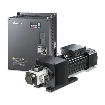
- Page 2 Preface Thank you for choosing the Hybrid Energy System (HES) designed exclusively for the Delta Injection Machine, which consists of Hybrid Servo Controller (VFD-VJ) series and servo oil pump. These production instructions provide the users with complete information regarding the installation, parameter configuration, anomaly diagnosis, troubleshooting, and routine maintenance of the Hybrid Servo Driver.
- Page 3 The figures in the manual are made for illustration purposes and will be slightly different from the actual products. However, the discrepancy will not affect the interests of clients. Since our products are being constantly improved, for information about any changes in specifications, please contact our local agents or visit ( http://www.delta.com.tw/industrialautomation/ ) to download the most recent versions.
-
Page 4: Table Of Contents
Table of Contents Chapter 1 Use and Installation 1-1 Exterior of Product ........................ 1-2 1-2 Specifications........................1-3 1-3 Introduction of Hybrid Energy System................... 1-5 1-4 Installation ..........................1-6 Chapter 2 Wiring 2-1 Wiring ........................... 2-2 2-2 Wiring of Servo oil Pump ...................... 2-4 2-3 Descriptions of Main Loop Terminals .................. - Page 5 Chapter 6 Maintenance Regular Maintenance ........................6-2 Appendix A. Instructions of Product Packaging A-1 Descriptions of Product Packaging ..................A-2 A-2 Detailed List of Product Packaging ..................A-3 Appendix B Optional Accessories B-1 Non-fuse Circuit Breaker...................... B-2 B-2 Reactor..........................B-3 B-3 Digital Keypad KPV-CE01....................
-
Page 6: Chapter 1 Use And Installation
Chapter 1 Use and Installation|HES Series Chapter 1 Use and Installation 1-1 Exterior of Product 1-2 Product Specifications 1-3 Introduction of Hybrid Energy System 1-4 Product Installation Upon receipt of the product, the clients are advised to keep the product in its original packaging box. If... -
Page 7: Exterior Of Product
Chapter 1 Use and Installation|HES Series 1-1 Exterior of Product All Hybrid Energy System has passed strict quality control before being shipped out from the factory, with enforced packaging that sustains impacts. Upon opening the packaging of the Hybrid Energy System, the customers are recommended to conduct the examination by the following steps: Check if there is any damage to Hybrid Energy System during shipping. -
Page 8: Specifications
Chapter 1 Use and Installation|HES Series 1-2 Specifications 230V Series Specifications HES____23A Model Number 063H 080G 080H 100G 100H 100Z 125G 125H 160G 160H 200G Oil Pump Capacity cc/rev Flow Rate L/min Linear Below 1% F.S. Magnetic Hysteresis Below 1% F.S. - Page 9 Chapter 1 Use and Installation|HES Series 460V Series Specifications HES____43A Model Number 063G 063H 080G 080H 100G 100H 100Z 125G 125H 160G 160H 200G Oil Pump Capacity cc/rev Flow Rate L/min Linear Below 1% F.S. Magnetic Below 1% F.S. Hysteresis...
-
Page 10: Introduction Of Hybrid Energy System
Chapter 1 Use and Installation|HES Series 1-3 Introduction of Hybrid Energy System Pressure Command Delta Hybrid (0~10V) Injector Servo Pressure Controller Controller Sensor Flow Rate Command (0~10V) PG Card U V W Over heat protection switch Power Terminal Brake resistance/... -
Page 11: Installation
Chapter 1 Use and Installation|HES Series 1-4 Installation Servo Oil Pump Please install the servo oil pump in an environment with the following conditions to ensure safe product operation: Conditions of Operation Environment Temperature 0°C~ 40°C Environment Relative Humidity 20%~90%, No condensation Oil Temperature 0°C~ 60°C (15°C~ 50°C is recommended) - Page 12 Chapter 1 Use and Installation|HES Series Pipelines & Connections Remove all protection caps on the pump Choose suitable oil tube and connectors (Maximum intake flow rate 1m/s) Recommended Specifications of intake oil tube Flow Rate(L/min) Tube Diameter (inch) Length (m) Above 1.5...
- Page 13 Chapter 1 Use and Installation|HES Series mm (inch) mm (inch) 7.5-20HP 75 (3) 175 (7) 25-75HP 75 (3) 200 (8) 100HP 75 (3) 250 (10) The Hybrid Servo Controller must be installed vertically with screws to sturdy structures. Do not install it upside down, tilted, or horizontally.
-
Page 14: Chapter 2 Wiring
Chapter 2 Wiring|HES Series Chapter 2 Wiring 2-1 Wiring 2-2 Wiring of Servo Oil Pump 2-3 Descriptions of Main circuit Terminals 2-4 Descriptions of Control Loop Terminals Upon opening the top cover of the Hybrid Servo Controller and reveal the wiring terminal bus, check if the terminals of each Main circuit circuit and control loop circuit are labeled clearly. - Page 15 Chapter 2 Wiring|HES Series 2-1 Wiring The wiring of the hybrid energy system consists of that for the servo oil pump and that for the Hybrid Servo Controller. The user must follow the wiring loop below for all wire connections.
- Page 16 Chapter 2 Wiring|HES Series HES125H23A~HES200G23A; HES160H43A~HES200G43A; Brake Brake Unit Resistor VFDB Controller +2/B1 Output terminal 220V 註 * Unused input terminal Start Oil Pump Correct Wiring Method Reset If wiring is conducted before setting parameters, error message will be displayed...
- Page 17 Chapter 2 Wiring|HES Series HES250M43C Note 1* The RB, RC wiring of the braking unit: the overheat protection wiring of the braking unit.
- Page 18 Chapter 2 Wiring|HES Series Note 2* For models with power rating below 22kW For models with power rating below 30kW (including 22kW) (including 30kW) (it is recommended to wrap the output wire around the zero-phase reactor for over three times before connecting it to the motor)
- Page 19 Chapter 2 Wiring|HES Series Multi-pump Operation Mode Confluence Mode M a s te r 1 S la ve (0 3 -1 3 =1 ) (0 3 -1 3 =2 o r 3 ) Pressure Pressure Feedback Command Combine Command Hydraulic Pump...
- Page 20 Chapter 2 Wiring|HES Series When the signals are Confluence , the communication will be a short circuit Div ersio n When the signals are , the communication becomes an open circuit. Pressure SG+ SG- SG+ SG- SG+ SG- SG+ SG-...
-
Page 21: Wiring Of Servo Oil Pump
Chapter 2 Wiring|HES Series 2-2 Wiring of Servo oil Pump Electric Box Delta Hydraulic Servo Motor Corresponding to Controller PG Card Hydraulic Servo Motor Controller U V W (Crimp Terminal Temperature Rise Specification as Protection Switch shown in Figure 2) - Page 22 Chapter 2 Wiring|HES Series External Wiring of Hybrid Servo Controller Power Supply Power Please follow the power rating listed in the Supply user's manual (chapter 1) A larger current may be generated when the Fuse/NFB Fuse/NFB power is turned on. Please refer to Appendix (Optional) B-1 to select suitable non-fused switch or fuse.
-
Page 23: Main Circuit
Chapter 2 Wiring|HES Series 2-3 Main Circuit Terminal Label Description R/L1, S/L2, T/L3 AC line input terminals U/T1, V/T2, W/T3 Output of Hybrid Servo Controller, connected to hybrid servo motor For power improvement of the connection terminal of DC reactor. Please... - Page 24 Chapter 2 Wiring|HES Series Grounding terminals Excellen t Grounding terminals good Grounding terminals Not allowed Mains power terminals (R/L1, S/L2, T/L3): Connect these terminals (R/L1, S/L2, T/L3) via a non-fuse breaker or earth leakage breaker to 3-phase AC power (some models to 1-phase AC power) for circuit protection.
- Page 25 Chapter 2 Wiring|HES Series Terminals [+1, +2] for connecting DC reactor, terminals [+1, +2/B1] for connecting brake resistor: These terminals are used to improve the power factor of DC reactor. There are shorting plates on them when they leave the factory. Remove the shorting plates before connecting the DC reactor.
-
Page 26: Main Circuit Terminals
Chapter 2 Wiring|HES Series Main Circuit Terminals tightening torque on Model No. Wiring crimp type terminal the drive's terminal HES063H23A Ring lug Ring lug 4AWG 30kgf-cm (21mm (26 lbf-in) HES080G23A Heat Shrink Tube WIRE 4AWG HES080H23A (21mm 4AWG HES100G23A (21mm... -
Page 27: Control Terminals
Chapter 2 Wiring|HES Series 2-4 Control Terminals Description of SINK(NPN)/SOURCE(PNP)Mode Switching Terminal Sink m ode Source mode With internal power (+24Vdc) With internal power (+24Vdc) SO N SO N R ES R ES +2 4 V +2 4 V C O M... - Page 28 Chapter 2 Wiring|HES Series Factory Setting (NPN mode) Terminal Function Between terminals SON-DCM: conducting (ON) ; run: open Run-Stop circuit (OFF), Stop Abnormal input from outside Abnormal input from outside Reset reset No function is set for default setting Multiple Function Input: Option 3...
- Page 29 Chapter 2 Wiring|HES Series Factory Setting (NPN mode) Terminal Function Analog Voltage AUI circuit +10V Impedance:11.3kΩ Resolution:12 bits Range:-10~+10VDC -10V Internal Circuit Impedance:16.9kΩ (voltage output) Output Current: 20mA max Resolution: 0~10V corresponds to maximum operation frequency Range: 0~10V Function Setting: Pr.00-05...
-
Page 30: Chapter 3 Start Up
Chapter 3 Flow of machine Adjustment|HES Series Chapter 3 Start Up 3-1 Description of Control Panel 3-2 Adjustment Flow Chart 3-3 Explanations for the Adjustment Steps Please verify again before operation that the wiring is done correctly, especially that the output terminals U/T1, V/T2, and W/T3 of the Hybrid Servo Controller cannot have any power input. -
Page 31: Description Of Control Panel
Chapter 3 Flow of machine Adjustment|HES Series 3-1 Description of Control Panel Description of the Digital Keypad KPVJ-LE01 Run key start AC drive operation Stop/Reset key Stop driver operation and reset in case of anomaly Status Display Display the driver’s cur rent status. -
Page 32: How To Operate The Digital Keypad
Chapter 3 Flow of machine Adjustment|HES Series Display Message Descriptions External Fault. Display “End” for approximately 1 second if input has been accepted by pressing key. After a parameter value has been set, the new value is automatically stored in memory. To modify an entry, use the keys. - Page 33 Chapter 3 Flow of machine Adjustment|HES Series Reference Table for the 7-segment LED Display of the Digital Keypad Number Seven Segment Display English letter Seven Segment - - - - Display English letter Seven Segment - - Display English letter Seven Segment -...
-
Page 34: Adjustment Flow Chart
Chapter 3 Flow of machine Adjustment|HES Series 3-2 Adjustment Flow Chart Set the Hybrid servo motor code Check if the pressure Troubleshoot feedback signal is normal Y E S Calibrate pressure and flow commands Execute venting Adjust Injection /Hold up Complete *The firmware version is 2.04 and above, just proceeds the process to set up HES ID code. -
Page 35: Explanations For The Adjustment Steps
Chapter 3 Flow of machine Adjustment|HES Series 3-3 Explanations for the Adjustment Steps Operate the following steps with the digital operator (KPVJ-LE01/ KPV-CE01) Prior to starting running, please verify again if the wiring is correct, especially that the output terminals U/T1, V/T2, and W/T3 of the Hybrid Servo Controller must correspond to the U, V, and W terminals of the Hybrid servo motor, respectively. - Page 36 Chapter 3 Flow of machine Adjustment|HES Series Step 2. Entry HES ID code* Do not connect the external terminals SON-COM and EMG-COM for the time being. Restore the factory default values by setting the Parameter 00-02 = 10 Parameter reset Pr.
- Page 37 Chapter 3 Flow of machine Adjustment|HES Series Step 3.Check Pressure Feedback Signal Firs, set input voltage Pr. 00-04 = 11 PO Selection of Display Mode Pr. 00-04 11: Display the signal of PO analog input terminal, with 0~10V corresponding to 0~100%.
- Page 38 Chapter 3 Flow of machine Adjustment|HES Series displayed on the operation panel and set it to 00-15. With the controller setting at the lowest pressure, observe the associated value displayed on the operation panel and set it to 00-16. Example: 10V on the pressure sensor corresponds to 250bar.
- Page 39 Chapter 3 Flow of machine Adjustment|HES Series Step 6. Bleed the circuit and make sure if there is any plastic material in the barrel. The machine can start operation only when there are no plastic materials inside the barrel. For low-pressure and low-speed conditions (within 30% of the rated values), use the “manual operation”...
- Page 40 Chapter 3 Flow of machine Adjustment|HES Series power supply is grounded, disconnect the ground wire. If the motor or the three-phase power supply is not grounded, add the ground wire for interference protection. The other possibility is the ground issue of the shielding mesh (as illustrated by the bold red lines in the figure below).
- Page 41 Chapter 3 Flow of machine Adjustment|HES Series Confluence Machine Tuning Procedure Follow the associated descriptions in Chapter 2 to lay out the wiring. Follow steps 1 and 2 described above to enter the electrical codes for the master/slave machines. Then proceed with the steps below.
- Page 42 Chapter 3 Flow of machine Adjustment|HES Series For firmware version 2.03 and above, set the Parameter 01-01=2 Source of operation command Setting value 0: Operation by using the digital keypad of Pr. 01-01 1: Operation by using the external terminals. The Stop button on the keypad is disabled.
- Page 43 Chapter 3 Flow of machine Adjustment|HES Series Shut off the power and the re-supply power for the Slave, and then set the Slave in the speed control mode Speed Control Mode Setting value 0: Speed control of Pr. 00-09 1: Pressure control In this case, the Master can be tuned according to the Step 3 –...
-
Page 44: Chapter 4 Parameter Functions
|HES Series Chapter 4 Parameter Functions Chapter 4 Parameters 4-1 Summary of Parameter Settings 4-2 Detailed Description of Parameters... -
Page 45: Summary Of Parameter Settings
|HES Series Chapter 4 Parameter Functions 4-1 Summary of Parameter Settings 00 System Parameters the parameter can be set during operation Parameter Default Function of the parameter Settings code value 12:230V, 7.5HP 13:460 V, 7.5HP 14:230V, 10HP 15:460V, 10HP 16:230V, 15HP 17:460V, 15HP... - Page 46 |HES Series Chapter 4 Parameter Functions Parameter Default Function of the parameter Settings code value Analog output function 00-05 ○ ○ ○ 0: Output frequency (Hz) selection 1: Frequency command (Hz) ○ ○ ○ ○ ○ ○ 2: Motor speed (Hz) ○...
- Page 47 |HES Series Chapter 4 Parameter Functions Parameter Default Function of the parameter Settings code value Ramp down rate of flow 00-32 ○ ○ ○ 0~1000 ms command 00-33 Valve opening delay time 0~200 ms ○ ○ ○ 00-34 Reserved Over-pressure detection 00-35 ○...
-
Page 48: Motor Parameters
|HES Series Chapter 4 Parameter Functions 01 Motor Parameters the parameter can be set during operation Parameter Default Function of the parameter Settings code value 0: VF 1: Reserved 2: Reserved 01-00 ○ ○ ○ Control mode 3: FOCPG 4: Reserved... - Page 49 (Lq) of the synchronous 0.00.0~655.35mH motor Back EMF of the 01-25 ○ 0~65535 V/krpm synchronous motor 0: ABZ 1: ABZ+HALL (only used for Delta’s servo motors) 01-26 Encode type ○ 2: ABZ+HALL 3: Resolver PG Offset angle of 01-27 ○...
- Page 50 |HES Series Chapter 4 Parameter Functions Parameter Default Function of the parameter Settings code value 0: When the driver runs forward, the motor rotates counterclockwise. When the driver runs reverse, the motor Change rotation rotates clockwise. 01-36 ○ ○ ○...
- Page 51 |HES Series Chapter 4 Parameter Functions 02 Parameters for Protection the parameter can be set during operation Parameter Function of the Default Settings code parameter value 230V series: 350.0~450.0Vdc 380.0 02-00 Software brake level ○ ○ ○ 760.0 460V series: 700.0~900.0Vdc...
- Page 52 |HES Series Chapter 4 Parameter Functions Parameter Function of the Default Settings code parameter value ○ ○ 45: PG slip error (PGF4) 46: Reserved ○ ○ ○ ○ ○ ○ 47: Reserved 48: Reserved ○ ○ ○ 49: External fault input (EF) 50: Emergency stop (EF1) ○...
- Page 53 |HES Series Chapter 4 Parameter Functions 03 Digital/Analog Input/Output Parameters the parameter can be set during operation Parameter Default Function of the parameter Settings code value Multi-function input 0: No function 03-00 ○ ○ ○ command 3 (MI3) 44: Injection signal input...
- Page 54 |HES Series Chapter 4 Parameter Functions 4-11...
-
Page 55: Detailed Description Of Parameters
|HES Series Chapter 4 Parameter Functions 4-2 Detailed Description of Parameters 00 System Parameters the parameter can be set during o peration Hybrid Servo Controller model code ID Control mode FOCPG FOCPM Factory default: Read only Settings Read only Display of rated current of the Hybrid Servo Controller... - Page 56 |HES Series Chapter 4 Parameter Functions 8: Display the estimated output torque (%) (t 0.0: positive torque; - 0.0: negative torque) (%) 9: Display the PG feedback (G) 10: Reserved 11: Display the signal value of the analog input terminal PO...
- Page 57 |HES Series Chapter 4 Parameter Functions Display the speed (rpm) defined by the user Control mode FOCPG FOCPM Factory default: 0 Settings 0~39999 rpm Set the maximum speed of the motor corresponding to the 100% flow. Maximum value for the pressure command...
- Page 58 |HES Series Chapter 4 Parameter Functions To set these parameters, it is necessary to set Parameter 00-09 as 1 Parameter 00-04 = 12 for PI input voltage Send the maximum pressure command through the controller and then check the multi-function display page to enter this value into 00-14...
- Page 59 |HES Series Chapter 4 Parameter Functions Pressure Pressure Feedback P3, I3 P2, I2 00-26 Pressure Command P2, I2 00-26 P1, I1 Time Adjust the Kp value to a proper level first, and then adjust the Ki value (time). If the pressure has overshoot, adjust the kd value.
- Page 60 |HES Series Chapter 4 Parameter Functions Ramp up rate of pressure command Control mode FOCPG FOCPM Factory default: 0 Settings 0~1000ms Ramp down rate of pressure command FOCPG FOCPM Control mode Factory default: 100 Settings 0~1000ms Ramp the pressure value for the pressure command so as to reduce the vibration of the machine.
- Page 61 |HES Series Chapter 4 Parameter Functions Reserved Over-pressure detection level FOCPG FOCPM Control mode Factory default: 230 Settings 0~400 Bar When the pressure feedback exceeds this parameter setting, an “ovP over pressure” error message may occur. Firmware version 2.04 and above, maximum value 400Bar, the previous version’s maximum allowed value is 250Bar.
- Page 62 |HES Series Chapter 4 Parameter Functions Reserved Reserved Percentage of the maximum flow FOCPG FOCPM Control mode Factory default : 100 Settings 0~100% Set up this parameter to adjust the maximum rotation frequency (maximum flow rate). It is not necessary to stop the motor drive to set up this parameter. When this parameter is set to be 100%, it corresponds to the maximum rotation frequency of Pr01-02.
- Page 63 |HES Series Chapter 4 Parameter Functions Pressure Command Rising/ Descending S1 curve Control mode FOCPG FOCPM Factory default : 0 Settings 0~1000ms Pressure Command Rising/ Descending S2 Curve FOCPG FOCPM Control mode Factory default : 0 Settings 0~1000ms To increase the smoothness at start or stop while increasing or decreasing the percentage of the pressure command.
-
Page 64: Control Mode
|HES Series Chapter 4 Parameter Functions 01 Motor Parameters the parameter can be set during operation Control mode FOCPG FOCPM Control mode Factory default: 5 0:V/F 1: Reserved 2: Reserved Settings 3: FOCPG 4: Reserved 5: FOCPM 6: Reserved This parameter determines the control mode of this AC motor. - Page 65 |HES Series Chapter 4 Parameter Functions Acceleration time setting Control mode FOCPG FOCPM Factory default: 0.00 Settings 0.00~600.00 seconds Deceleration time setting FOCPG FOCPM Control mode Factory default: 0.00 Settings 0.00~600.00 seconds The acceleration time determines the time required for the Hybrid servo motor to accelerate from 0.0Hz to [the motor’s maximum frequency] (01-02).
- Page 66 |HES Series Chapter 4 Parameter Functions Equivalent circuit of the motor Pr .01-16 Pr. 01-13 Pr. 01-14 Pr.01-15 Motor equivalent circuit used by VJ NOTE * When the static tuning (parameters 01-07 = 2) is used, you must enter the no-load current ot the motor. It is generally 20 to 50% of the rated current.
- Page 67 |HES Series Chapter 4 Parameter Functions Rated current of the induction motor (A) Unit: Ampere FOCPG Control mode Factory default: #.## Settings 40~120% of the rated driving current To set this parameter, the user can set the rated motor current range shown on the motor’s nameplate.
- Page 68 Enter the back EMF of the synchronous motor. Encoder type selection Control mode FOCPM Factory default: 3 Settings 0: ABZ 1: ABZ+HALL (only used for Delta’s servo motors) 2: ABZ+HALL 3: Resolver Look up table for Encoders & PG cards Parameter Setting Encoder Type Applicable PG Card...
-
Page 69: System Control
|HES Series Chapter 4 Parameter Functions PG Offset angle of synchronous motor Control mode FOCPM Factory default: 0.0 Settings 0.0~360.0° Offset angle of the PG origin for the synchronous motor. Number of poles of the resolver FOCPM Control mode Factory default: 1... - Page 70 Settings 0 : No function 16: Delta’s Hybrid servo motor ECMA-ER181BP3 (11kW220V) 17: Delta’s Hybrid servo motor ECMA- KR181BP3 (11kW380V) 18: Delta’s Hybrid servo motor ECMA-ER221FPS (15kW220V) 19: Delta’s Hybrid servo motor ECMA-KR221FPS (15kW380V) 20: Delta’s Hybrid servo motor ECMA-ER222APS (20kW220V) 21: Delta’s Hybrid servo motor ECMA-KR222APS (20kW380V)
- Page 71 |HES Series Chapter 4 Parameter Functions HES ID# Control mode FOCPG FOCPM Factory default: 0 Settings 0 : No function Example: HES100G23A Model Model HES063H23A 2120 HES063G43A 2040 HES080G23A 3020 HES063H43A 2140 HES080H23A 3120 HES080G43A 3040 HES100G23A 4020 HES080H43A 3140...
- Page 72 |HES Series Chapter 4 Parameter Functions 02 Parameters for Protection the parameter can be set during operation Software brake level Factory default: 380.0/760.0 FOCPG FOCPM Control mode Settings 230V series: 350.0~450.0Vdc 460V series: 700.0~900.0Vdc Sets the reference point of software brake. The reference value is the DC bus voltage.
- Page 73 |HES Series Chapter 4 Parameter Functions 41: Reserved ○ ○ ○ 42: PG feedback error (PGF1) ○ ○ 43: PG feedback loss (PGF2) ○ ○ 44: PG feedback stall (PGF3) ○ ○ 45: PG feedback slip (PGF4) ○ ○ 46: Reserved ○...
- Page 74 |HES Series Chapter 4 Parameter Functions This parameter defines the maximum value of the analog input for 100% of the activation level of the PTC. PTC detection filtering time Control mode FOCPG FOCPM Factory default: 0.20 Settings 0.00 – 10.00 seconds...
- Page 75 |HES Series Chapter 4 Parameter Functions 03 Digital/Analog Input/Output Parameters the parameter can be set during operation Multi-function input command 3 (MI3) Multi-function input command 4 (MI4) Multi-function input command 5 (MI5) Control mode FOCPG FOCPM Factory default: 0 Settings...
- Page 76 |HES Series Chapter 4 Parameter Functions Multi-function output direction Control mode FOCPG FOCPM Factory default: 0 Settings 0~65535 This parameter is used for bit-wise setting. If the corresponding bit is 1, the multi-function output is set as reverse direction. Low-pass filtering time of keypad display...
- Page 77 |HES Series Chapter 4 Parameter Functions Slave's proportion of the Master’s flow Control mode FOCPG FOCPM Factory default: 100.0 Settings 0.0~65535.5 % This parameter setting is required only for the Master but not needed for the Slave. In a confluence system, this parameter value defines the Slave’s portion of the Master’s flow.
- Page 78 |HES Series Chapter 4 Parameter Functions Start-up display selection Control mode FOCPG FOCPM Factory default: 0 Settings 0: F (frequency command) 1: H (actual frequency) 2: Multi-function display (user-defined 00-04) 3: A (Output current) This parameter is used to set the contents of the start-up screen. The content of the user-defined option is displayed in accordance with the setting value of Parameter 00-04.
-
Page 79: Chapter 5 Methods Of Anomaly Diagnosis
|HES Series Chapter 5 Methods of Anomaly Diagnosis Chapter 5 Methods of Anomaly Diagnosis 5-1 Unusual Signal 5-1-1 Indicator Display 5-1-2 Error Messages Displayed on Digital Operation Panel KPVJ-LE01 5-2 Over current (OC) 5-3 Ground fault (GFF) 5-4 Over voltage (OV) -
Page 80: Unusual Signal
|HES Series Chapter 5 Methods of Anomaly Diagnosis 5-1 Unusual Signal 5-1-1 Indicator Display In d ic a to r o f P G c a rd p o we r P o we r in d ic a to r... - Page 81 |HES Series Chapter 5 Methods of Anomaly Diagnosis 5-1-2 Error Messages Displayed on Digital Operation Panel KPVJ-LE01 Display Code Description of Anomaly Troubleshooting Check if the insulation of the wire from U-V-W Over current occurs to the hybrid servo motor is bad acceleration;...
- Page 82 |HES Series Chapter 5 Methods of Anomaly Diagnosis Display Code Description of Anomaly Troubleshooting Ground wire protection, applies when Hybrid Servo Controller Check the wire of hybrid servo motor is detects the output is grounded and shorted or grounded the ground current is higher than Check if IGBT power module is damaged its rated value by over 50%.
-
Page 83: Alarm Reset
|HES Series Chapter 5 Methods of Anomaly Diagnosis Display Code Description of Anomaly Troubleshooting Abnormal in OH1 hardware wire Send back to manufacturer for repair Abnormal in OH2 hardware wire Send back to manufacturer for repair Abnormal cc protection hardware... - Page 84 |HES Series Chapter 5 Methods of Anomaly Diagnosis KPV-CE01 EXT PU STOP RESET...
-
Page 85: Over Current (Oc)
|HES Series Chapter 5 Methods of Anomaly Diagnosis 5-2 Over Current (OC) over current over current in Over current in while running at deceleration acceleration constant speed Remove short circuit Check for any shorts between Troubleshoot or ground fault motor connection terminals U,... -
Page 86: Over Voltage (Ov)
If Lv occurs when the circuit If the capacity of power supply breaker and electromagnetic transformer is appropriate contactor are ON It's likely hybrid servo controller breaks down or malfunctions due to noise. Please contact Delta for assistance. -
Page 87: Overheat (Oh1)
Heat sink is overheated Temperature detection circuit on Is the temperature of heat sink circuit board malfunctions. Please higher than 90°C contact Delta for assistance. Is load too heavy Reduce load Is cooling fan running Replace cooling fan Remove the clog... -
Page 88: Phase Loss (Phl)
Tighten all screws plate tightened Please check wiring and Is voltage of the three phase power system for power supply unbalanced abnormal behavior It's likely hybrid servo controller breaks down or malfunctions due to noise. Please contact Delta for assistance. 5-10... - Page 89 |HES Series Chapter 5 Methods of Anomaly Diagnosis 5-9 Electromagnetic/Induction Noise If there exist noise sources around Hybrid Servo Controller, they will affect Hybrid Servo Controller through radiation or the power lines, leading to malfunction of control loop and causing tripping or even damage of Hybrid Servo Controller.
-
Page 90: Environment And Facilities For Installation
|HES Series Chapter 5 Methods of Anomaly Diagnosis 5-10 Environment and Facilities for Installation The Hybrid Servo Controller is a device for electronic components. Detailed descriptions of the environment suitable for its operation can be found in the specifications. If the listed regulations cannot be followed for any reason, there must be corresponding remedial measures or contingency solutions. -
Page 91: Chapter 6 Maintenance
Chapter 6 Maintenance|HES Series Chapter 6 Maintenance Maintenance and Inspections The Hybrid Servo Controller has a comprehensive fault diagnostic system that includes several different alarms and fault messages. Once a fault is detected, the corresponding protective functions will be activated. The following faults are displayed as shown on the Hybrid Servo Controller digital keypad display. -
Page 92: Maintenance And Inspections
Chapter 6 Maintenance|HES Series Maintenance and Inspections Before the check-up, always turn off the AC input power and remove the cover. Wait at least 10 minutes after all display lamps have gone out, and then confirm that the capacitors have fully discharged by measuring the voltage between DC+ and DC-. - Page 93 Chapter 6 Maintenance|HES Series Mechanical parts Period of inspection Check Items Methods and Criterion Daily Half year Year Visual and aural ○ If there is any abnormal sound or vibration inspection If there are any loose screws Tighten the screws ○...
- Page 94 Chapter 6 Maintenance|HES Series multimeter Main Circuit ~Transformer & Reactor Period of inspection Check Items Method of Inspection Daily Half year Year Any unusual vibration and odor? Visual inspection and ○ listening Main Circuit ~Electromagnetic Contactor & Relay Period of inspection...
-
Page 95: Appendix A. Instructions Of Product Packaging
Appendix A. Instructions of Product Packaging|HES Series Appendix A. Instructions of Product Packaging A-1 Descriptions of Product packaging A-2 Detailed List of Product Packaging This product is made by a manufacturing process with strict quality control. If the product is damaged in the delivery by external force or crushing, please contact... - Page 96 Appendix A. Instructions of Product Packaging|HES Series A-1 Descriptions of Product Packaging Remove the packaging of the external box Models: Models: HES063H23A; HES080G23A; HES080H23A; HES125G23A; HES125G43A; HES100G23A; HES100H23A; HES063G43A;HES063H43A; HES080G43A; HES080H43A; HES100G43A; HES100H43A; Models: HES125H23A; HES160G23A; HES125H43A; HES160G43A; HES160H43A; HES200G43A...
-
Page 97: Detailed List Of Product Packaging
Appendix A. Instructions of Product Packaging|HES Series A-2 Detailed List of Product Packaging HES063H23A 1 Servo controller VFD110VL23A06HA Unit: mm[inch] Frame 235.0 [9.25] 204.0 [8.03] 350.0 [13.78] 337.0 [13.27] 146.0 [5.75] 6.5 [0.26] 2 Servo oil pump HSP-025-110-23A Component Model Number... - Page 98 Appendix A. Instructions of Product Packaging|HES Series 3 Accessories Kit HESP-063-H-N-23 Component Model Number Quantity PG card EMVJ-PG02R ※ Braking resistor BR1K0W8P3 Coding device cable 5m Magnetic ring of power cable Sensor clamp ※ Braking resistor 1000W 8.3Ω Unit: min...
- Page 99 Appendix A. Instructions of Product Packaging|HES Series HES080G23A 1 Servo controller VFD110VL23A08GA Unit: mm[inch] Frame 235.0 [9.25] 204.0 [8.03] 350.0 [13.78] 337.0 [13.27] 146.0 [5.75] 6.5 [0.26] 2 Servo oil pump HSP-032-110-23A Component Model Number Quantity Motor ECMA-ER181BP3 Oil pump...
- Page 100 Appendix A. Instructions of Product Packaging|HES Series 3 Accessories Kit HESP-080-G-N-23 Component Model Number Quantity PG card EMVJ-PG02R BR1K0W8P3 ※ Braking resistor Coding device cable 5m Magnetic ring of power cable Sensor clamp ※ Braking resistor 1000W 8.3Ω Unit: min...
- Page 101 Appendix A. Instructions of Product Packaging|HES Series HES080H23A 1 Servo controller VFD150VL23A08HA Unit: mm[inch] Frame 255.0 [10.04] 226.0 [8.90] 403.8 [15.90] 384.0 [15.12] 168.0 [6.61] 8.5 [0.33] 2 Servo oil pump HSP-032-110-23A Component Model Number Quantity Motor ECMA-ER181BP3 Oil pump...
- Page 102 Appendix A. Instructions of Product Packaging|HES Series 3 Accessories Kit HESP-080-H-N-23 Component Model Number Quantity PG card EMVJ-PG02R BR1K0W5P8 ※ Braking resistor Coding device cable 5m Magnetic ring of power cable Sensor clamp ※ Braking resistor 1000W 5.8Ω Unit: min...
- Page 103 Appendix A. Instructions of Product Packaging|HES Series HES100G23A 1 Servo controller VFD150VL23A10GA Unit: mm[inch] Frame 255.0 [10.04] 226.0 [8.90] 403.8 [15.90] 384.0 [15.12] 168.0 [6.61] 8.5 [0.33] 2 Servo oil pump HSP-040-110-23A Component Model Number Quantity Motor ECMA-ER181BP3 Oil pump...
- Page 104 Appendix A. Instructions of Product Packaging|HES Series 3 Accessories Kit HESP-100-G-N-23 Component Model Number Quantity PG card EMVJ-PG02R BR1K0W5P8 ※ Braking resistor Coding device cable 5m Magnetic ring of power cable Sensor clamp ※ Braking resistor 1000W 5.8Ω Unit: min...
- Page 105 Appendix A. Instructions of Product Packaging|HES Series HES100H23A 1 Servo controller VFD185VL23A10HA Unit: mm[inch] Frame 255.0 [10.04] 226.0 [8.90] 403.8 [15.90] 384.0 [15.12] 168.0 [6.61] 8.5 [0.33] 2 Servo oil pump HSP-040-110-23A Component Model Number Quantity Motor ECMA-ER181BP3 Oil pump...
- Page 106 Appendix A. Instructions of Product Packaging|HES Series Component Model Number Quantity PG card EMVJ-PG02R BR1K0W5P8 ※ Braking resistor Coding device cable 5m Magnetic ring of power cable Sensor clamp ※ Braking resistor 1000W 5.8Ω Unit: min A-12...
- Page 107 Appendix A. Instructions of Product Packaging|HES Series HES100Z23A 1 Servo controller VFD220VL23A10ZA Unit: mm[inch] Frame 255.0 [10.04] 226.0 [8.90] 403.8 [15.90] 384.0 [15.12] 168.0 [6.61] 8.5 [0.33] 2 Servo oil pump HSP-040-150-23A 783.4 433.0 165.0 185.4 1"PT( ) 牙 1-1/4" PT( ) 牙...
- Page 108 Appendix A. Instructions of Product Packaging|HES Series 3 Accessories Kit HESP-100-Z-N-23 Component Model Number Quantity PG card EMVJ-PG02R BR1K0W5P8 ※ Braking resistor Coding device cable 5m Magnetic ring of power cable Sensor clamp ※ Braking resistor 1000W 5.8Ω Unit: min...
- Page 109 Appendix A. Instructions of Product Packaging|HES Series HES125G23A 1 Servo controller VFD220VL23A12GA Unit: mm[inch] Frame 255.0 [10.04] 226.0 [8.90] 403.8 [15.90] 384.0 [15.12] 168.0 [6.61] 8.5 [0.33] 2 Servo oil pump HSP-050-150-23A Component Model Number Quantity Motor ECMA-ER221FPS Oil pump...
- Page 110 Appendix A. Instructions of Product Packaging|HES Series 3 Accessories Kit HESP-125-G-N-23 Component Model Number Quantity PG card EMVJ-PG02R BR1K0W5P8 ※ Braking resistor Coding device cable 5m Magnetic ring of power cable Sensor clamp ※ Braking resistor 1000W 5.8Ω Unit: min...
- Page 111 Appendix A. Instructions of Product Packaging|HES Series HES125H23A 1 Servo controller VFD300VL23A12HA Unit: mm[inch] Frame 370.0 335.0 595.0 589.0 560.0 260.0 132.5 18.0 13.0 13.0 18.0 [14.57] [13.19] [23.43] [23.19] [22.05] [10.24] [5.22] [0.71] [0.51] [0.51] [0.71] 2 Servo oil pump HSP-050-150-23A...
- Page 112 Appendix A. Instructions of Product Packaging|HES Series 3 Accessories Kit HESP-125-H-B-23 Component Model Number Quantity PG card EMVJ-PG02R ※1 Braking unit VFDB-2022 ※2 Braking resistor BR1K0W5P8 Coding device cable Magnetic ring of power Sensor clamp*1 5m*1 cable*3 ※1 Braking unit VFDB-2022 121.0 [4.76]...
- Page 113 Appendix A. Instructions of Product Packaging|HES Series HES160G23A 1 Servo controller VFD300VL23A16GA Unit: mm[inch] Frame 370.0 335.0 595.0 589.0 560.0 260.0 132.5 18.0 13.0 13.0 18.0 [14.57] [13.19] [23.43] [23.19] [22.05] [10.24] [5.22] [0.71] [0.51] [0.51] [0.71] 2 Servo oil pump HSP-064-150-23A...
- Page 114 Appendix A. Instructions of Product Packaging|HES Series 3 Accessories Kit HESP-160-G-B-23 Component Model Number Quantity PG card EMVJ-PG02R ※1 Braking unit VFDB-2022 BR1K0W5P8 ※2 Braking resistor Coding device cable Magnetic ring of power Sensor clamp*1 5m*1 cable*3 ※1 Braking unit VFDB-2022 121.0 [4.76]...
- Page 115 Appendix A. Instructions of Product Packaging|HES Series HES160H23A 1 Servo controller VFD370VL23A16HA Unit: mm[inch] Frame 370.0 335.0 595.0 589.0 560.0 260.0 132.5 18.0 13.0 13.0 18.0 [14.57] [13.19] [23.43] [23.19] [22.05] [10.24] [5.22] [0. 1] [0.51] [0.51] [0.71] 2 Servo oil pump HSP-064-200-23A...
- Page 116 Appendix A. Instructions of Product Packaging|HES Series 3 Accessories Kit HESP-160-H-B-23 Component Model Number Quantity PG card EMVJ-PG02R ※1 Braking unit VFDB-2022 BR1K0W5P8 ※2 Braking resistor Coding device cable Magnetic ring of power Sensor clamp*1 5m*1 cable*3 ※1 Braking unit VFDB-2022 121.0 [4.76]...
- Page 117 Appendix A. Instructions of Product Packaging|HES Series HES200G23A 1 Servo controller VFD370VL23A20GA Unit: mm[inch] Frame 370.0 335.0 595.0 589.0 560.0 260.0 132.5 18.0 13.0 13.0 18.0 [14.57] [13.19] [23.43] [23.19] [22.05] [10.24] [5.22] [0.71] [0.51] [0.51] [0.71] 2 Servo oil pump HSP-200-G-B-23...
- Page 118 Appendix A. Instructions of Product Packaging|HES Series 3 Accessories Kit HESP-200-G-B-23 Component Model Number Quantity PG card EMVJ-PG02R ※1 Braking unit VFDB-2022 BR1K5W5P8 ※2 Braking resistor Coding device cable Magnetic ring of power Sensor clamp*1 5m*1 cable*3 ※1 Braking unit VFDB-2022 121.0 [4.76]...
- Page 119 Appendix A. Instructions of Product Packaging|HES Series HES063G43A 1 Servo controller VFD110VL43A06GA Unit: mm[inch] Frame 235.0 [9.25] 204.0 [8.03] 350.0 [13.78] 337.0 [13.27] 146.0 [5.75] 6.5 [0.26] 2 Servo oil pump HSP-025-110-43A Component Model Number Quantity Motor ECMA-ER181BP3 Oil pump...
- Page 120 Appendix A. Instructions of Product Packaging|HES Series 3 Accessories Kit HESP-063-G-N-43 Component Model Number Quantity PG card EMVJ-PG02R BR1K0W025 ※ Braking resistor Coding device cable 5m Magnetic ring of power cable Sensor clamp ※ Braking resistor 1000W 25Ω Unit: min...
- Page 121 Appendix A. Instructions of Product Packaging|HES Series HES063H43A 1 Servo controller VFD150VL43B06HA Unit: mm[inch] Frame 235.0 [9.25] 204.0 [8.03] 350.0 [13.78] 337.0 [13.27] 146.0 [5.75] 6.5 [0.26] 2 Servo oil pump HSP-025-110-43A Component Model Number Quantity Motor ECMA-ER181BP3 Oil pump...
- Page 122 Appendix A. Instructions of Product Packaging|HES Series 3 Accessories Kit HESP-063-H-N-43 Component Model Number Quantity PG card EMVJ-PG02R BR1K0W025 ※ Braking resistor Coding device cable 5m Magnetic ring of power cable Sensor clamp ※ Braking resistor 1000W 25Ω Unit: min...
- Page 123 Appendix A. Instructions of Product Packaging|HES Series HES080G43A 1 Servo controller VFD150VL43B08GA Unit: mm[inch] Frame 235.0 [9.25] 204.0 [8.03] 350.0 [13.78] 337.0 [13.27] 146.0 [5.75] 6.5 [0.26] 2 Servo oil pump HSP-032-110-43A Component Model Number Quantity Motor ECMA-ER181BP3 Oil pump...
- Page 124 Appendix A. Instructions of Product Packaging|HES Series 3 Accessories Kit HESP-080-G-N-43 Component Model Number Quantity PG card EMVJ-PG02R BR1K0W025 ※ Braking resistor Coding device cable 5m Magnetic ring of power cable Sensor clamp ※ Braking resistor 1000W 25Ω Unit: min...
- Page 125 Appendix A. Instructions of Product Packaging|HES Series HES080H43A 1 Servo controller VFD185VL43B Unit: mm[inch] Frame 235.0 [9.25] 204.0 [8.03] 350.0 [13.78] 337.0 [13.27] 146.0 [5.75] 6.5 [0.26] 2 Servo oil pump HSP-032-110-43A Component Model Number Quantity Motor ECMA-ER181BP3 Oil pump...
- Page 126 Appendix A. Instructions of Product Packaging|HES Series 3 Accessories Kit HESP-080-H-N-43 Component Model Number Quantity PG card EMVJ-PG02R BR1K0W025 ※ Braking resistor Coding device cable 5m Magnetic ring of power cable Sensor clamp ※ Braking resistor 1000W 25Ω Unit: min...
- Page 127 Appendix A. Instructions of Product Packaging|HES Series HES100G43A 1 Servo controller VFD185VL43B10GA Unit: mm[inch] Frame 235.0 [9.25] 204.0 [8.03] 350.0 [13.78] 337.0 [13.27] 146.0 [5.75] 6.5 [0.26] 2 Servo oil pump HSP-040-110-43A Component Model Number Quantity Motor ECMA-ER181BP3 Oil pump...
- Page 128 Appendix A. Instructions of Product Packaging|HES Series 3 Accessories Kit HESP-100-G-N-43 Component Model Number Quantity PG card EMVJ-PG02R BR1K0W025 ※ Braking resistor Coding device cable 5m Magnetic ring of power cable Sensor clamp ※ Braking resistor 1000W 25Ω Unit: min...
- Page 129 Appendix A. Instructions of Product Packaging|HES Series HES100H43A 1 Servo controller VFD220VL43A10HA Unit: mm[inch] Frame 255.0 [10.04] 226.0 [8.90] 403.8 [15.90] 384.0 [15.12] 168.0 [6.61] 8.5 [0.33] 2 Servo oil pump HSP-040-110-43A Component Model Number Quantity Motor ECMA-ER181BP3 Oil pump...
- Page 130 Appendix A. Instructions of Product Packaging|HES Series 3 Accessories Kit HESP-100-H-N-43 Component Model Number Quantity PG card EMVJ-PG02R BR1K0W025 ※ Braking resistor Coding device cable 5m Magnetic ring of power cable Sensor clamp ※ Braking resistor 1000W 25Ω Unit: min...
- Page 131 Appendix A. Instructions of Product Packaging|HES Series HES100Z43A 1 Servo controller VFD220VL43A10ZA Unit: mm[inch] Frame 255.0 [10.04] 226.0 [8.90] 403.8 [15.90] 384.0 [15.12] 168.0 [6.61] 8.5 [0.33] 2 Servo oil pump HSP-040-150-43A 783.4 433.0 165.0 185.4 1"PT( ) 牙 1-1/4" PT( ) 牙...
- Page 132 Appendix A. Instructions of Product Packaging|HES Series 3 Accessories Kit HESP-100-Z-N-43 Component Model Number Quantity PG card EMVJ-PG02R BR1K0W025 ※ Braking resistor Coding device cable 5m Magnetic ring of power cable Sensor clamp ※ Braking resistor 1000W 25Ω Unit: min...
- Page 133 Appendix A. Instructions of Product Packaging|HES Series HES125G43A 1 Servo controller VFD220VL43A12GA Unit: mm[inch] Frame 255.0 [10.04] 226.0 [8.90] 403.8 [15.90] 384.0 [15.12] 168.0 [6.61] 8.5 [0.33] 2 Servo oil pump HSP-050-150-43A Component Model Number Quantity Motor ECMA-KR221FPS Oil pump...
- Page 134 Appendix A. Instructions of Product Packaging|HES Series 3 Accessories Kit HESP-125-G-N-43 Component Model Number Quantity PG card EMVJ-PG02R BR1K0W020 ※ Braking resistor Coding device cable 5m Magnetic ring of power cable Sensor clamp ※ Braking resistor10000W 20Ω Unit: min A-40...
- Page 135 Appendix A. Instructions of Product Packaging|HES Series HES125H43A 1 Servo controller VFD300VL43B12HA Unit: mm[inch] Frame 255.0 [10.04] 226.0 [8.90] 403.8 [15.90] 384.0 [15.12] 168.0 [6.61] 8.5 [0.33] 2 Servo oil pump HSP-050-150-43B Component Model Number Quantity Motor ECMA-KR221FPS Oil pump...
- Page 136 Appendix A. Instructions of Product Packaging|HES Series 3 Accessories Kit HESP-125-H-N-43 Component Model Number Quantity PG card EMVJ-PG02R BR1K0W014 ※ Braking resistor Coding device cable Magnetic ring of power Sensor clamp*1 5m*1 cable*3 ※ Braking resistor 1000W 14Ω Unit: min...
- Page 137 Appendix A. Instructions of Product Packaging|HES Series HES160G43A 1 Servo controller VFD300VL43B16GA Unit: mm[inch] Frame 255.0 [10.04] 226.0 [8.90] 403.8 [15.90] 384.0 [15.12] 168.0 [6.61] 8.5 [0.33] 2 Servo oil pump HSP-064-150-43A Component Model Number Quantity Motor ECMA-KR221FPS Oil pump...
- Page 138 Appendix A. Instructions of Product Packaging|HES Series 3 Accessories Kit HESP-160-G-N-43 Component Model Number Quantity PG card EMVJ-PG02R BR1K0W014 ※Braking resistor Coding device cable Magnetic ring of power Sensor clamp*1 5m*1 cable*3 ※Braking resistor1000W 14Ω Unit: min A-44...
- Page 139 Appendix A. Instructions of Product Packaging|HES Series HES160H43A 1 Servo controller VFD370VL43B16HA Unit: mm[inch] Frame Ø1 Ø2 Ø3 280.0 235.0 516.0 500.0 475.0 442.0 251.7 94.2 16.0 11.0 18.0 62.7 34.0 22.0 [11.02] [9.25] [20.31] [19.69] [18.70] [17.40] [9.91] [3.71] [0.63]...
- Page 140 Appendix A. Instructions of Product Packaging|HES Series 3 Accessories Kit HESP-160-H-B-43 Component Model Number Quantity PG card EMVJ-PG02R ※1 Braking unit VFDB-4045 BR1K5W013 ※2 Braking resistor Coding device cable Magnetic ring of power Sensor clamp*1 5m*1 cable*3 ※1 Braking unit VFDB-4045 121.0 [4.76]...
- Page 141 Appendix A. Instructions of Product Packaging|HES Series HES200G43A 1 Servo controller VFD370VL43B20GA Unit: mm[inch] Frame Ø1 Ø2 Ø3 280.0 235.0 516.0 500.0 475.0 442.0 251.7 94.2 16.0 11.0 18.0 62.7 34.0 22.0 [11.02] [9.25] [20.31] [19.69] [18.70] [17.40] [9.91] [3.71] [0.63]...
- Page 142 Appendix A. Instructions of Product Packaging|HES Series 3 Accessories Kit HESP-200-G-B-43 Component Model Number Quantity PG card EMVJ-PG02R ※1 Braking unit VFDB-4045 BR1K5W013 ※2 Braking resistor Coding device cable Magnetic ring of power Sensor clamp*1 5m*1 cable*3 ※1 Braking unit VFDB-4045 121.0 [4.76]...
-
Page 143: Appendix B Optional Accessories
Appendix B Optional Accessories|HES Series Appendix B Optional Accessories B-1 Non-fuse Circuit Breaker Chart B-2 Reactor B-3 Digital Keypad KPV-CE01 B-4 Communication Card B-5 EMI Filter B-6 Brake Unit This VFD-VL AC motor drive has gone through rigorous quality control tests at the factory before shipment. -
Page 144: B-1 Non-Fuse Circuit Breaker
Appendix B Optional Accessories|HES Series B-1 Non-fuse Circuit Breaker Chart UL certification: Per UL 508, paragraph 45.8.4, part a. The rated current of the breaker shall be within 2 to 4 times rated input current of hybrid servo Controller. Hybrid Servo Controller. -
Page 145: Reactor
Appendix B Optional Accessories|HES Series B-2 Reactor B-2-1 AC Input Reactor Recommended Value 460V, 50/60Hz, 3-phase Inductance(mh) Maximum Fundamental Amps Continuous Amps Impedance Impedance 37.5 52.5 18.5 52.5 67.5 82.5 0.85 0.45 230V, 50/60Hz, 3-phase Inductance(mh) Maximum Fundamental Amps Continuous Amps... - Page 146 Appendix B Optional Accessories|HES Series Applications for AC Reactor Connected in input circuit Application 1 When more than one drive is connected to the same power, one of them is ON during operation. Question When applying to one of the Hybrid Servo Controller, the charge current of capacity may cause voltage ripple.
- Page 147 Appendix B Optional Accessories|HES Series Application 3 Used to improve the input power factor, to reduce harmonics and provide protection from AC line disturbances. (Surges, switching spikes, short interruptions, etc.). AC line reactor should be installed when the power supply capacity is 500kVA or more and exceeds 6 times the inverter capacity, or the mains wiring distance 10m.
- Page 148 Appendix B Optional Accessories|HES Series B-2-2 Zero Phase Reactor RF220X00A UNIT: mm(inch) Recommended Cable Figure A Wire Size (mm Wiring type Qty. Each wire must be wrapped at least three times Method Nominal (Note) AWG mm when it threads the zero phase reactor, with the reactor placed as close to the Hybrid Servo ≤10 ≤5.3...
- Page 149 Appendix B Optional Accessories|HES Series B-2-3 DC Reactor 230V DC Choke Inductance(mh) Input Voltage DC Amps 0.85 0.75 Built-in 230Vac Built-in 50/60Hz 18.5 Built-in 3-Phase Built-in Built-in Built-in 460V DC Choke Inductance(mh) Input Voltage DC Amps 3.75 4.00 Built-in Built-in 460Vac 18.5...
-
Page 150: Digital Keypad Kpv-Ce01
Appendix B Optional Accessories|HES Series B-3 Digital Keypad KPV-CE01 The digital keypad is the display of VFD-VJ series. The following keypad appearance is only for reference and please see the product for actual appearance. Description of the Digital Keypad KPV-CE01... - Page 151 Appendix B Optional Accessories|HES Series How to Operate the Digital Keypad KPV-CE01 Se le ct io n mode START MO DE MO DE MO DE MO DE MO DE GO START PROG NOT E: In the s elect ion mo de, pres s to se t t he p aramet ers.
- Page 152 Appendix B Optional Accessories|HES Series To copy pa ramete rs 1 Copy pa ramete rs f rom t he Drive to the KP V-CE01 MO DE MO DE MO DE MO DE MO DE abo ut 2 -3 s ec onds It will displa y "...
- Page 153 Appendix B Optional Accessories|HES Series Dimension of the Digital Keypad (KPV-CE01) Unit: mm [inch] K P V -C E O 1 R U N S T O P JO G F W D R E V E X T JO G...
-
Page 154: Communication Card
Appendix B Optional Accessories|HES Series B-4 Communication Card EMVJ-MF01 Terminal Description Ground RS485 connection points Common Signal Terminal POWER Power Light When the light is on, it is set as master When the light is on, a message sent from the... -
Page 155: Emi Filter
All electrical equipment, including drives, will generate high-frequency/low-frequency noise and will interfere with peripheral equipment by radiation or conduction when in operation. By using an EMI filter with correct installation, much interference can be eliminated. It is recommended to use DELTA EMI filter to have the best interference elimination performance. - Page 156 Appendix B Optional Accessories|HES Series Protective coating required at contacts between brackets and metal plates to ensure good contact. U-shape metal bracket Metal plate with good grounding Figure 1 Figure 2 The length of motor cable When motor is driven by a drive of PWM type, the motor terminals will experience surge voltages easily due to components conversion of drive and cable capacitance.
-
Page 157: Brake Unit
Appendix B Optional Accessories|HES Series B-6 Brake Unit Individual Parts and Function Explanation Input Voltage Setup Activated Loop Terminal Fault Loop Terminal Brake Resistance Power Input Terminal Terminal +(P) -(N) B1, B2 CHARGE ACT Input Voltage Setup Power Brake Action... - Page 158 Appendix B Optional Accessories|HES Series Terminal Wire Gauge Circuit Terminal Mark Wire Gauge AWG (mm Screw Torque Power Input + (P)、- (N) 18 kgf-cm (15.6 in-lbf) 10~12AWG (3.5~5.5mm Circuit Braking Resistor B1、B2 10~12AWG (3.5~5.5mm 18 kgf-cm (15.6 in-lbf) Output M1、M2 20~18AWG (0.25~0.75mm...
Need help?
Do you have a question about the HES Series and is the answer not in the manual?
Questions and answers