Table of Contents
Advertisement
Quick Links
Advertisement
Table of Contents

Related Manuals for Husqvarna Rider Pro 18 AWD


Summary of Contents for Husqvarna Rider Pro 18 AWD
- Page 1 Workshop manual Rider Pro 18 AWD ProFlex 21 AWD English...
-
Page 3: Table Of Contents
Workshop Manual for the Rider Pro 18 AWD and ProFlex 21 AWD Contents Contents ..............1 Adjusting the Hydrostatic Safety Instructions ..........3 Transmission Cable ......... 46 General Instructions ..........3 Checking and Adjusting the Throttle Cable ..46 Special Instructions ..........3 Checking and Adjusting the Choke Cable ..47 Risk of sparking ..........4... - Page 4 Fuses ..............109 Replacing the Light Bulbs .......110 Safety System ..........111 Hydraulic System ..........113 Hydraulic Hygiene ...........113 Hydraulic Oils ..........113 Fixing Oil Leaks ..........113 Keep the Hydraulic Oil Clean ......114 Working Methods ..........114 Component Locations ........115 Bleeding the Hydraulic System .......116 Power Steering ..........116 Replacing the Lift Cylinder ProFlex ....116 Valve Assembly ProFlex .........117...
-
Page 5: Safety Instructions
SAFETY INSTRUCTIONS Safety Instructions General Instructions No one may repair the rider unless they have read This workshop manual is written for personnel with and understood the content of this workshop general knowledge about the repair and service of manual. riders. -
Page 6: Risk Of Sparking
SAFETY INSTRUCTIONS Risk of sparking Sparking can occur when working with the battery and the thick cables in the starter motor circuit. This can cause the battery to explode, fire or eye injuries. Sparking in the circuit can not occur once the battery's power connection cable (usually the black negative cable) has been disconnected. -
Page 7: Special Tools
SPECIAL TOOLS Special Tools The following special tools are used when working on the rider. Special tools for the engine and transmission are specified in resp. Workshop Manuals. 8009-519 506 66 48-01 Engine belt pulley remover. 506 56 76-01 Allen key 5/16" for loosening the engine belt pulley’s Allen screw (Kawasaki). 506 89 92-01 Counter to aid removing the engine belt pulley. - Page 8 SPECIAL TOOLS 506 56 76-01 8009-518 8009-194 8009-517 8009-515 The figures show how the special tools are used. English-...
-
Page 9: Specifications
SPECIFICATIONS Specifications Rider Pro 18 AWD Rider ProFlex 21 AWD Dimensions and weight Length, base machine 2 030 mm/6.66 ft with tow hook 2 080 mm/6.82 ft with tow hook Length with Combi 112 2 400 mm/7.87 ft with tow hook 2 450 mm/8.04 ft with tow hook... - Page 10 SPECIFICATIONS Rider Pro 18 AWD Rider ProFlex 21 AWD Electrical system Type 12 V, negative grounded 12 V, negative grounded Battery 12 V, 24 Ah 12 V, 24 Ah Main fuse Flat pin, 15 A Flat pin, 15 A Fuse power outlet Flat pin, 7.5 A...
- Page 11 SPECIFICATIONS Cutting Unit Combi 94XP Combi 103 Cutting width 940 mm/37" 1 030 mm/40,5" Cutting heights 30-90 mm/1.19-3.56" 45-95 mm/1.75-3.75" Blade length 360 mm/14" 410 mm/16" Guaranteed noise level 100 dB(A) 100 dB(A) Width 1 050 mm/41.5" 1 115 mm/45.5" Weight 52 kg/115 lb 48 kg/106 lb...
- Page 12 SPECIFICATIONS English-...
-
Page 13: Delivery And Dealer Service
DELIVERY AND DEALER SERVICE Delivery and Dealer Service After the First 8 Hours Delivery Service Change engine oil. Fill the battery with battery acid and charge for four hours. After the first 50 hours Fit the steering wheel, seat and, where applicable, other components. -
Page 14: 300-Hour Service
DELIVERY AND DEALER SERVICE 300-Hour Service At Least Once Each Season Inspect the machine. Come to agreement with Clean the engine’s cooling air intake the customer as to what additional work is to (25 hours). be carried out. Replace the air cleaner’s pre-filter Perform the 25-hour service. -
Page 15: Service Schedule
DELIVERY AND DEALER SERVICE Service Schedule = Described in this workshop manual. The following is a list of maintenance procedures that must be performed on the rider. Most of the ❍ = Not described in this workshop manual points that are not described in this workshop or the operator’s manual. - Page 16 DELIVERY AND DEALER SERVICE Maintenance Page Daily Daily Weekly Maintenance mainte- mainte- mainte- least interval in hours nance nance once a nance before after year 100 300 Clean around all belts, belt pulleys, etc. Lubricate the belt adjuster (nipple) Lubricate the right rear axle bearing (nipple).
- Page 17 DELIVERY AND DEALER SERVICE Maintenance Page Daily Daily Weekly Maintenance mainte- mainte- mainte- least interval in hours nance nance once a nance before after year 100 300 Clean/replace the spark plugs. Change the inline fuel filter. Clean/replace the pulse air filter. ❍...
-
Page 18: Delivery Procedures
DELIVERY AND DEALER SERVICE Delivery Procedures To our dealers In conjunction with the delivery, you shall also give A well performed pre delivery service is the first the customer the information required to handle step towards an active after-sales market. and maintain their machine in a safe manner. - Page 19 DELIVERY AND DEALER SERVICE Packaging and Unpacking Packed Components: The machine is normally packed using special Number Component packaging when delivered from the factory. This 1 pc Steering wheel with steering rod packaging is comprised of a wood base with a strong cardboard top section, all held together with 1 pc Allen screw for steering rod...
-
Page 20: Battery
DELIVERY AND DEALER SERVICE Battery WARNING! Actions with acid contact External: Rinse thoroughly with water. Internal: Drink large quantities of water or milk. Contact a doctor as soon as possible. Eyes: Rinse thoroughly with water. Con- tact a doctor as soon as possible. The battery emits explosive gases. -
Page 21: Steering Wheel
DELIVERY AND DEALER SERVICE Steering Wheel • Fit the steering wheel with the steering rod on the steering column. Choose a suitable height position. • Thread the Allen screw into the thread of the steering column. Work the wheel and tighten the Allen screw so that it reaches the bottom of the thread. -
Page 22: Check The Oil Level In The Hydraulic Tank
DELIVERY AND DEALER SERVICE Check the Oil Level in the Hydraulic Tank Remove the transmission cover. Loosen both screws (one on each side) and lift off the transmission cover. Leave the cover removed for now. 8009-603 Transmission cover Check that there is oil in the hydraulic tank. The oil level should be visible in the sight glass. -
Page 23: Checking And Adjusting The Cutting Unit
DELIVERY AND DEALER SERVICE Checking and Adjusting the Cutting Unit Performed after checking the tyre air pressures. See ”Adjusting the Unit’s Parallelism and Cutting Height” on page 95. Test Running Fill with petrol. The engine should be run on a minimum of 87-octane unleaded petrol (not mixed with oil). -
Page 24: Engine Speed Regulator
DELIVERY AND DEALER SERVICE Check that the cutting unit works and that no unusual sounds are heard. Using the lever, the cutting height can be adjusted in 7 different positions. 8009-327 Cutting height setting Check that the hydraulic cutting unit lift is functioning on the ProFlex 21. -
Page 25: Final Inspection
DELIVERY AND DEALER SERVICE Final Inspection Bleed the hydraulic system of excess air after test running. Check the oil level in the hydraulic tank and top up if necessary. Check that there are no leaks, including engine oil and fuel leaks. Replace the transmission cover. - Page 26 DELIVERY AND DEALER SERVICE English-...
-
Page 27: Design And Function
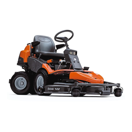
8009-318 Rider ProFlex 21 AWD This publication describes the Husqvarna Rider Husqvarna Riders are a series of large capacity ProFlex 18 AWD from the 2005 model and the riders. They are available in several sizes, ranging ProFlex 21 AWD from the 2005 model. There are from the smallest, the Rider 11, to the largest, the special workshop manuals for older machines. - Page 28 DESIGN AND FUNCTION Rider ProFlex is equipped as standard with cutting unit type Combi 112 or Combi 122 Rider Pro 18 can be supplied with Combi 94, Combi 103 or Combi 112 8009-288 8009-601 Combi 103 Combi 94 8009-290 8009-288 Combi 122 Combi 112 English-...
-
Page 29: Serial Number
DESIGN AND FUNCTION Serial Number The machine’s serial number is found on the printed plate at the front under the seat. Stated on the plate, from the top, are: • The machine’s type designation. • The manufacturer's type number. • The machine’s serial number. -
Page 30: Engine
DESIGN AND FUNCTION Engine The Husqvarna Rider ProFlex series comprises professional machines with twin- cylinder, air-cooled Kawasaki engines. Major engine repairs are not described in this workshop manual. This information can be found in Kawasaki’s manuals, which contain detailed information about adjusting and repairing the engines. -
Page 31: Steering
DESIGN AND FUNCTION Steering A Rider easily cuts around all obstacles on the All mowers in the Rider series have articulated lawn. steering. Pro 18 AWD and ProFlex 21 AWD are equipped with hydraulic servo steering. The A mechanical linkage gives the front wheels a steering force from the steering wheel is higher speed when cornering. -
Page 32: Driving
DESIGN AND FUNCTION Driving The Rider Pro and ProFlex are equipped with a hydrostatic transmission that gives the driver complete control over driving. The speed is controlled using the forward or reverse pedals. The AWD machines are equipped with constantly engaged all wheel drive, which means a differential lock is not required. - Page 33 DESIGN AND FUNCTION The oil is drained using two plugs on the underside. One plug drains the hydraulic motor and the other drains the differential. 8009-631 Oil drainage On the AWD machines pressure is provided to the transmission from an axial piston pump.
-
Page 34: Cutting Unit
DESIGN AND FUNCTION Cutting Unit Rider Pro 18 AWD is supplied with cutting unit The entire Rider series is equipped with a front- Combi 94XP. Combi 103 or Combi 112 can also be mounted cutting unit in order to mow efficiently used. - Page 35 DESIGN AND FUNCTION 8009-687 The cutting unit's lifting device on ProFlex The cutting height is adjusted using the lever that horizontal connecting rod and the tongue of the is attached to the shaft with a joint and a spring. forward perpendicular shaft on the top of the The same shaft holds the adjuster for the cutting cutting unit cover.
- Page 36 DESIGN AND FUNCTION 8009-400 Cutting height adjustment ProFlex 21 English-...
-
Page 37: Repair Instructions
REPAIR INSTRUCTIONS Repair Instructions Removing the Engine Remove the engine cover. Loosen the battery’s retaining strap. Remove the protective cover. IMPORTANT INFORMATION Hold the battery cable bolts in place so that the electrodes are not strained. Loosen the battery cable connections. 8009-526 Then lift out the battery. - Page 38 REPAIR INSTRUCTIONS Loosen the cover plate over the muffler, two screws on each side of the muffler, and remove the plate. Remove the radiation guard under the muffler (only AWD). 8009-035 Muffler cover plate Loosen the exhaust pipe’s pipe clamp and the muffler’s four fastening screws.
-
Page 39: Fitting The Engine
REPAIR INSTRUCTIONS 12. Use the 506 66 00 48-01 puller if necessary. 8009-518 Engine belt pulley remover 13. Remove the engine fixtures, two on each side of the engine, and remove the engine from the rider. The picture shows the right-hand side without the hydraulic cylinder fixture (Pro 18). - Page 40 REPAIR INSTRUCTIONS Fit the belt pulley with tool no. 506 56 76-01 and tighten with a torque of 80 Nm/56 lbf. ft. Use tool no. 506 89 92-01 to counter. Place both belts in place on the belt pulley. 506 56 76-01 8009-194 Engine belt pulley Fit the belt guide.
- Page 41 REPAIR INSTRUCTIONS Note: The AWD-machines are equipped with a radiation guard plate under the muffler. Position this before the protective plate is fitted. Attach the cover plate over the muffler, two screws on each side of the muffler. 8009-035 The muffler’s protective plate Press the fuel hose into place against the fuel pump and attach the hose clamp.
-
Page 42: Fuel Tank
REPAIR INSTRUCTIONS Fuel Tank Fitting Removal IMPORTANT INFORMATION Overly long screws can damage the tank WARNING! and cause fuel leakage. Petrol is highly flammable and Only use approved screws specified in the environmentally hazardous. spare parts catalogue. Exercise caution to avoid fire and spillage. -
Page 43: Changing The Engine Oil
REPAIR INSTRUCTIONS Changing the Engine Oil WARNING! The engine oil should be changed the first Engine oil can be very hot if it is time after 8 hours running time. It should then drained directly after stopping the be changed after every 100 hours of running engine. -
Page 44: Checking And Adjusting The Steering Cables
REPAIR INSTRUCTIONS Checking and Adjusting the Steering Cables The steering is governed by means of cables. After a period of use these can become stretched, which means the steering setting may have changed. Steering is checked and adjusted as follows: Remove the frame plate by loosening the screws (two on the power steering housing). -
Page 45: Replacing The Steering Cables
REPAIR INSTRUCTIONS 8009-300 Power steering and steering cables Replacing the Steering Cables Remove the power steering housing’s protective cover and the rubber bellows. Loosen the steering cables’ rear mount (1). Disconnect the electrical cables for the Remove the frame plate. lighting. -
Page 46: Removing/Fitting The Cable Pulley
REPAIR INSTRUCTIONS 8009-358 Steering cables and cable pulley Removing/Fitting the Cable Pulley Remove the frame plate and skid guard under the machine. Loosen the steering cables’ rear mount (1). Remove the screw (2) and remove the cable pulley (5). Remove the bearing’s circlip (3) and tap out the bearing (4). -
Page 47: Adjusting The Parking Brake Awd Machines
REPAIR INSTRUCTIONS Adjusting the Parking Brake AWD Machines Check that the parking brake is adjusted correctly by placing the machine on a slope with the front and rear axles disengaged. Apply and lock the parking brake. When the machine does not stand still, the parking brake should be adjusted according to the following. -
Page 48: Adjusting The Hydrostatic Transmission Cable
REPAIR INSTRUCTIONS Adjusting the Hydrostatic Transmission Cable The hydrostatic transmission cable (on the left side) is adjusted in the following manner: Remove the transmission cover. Loosen both screws (one on each side) and lift off the transmission cover. Take apart the ball joint, which is locked with a locking spring. -
Page 49: Checking And Adjusting The Choke Cable
REPAIR INSTRUCTIONS Checking and Adjusting the Choke Cable The picture shows ProFlex 21. For Pro 18, see ”Fitting the Engine” on page 37. If the engine produces black smoke or is difficult to start, this can be because the choke cable is incorrectly adjusted (upper cable). - Page 50 REPAIR INSTRUCTIONS Remove the locking spring and loosen the throttle control's link joint locking spring, and remove the cable's bracket from the rear frame and the hydraulic pump's ball joint. 8009-203 Locking spring Clean, see ”Working Methods” on page 114. Mark and remove the hydraulic hoses from the couplings under the machine.
- Page 51 REPAIR INSTRUCTIONS 11. Remove the inner circlip (1) by the lower bearing (see illustration). The rear carriage is now loose and can be moved. Then loosen the outer circlip (2) and remove the bearings from below. 6012-027 Lower bearings 12. Remove the upper bearings from above; if they are stuck tap them from below.
-
Page 52: Removing The Pendulum Shaft
REPAIR INSTRUCTIONS Removing the Pendulum Shaft Jack up the rider in front of the rear frame. Remove the pump unit, see ”Pump Unit” on page 52. 6012-029 Jacking up Clean, see ”Working Methods” on page 114. Release the rear hydraulic hose from the rear axle. -
Page 53: Fitting The Pendulum Shaft
REPAIR INSTRUCTIONS Fitting the Pendulum Shaft Lubricate half the shaft (the half that has not been machined) and press it into the steering spindle from the rear (see illustration). Fit the washer and circlip on the pendulum shaft by the inner mount. Fit the dust cover (with thin lip towards the rear) approx. -
Page 54: Pump Unit
REPAIR INSTRUCTIONS Pump Unit Remember cleanliness, follow the instructions under ”Hydraulic system\Hydraulic Hygiene”. Counterhold using a spanner when releasing and tightening the coupling nuts so that the hoses or angled nipples are not exposed to twisting strain. The hydraulic pump can be replaced without dismantling the pump unit, however, to gain better access it is recommended that the entire unit is removed. - Page 55 REPAIR INSTRUCTIONS Release the three hydraulic pipes from the pump. 8009-645 Connections pump Remove the spring lock and the hydrostatic transmission cable's rear link joint from the arm on the hydraulic pump. 8009-203 Locking spring 8009-646 Link joint Remove the mounting bolts for the pump unit and lift up the unit.
- Page 56 REPAIR INSTRUCTIONS Release the remaining hydraulic hose from the pump. Replace the hydraulic pump if necessary. 8009-647 Hydraulic hose Assembly Connect the hydraulic hose on the front of the pump. 8009-647 Hydraulic hose Put the pump unit in position. Connect the other hydraulic pipes and hoses.
-
Page 57: Drive Axles
REPAIR INSTRUCTIONS Connect the hoses to the hydraulic tank. Adjust the hydrostatic transmission cable, see ”Adjusting the Hydrostatic Transmission Cable” on page 46. Fit the hydraulic pump's drive belt, see ”Replacing the Hydraulic Pump's Drive Belt” on page 76. Fill with oil and vent the entire hydraulic system according to ”Bleeding the Hydrostatic and Hydraulic Systems”... - Page 58 REPAIR INSTRUCTIONS • Remove the circlip. • Pull off the wheel with hub from the axle. • Take care of the keys, spacers and washers, keep a check of the number of washers, this can vary between sides. 8009-621 Circlip Release the front synchronisation link for speed from the front axle.
- Page 59 REPAIR INSTRUCTIONS Release the hydraulic pipe from the top of the front axle. Fit the protective plugs. A small amount of oil will leak out even if the front axle has not been drained. 8009-624 Hydraulic pipe, top Remove the five bolts holding the front axle and lower the front axle.
- Page 60 REPAIR INSTRUCTIONS 10. Release the parking brake cable from the front axle. 8009-691 Parking Brake Cable 11. Loosen the stop screws (2) and remove the bearing on right-hand side. 8009-625 Right front axle bearings Assembly Assemble the front axle in the reverse order in relation to dismantling.
-
Page 61: Rear Axle
REPAIR INSTRUCTIONS Rear Axle Removal Jack up and block the machine Remove the rear wheels. 8009-651 Jacking up • Remove the circlip. • Pull off the wheel with hub from the axle. • Take care of the keys, spacers and washers, keep a check of the number of washers, this can vary between sides. - Page 62 REPAIR INSTRUCTIONS Release the hydraulic pipe from the top of the rear axle. Fit the protective plugs. A small amount of oil will leak out even if the rear axle has not been drained. 8009-644 Hydraulic pipe top Remove the five bolts holding the rear axle and lower the rear axle.
- Page 63 REPAIR INSTRUCTIONS Loosen the stop screws (2) and remove the bearing on right-hand side. 8009-661 Stop screws Assembly Assemble the rear axle in the reverse order in relation to dismantling. The bearing on the right-hand side is turned so the grease nipple points backwards. Tighten the right-hand side bearing before the left side bearing.
- Page 64 REPAIR INSTRUCTIONS Set the steering wheel in the centre position. Use a straight edge or the like. Note the steering wheel position. Secure the steering wheel in the centre position. Jack up and block the machine with the wheels on one side on the ground and the wheels on the other side in the air.
-
Page 65: Seal Replacement, Outgoing Shafts
REPAIR INSTRUCTIONS Seal Replacement, Outgoing Shafts ProFlex has separate hubs. Pro 18 has hubs and rims as a single unit. Dismantle the circlips holding the wheels and hubs on the axles and remove the hubs by pulling then outwards. Do not lose the key that sits between the wheel/ hub and the shaft. - Page 66 REPAIR INSTRUCTIONS Wrap insulating tape around the outgoing shaft from the beginning of the key groove and outwards until even the threads of the circlip are covered with tape. This is done to protect the new seal from damage. Lubricate the shaft and the inside of the new seal with lubricant so that the seal slips on smoothly.
- Page 67 REPAIR INSTRUCTIONS 12. Fill engine oil SAE 10W/40 into the transmission oil tank until the oil level is visible in the sight glass. The machine should stand flat and the oil should have a temperature of approximately 20 °C. 8009-702 Sight glass 13.
-
Page 68: Replacing The Hydrostatic Transmission Cable
REPAIR INSTRUCTIONS Replacing the Hydrostatic Transmission Cable Removing the Hydrostatic Transmission Cable Remove the frame plate by loosening the screws (two on the power steering housing). 8009-340 Frame plate Loosen the hydrostatic transmission cable’s forward lock nut a 1/4 turn and remove the locking spring. - Page 69 REPAIR INSTRUCTIONS Follow the hydrostatic transmission cable backwards towards the hydrostatic transmission and cut the plastic tie around the cable. 8009-204 Cut the plastic tie Remove the spring lock and the hydrostatic transmission cable's rear link joint from the arm on the hydraulic pump. 8009-685 Rear link joint Lift off the link joint and pull out the cable.
-
Page 70: Fitting The Hydrostatic Transmission Cable
REPAIR INSTRUCTIONS 10. Remove the entire hydrostatic transmission cable. 6019-009 Remove the hydrostatic transmission cable. Fitting the Hydrostatic Transmission Cable Screw in the front link joint on the new hydrostatic transmission cable and tighten the lock nut. 6019-018 Front link joint Run the cable through the rider so that it follows the same path as the old cable did. - Page 71 REPAIR INSTRUCTIONS Press in the cable casing in the forward fastener in the centre bracket. 6019-023 Forward mount in centre bracket Tighten the hydrostatic transmission cable clamp. Press the link joint onto its fastener and attach the locking spring. 6019-024 Front clamp Attach the link joint to the rear part of the hydrostatic transmission cable.
- Page 72 REPAIR INSTRUCTIONS 10. Connect the rear link joint and attach the locking spring. 8009-203 Locking spring 11. Tighten the rear link joint’s lock nut. 12. Check the settings of the neutral position contact. See ”Micro Switch Pedal Arrangement” on page 112. 13.
-
Page 73: Bleeding The Hydrostatic And Hydraulic Systems
REPAIR INSTRUCTIONS Bleeding the Hydrostatic and Hydraulic Systems Remove the transmission cover. IMPORTANT INFORMATION Ensure cleanliness. Used oil may not be reused. See ”Hydraulic Hygiene” on page 113. IMPORTANT INFORMATION The tank must never be run empty while 8009-603 work is underway. Risk of air entering Transmission cover the system. -
Page 74: Transmission Maintenance
REPAIR INSTRUCTIONS Transmission Maintenance Oil Change Most homeowners with gardens do not have the tools or experience needed to change the transmission oil. The transmission probably has a longer life than the rider itself, which means that being able to change the oil is not of major concern to the average consumer. - Page 75 REPAIR INSTRUCTIONS Replacing Hydraulic Tank's Suction Filter Replace the hydraulic tank's suction filter when changing the oil in the hydraulic and drive systems. Remember cleanliness. Follow the instructions in the hydraulic system chapter. Remove the transmission cover. Clean the top of the hydraulic tank, especially around the cover for the suction filter.
-
Page 76: Adjusting The Lever Housing
REPAIR INSTRUCTIONS Adjusting the Lever Housing The machine and cutting unit shall be on a flat surface. Pro 18 Remove the plastic cover between the seat and the lever housing. PF 21 Remove the plastic cover from the hydraulic valve block. 8009-374 Plastic cover Set the adjustment screws (1) and (2) on... - Page 77 REPAIR INSTRUCTIONS Check that the screw for the chain seg- ment is in position to lift the microswitch's spring arm. Adjust as needed with the adjustment screws (1+2) on the drive disc. Repeat step 5 if needed. Lower the cutting unit and set the microswitch so that it is definitely actuated by the spring arm.
-
Page 78: Replacing The Hydraulic Pump's Drive Belt
REPAIR INSTRUCTIONS Replacing the Hydraulic Pump's Drive Belt Removal Remove the transmission cover. 8009-603 Transmission cover Unhook the spring on the belt tensioner. 8009-637 Belt tensioning Remove the belt guide for the centre belt. 8009-727 Belt guide English-... - Page 79 REPAIR INSTRUCTIONS Pull off the centre belt from the engine's pulley and pull out the rear section. Used belt can be pulled downwards. When the belt is new, the centre belt must be pulled off of its front pulley whereupon it can be moved downwards from the engine pulley so that the rear part can be pulled out.
- Page 80 REPAIR INSTRUCTIONS Assembly 10. Pull the pump belt through the opening under the pivot bearing and on the outside past the belt tensioner's disc. 11. Fit the pump belt on the engine's pulley, move it under the engine belt pulleys. 12.
-
Page 81: Replacing The Centre Belt
REPAIR INSTRUCTIONS 17. Fit the belt guide for the centre belt. 8009-736 Belt guide 18. Hook the spring on the belt tensioner. 8009-637 Belt tensioner spring Replacing the Centre Belt On Rider 21 AWD the spring-loaded belt guide under the blade brake on the centre pulley must be pressed in to be moved past the centre belt. - Page 82 REPAIR INSTRUCTIONS Fit and adjust the belt guide with the lower belt on the engine belt pulley. 8009-736 Belt guide Check and adjust the belt tensioner. This is especially important when fitting a new belt, since stretching of the old belt may have been compensated for by changing the setting of the belt adjuster.
-
Page 83: Replacing The Front Belt Pro 18 Awd
REPAIR INSTRUCTIONS Replacing the Front Belt Pro 18 AWD Dismantling The entire belt is removed according to the following when a snow blade is to be attached to the machine. Put the cutting unit in the service position. Pull the centre belt off of the centre pulley. - Page 84 REPAIR INSTRUCTIONS Fit the centre belt in position on the centre pulley. 8009-695 Centre gear Reset the cutting unit in the mowing position. Make sure that the tongue (3) mates with the loop on the underside of the machine. 8009-595 Tongue in the loop The belt is fitted on the cutting unit's drive pulley once the unit has been...
-
Page 85: Replacing The Front Belt Proflex 21 Awd
REPAIR INSTRUCTIONS Replacing the Front Belt ProFlex 21 AWD Dismantling The entire belt is removed according to the following when a snow blade is to be attached to the machine. Remove the cutting unit and hang the front part of the belt around the safety catch handle. -
Page 86: Equipment Frame
REPAIR INSTRUCTIONS Pull the belt on the inside of the runner wheel on top of the front axle. 8009-689 Tightening the belt Press the guide plate in by the anti-scalp roller and move the belt into place. Press in the spring-loaded belt guide under the blade brake, position the centre belt and pull it onto the centre pulley. - Page 87 REPAIR INSTRUCTIONS Check the measurement of the adjuster screws' position. Note the values and use these as initial values when assembling. Unscrew the adjuster screws completely so that the springs release. 8009-635 Control measurement Remove the split pin and release the link for the height adjustment from the triangular link.
-
Page 88: The Cutting Unit Components Proflex
REPAIR INSTRUCTIONS Lift the machine and pull the equipment frame forwards. Assembly Insert the blocks in the springs. Tip: Fill the springs with dry paper or the like so the blocks are held in position. Do not 8009-618 Equipment frame pulled forwards pack too hard, make sure that the dry paper can be removed once the adjuster screws are fitted. -
Page 89: Fitting The Cutting Unit Pro 18
REPAIR INSTRUCTIONS Fitting the Cutting Unit Pro 18 WARNING! Wear protective glasses when assembling the cutting unit. The springs that tension the belt can fly off and cause personal injury. Place the Rider on a flat surface and apply the parking brake. Check that the lever for setting the cutting height is in the lowest position. - Page 90 REPAIR INSTRUCTIONS Place the belt over the runner pulley and behind the adjuster pulley. WARNING! Observe caution to avoid trapping your hand. 8009-596 Runner and tension wheels Press down the frame and secure with the split pin. Fit the drive belt around the unit's drive pulley.
-
Page 91: Removing The Cutting Unit Pro 18
REPAIR INSTRUCTIONS Removing the Cutting Unit Pro 18: WARNING! Wear protective glasses when dismantling the cutting unit. The springs that tension the belt can fly off and cause personal injury. Follow ”The cutting unit’s service position”, points 1-9 to put the cutting unit in the service position. - Page 92 REPAIR INSTRUCTIONS Remove the front cover by loosening the split pin. (Complete instructions for the service position can be found on the inside of the front cover). 6017-219 Dismantling the front cover Loosen the two anti-scalp rollers, located under the front cover. 6017-220 Support wheels Fit the two anti-scalp rollers on each side...
- Page 93 REPAIR INSTRUCTIONS Put your foot on the front edge of the cutting unit next to the wheel and lift the cutting unit’s front edge to make it easier to loosen the height adjustment stay. 8009-122 Loosen the height adjustment stay Secure the height adjustment stay in the holder.
-
Page 94: Releasing The Service Position Pro 18
REPAIR INSTRUCTIONS Pull the frame forwards and refit the pin. 6017-226 Refit the split pin 10. Grasp the cutting unit’s front edge, pull out and lift up into the service position. If the cylindrical bolt, which is now holding the cutting unit is removed, the cutting unit can be lifted off. -
Page 95: Fitting The Cutting Unit Proflex
REPAIR INSTRUCTIONS Fitting the Cutting Unit ProFlex WARNING! Exercise caution. Risk of crush injuries Starting point for attaching the cutting unit: • Place the machine on a flat surface. • Lock the brake by pressing down the pedal and locking with the push-button. •... - Page 96 REPAIR INSTRUCTIONS Hook in the height adjustment handle’s (E) rear fastener: Move the cutting height lever to the forward position. Loosen the strut by pulling the frame’s forward section up or down. WARNING! Watch your fingers. Do not turn the blades or the belt.
-
Page 97: Adjusting The Unit's Parallelism And Cutting Height
REPAIR INSTRUCTIONS Adjusting the Unit’s Parallelism and Cutting Height When a new cutting unit is attached, you need to adjust the parallelism and cutting height. Starting position: Check the air pressure in the tyres 60 kPa / 0.6 bar / 9 PSI. The cutting unit shall be lowered onto a flat surface. -
Page 98: Cutting Height
REPAIR INSTRUCTIONS Cutting Height Loosen the nut on the height adjustment strut. Adjust so that the distance between ground and the cutting unit's edge at the front of the cover is for: • Combi 94 40 mm • Combi 103 40 mm •... -
Page 99: Checking And Adjusting The Ground Pressure
REPAIR INSTRUCTIONS Checking and Adjusting the Ground Pressure In order to achieve the best mowing result the cutting unit should follow the ground without touching it too heavily. Pressure is adjusted using a screw and spring on each side of the rider. -
Page 100: Removing The Cutting Unit Proflex
REPAIR INSTRUCTIONS Removing the Cutting Unit ProFlex WARNING! Exercise caution. Risk of crush injuries Place the machine on a flat surface. Lock the brake by pressing down the pedal and locking with the push-button. 8009-328 Lock the brake Lift the cutting unit with the mechanical lifting lever. - Page 101 REPAIR INSTRUCTIONS Unhook the height adjustment strut (E) by moving the rear part upwards: Unload the strut if necessary by pulling the frame’s forward section up or down. 8009-169 Height adjustment strut 10. Pull the handle (D) and unit simultaneously. Release the handle when the unit has come out a bit.
-
Page 102: Dismantling The Equipment Frame Proflex
REPAIR INSTRUCTIONS Dismantling the Equipment Frame ProFlex WARNING! Exercise caution. Risk of crush injuries. Starting position for removing the cutting unit frame: Cutting unit removed. Twist the catch out so that the forward 8009-184 fastener can be lifted from the cutting Unit frame lock unit. -
Page 103: Removing Blades With Bearings
REPAIR INSTRUCTIONS Removing Blades with Bearings WARNING! Use gloves and protective eyewear when working with the cutting unit. Combi 112 You can recognise this unit by the fact that the collar on the bearing housing is located on the top of the unit’s cover. Remove the cutting unit’s upper cover, see ”Changing the Belt on the Cutting Unit Combi 94, 103, 112, 122”... - Page 104 REPAIR INSTRUCTIONS Remove the hub using a puller. Do not lose the key that sits between the hub and the shaft. 6012-084 Removing the hub Remove the protective metal washer. 6012-085 Removing the protective washer Mark one end of the shaft. Push out the shaft with a puller.
- Page 105 REPAIR INSTRUCTIONS Combi 94, Combi 103, Combi 122 WARNING! Use gloves and protective eyewear when working with the cutting unit. You can recognise these cutting units by the fact that the collar on the bearing housing is located on the underside of the cutting unit’s cover.
- Page 106 REPAIR INSTRUCTIONS Place the bearing housing in a vice and remove the blade and washers. 8009-295 Removing blades Replace the blade bolt in the shaft. Screw it in a few turns and tap or press down the hub. Do not lose the key that sits between the hub and the shaft.
-
Page 107: Sharpening And Balancing Blades
REPAIR INSTRUCTIONS Sharpening and Balancing Blades WARNING! Protect your hands with gloves when working with the blades. Remove the blades as described in the previous section. Fix the blade in a vice and sharpen it with 6012-088 Sharpening blades a sharpening file. Balance the blade by: •... - Page 108 REPAIR INSTRUCTIONS English-...
-
Page 109: Electrical System
ELECTRICAL SYSTEM Electrical system Wiring diagram Rider 18 AWD and ProFlex 21 AWD 8009-709 Electrical system: component locations Microswitch, hydrostatic Key for colour abbreviations in wiring diagram transmission =Red Microswitch, cutting unit =Blue Microswitch, seat =White Ignition lock =Black Chronometer =Yellow Start relay =Grey... - Page 110 ELECTRICAL SYSTEM 8009-679 Wiring diagram AWD English-...
-
Page 111: Ignition And Starter Lock
ELECTRICAL SYSTEM Ignition and Starter Lock Remove the right-hand side cover from the lever housing. Release the connector from the ignition lock by pulling it straight down. Remove the ignition key and the rubber seal. Remove the nut and the ignition lock. Assemble the parts in the reverse order. -
Page 112: Replacing The Light Bulbs
ELECTRICAL SYSTEM Replacing the Light Bulbs For information about the bulb type, see ”Electrical system” on page 8. Unscrew the two screws holding the cover on the power servo housing. Lift up the cover and turn it around the steering shaft. 8009-511 Unscrew the two screws holding the lamp insert. -
Page 113: Safety System
ELECTRICAL SYSTEM Safety System Check daily to ensure that the safety system works The rider is equipped with a safety system that by attempting to start the engine when one of the prevents starting or driving under the following conditions is not met. Change the conditions and conditions. - Page 114 ELECTRICAL SYSTEM Microswitch: Mowing Deck See ”Adjusting the Lever Housing” on page 74 for adjustment instructions. 8009-670 Microswitch: Mowing Deck Microswitch: Seat The microswitch is located on the underside of the seat and can be replaced together with the holder without adjustment. The switch inside the holder cannot be replaced alone as it is glued into place.
-
Page 115: Hydraulic System
HYDRAULIC SYSTEM Hydraulic System Hydraulic Hygiene Keep the hydraulic system clean. Remember to: • Dirt particles that enter the system include: • Thoroughly clean before the top-up cap is - Contaminants entering when topping up opened or any connector loosened. with oil. -
Page 116: Keep The Hydraulic Oil Clean
HYDRAULIC SYSTEM Keep the Hydraulic Oil Clean Working Methods Dirt and contaminants are the greatest enemies of Cleanliness also applies to components that have a hydraulic system. Moreover, long work sessions been removed or are to be installed. Keep in mind at high power are very dependent on whether the that a replaced component should probably be hydraulic oil has been able to retain its condition. -
Page 117: Component Locations
HYDRAULIC SYSTEM Component Locations Power steering Pump Hydraulic oil filter Lift cylinder Pressure limiting valve Control valve for lift cylinder 8009-357 Hydraulic system, components ProFlex Pressure to the hydraulic system is provided by the exhaust takes place via the valve block. Hydraulic drive system's pump. -
Page 118: Bleeding The Hydraulic System
HYDRAULIC SYSTEM Bleeding the Hydraulic System See ”Bleeding the Hydrostatic and Hydraulic Systems” on page 71. Power Steering See ”Removing/Fitting the Power Steering” on page 43. Replacing the Lift Cylinder ProFlex Lower the cutting unit to the ground. Stop the engine. Clean in accordance with ”Working Methods”... -
Page 119: Valve Assembly Proflex
HYDRAULIC SYSTEM Valve Assembly ProFlex Removing and Refitting Lower the cutting unit to the ground. Stop the engine. Remove the plastic cover from the hydraulic valve block. Clean in accordance with ”Working Methods” on page 114. Hold the valve block nipples in place and loosen the hydraulic connectors from the valve block. - Page 120 HYDRAULIC SYSTEM Hydraulic Oil Filter, Change Pro and ProFlex Remove the oil filter. If necessary, use a filter remover. Wipe new, clean engine oil onto the seal for the new filter. Fill the filter with new, clean oil. Mount the filter by hand with + 3/4 turn. Remove the transmission cover and fill 8009-507 the transmission oil tank.
- Page 121 HYDRAULIC SYSTEM Remove the Allen screws and spacing tubes and remove the control valve from the valve block. Keep track of the two o- rings that are between the control valve and the valve block. When replacing the control valve, move the nipple, including the rubber/steel washer for the forward hose, to the new valve.
- Page 122 HYDRAULIC SYSTEM Control Valve, Dismantling/Assembly ProFlex Remove the control valve, see above. Clean in accordance with ”Working Methods” on page 114. Place the valve in the vice. Tighten down on the lower part (under the slider hole). Remove the check valve. Set the tool to the wide wrench setting, 15 mm.
- Page 123 HYDRAULIC SYSTEM Pull out the slider. Normally, the spring does not need to be removed, but if it does, only the hole in the slider may be used to hold it in place. 8009-392 Slider with spring Remove the steel ring and o-ring from the rear section.
-
Page 124: Hose Bundle
HYDRAULIC SYSTEM 17. Risk of incorrect assembly: Twist the slider so that the lever ball enters the front section of the slider hole and attach the lever housing and lever. Tightening torque, max. 8.5 Nm. 18. Risk of damaging the seals. Lubricate them before fitting. - Page 125 HYDRAULIC SYSTEM The yellow, blue, green and red hoses should be positioned in two layers. The bottom layer should be made up of the green (left) and yellow (right) hoses. The top layer of the red (left) and blue (right). The black hose is routed to the left between the layers when half of the hose protection has been wound Tightening torque couplings 45 Nm...
- Page 126 HYDRAULIC SYSTEM English-...
- Page 127 The engine will not start.
- Page 128 Engine starts but does not run satisfactorily...
- Page 129 The motor runs normally, low /no power...
- Page 130 Low power, abnormal noise...
- Page 131 Transmission: Overheating, other indications...
- Page 132 Uneven mowing result, vibrations...
- Page 133 115 00 64-26 2005W14...