
Related Manuals for Husqvarna Rider ProFlex 21 AWD


Summary of Contents for Husqvarna Rider ProFlex 21 AWD
- Page 1 Operator´s manual Rider ProFlex 21 AWD Please read these instructions carefully and make sure English you understand them before using the machine.
-
Page 3: Table Of Contents
Operator’s Manual for Rider ProFlex 21 AWD Contents Introduction ............3 Cleaning the Pulse Air Filter ......40 Congratulations ...........3 Checking the Fuel Pump’s Air Filter ....40 Driving and Transport on Public Roads ....3 Checking the Tyre Pressures ......41 Towing ..............3... - Page 4 IMPORTANT INFORMATION Read carefully through the Operator’s manual so that you know how to use and maintain the Rider before you use it. For service measures other than those described in this manual, please contact an authorised dealer that provides parts and service.
-
Page 5: Introduction
Towing Rider ProFlex 21 AWD is equipped with a hydrostatic transmission and, if necessary, you should only tow the machine over very short distances and at a low speed, otherwise there is a risk of damaging the transmission. -
Page 6: Proper Service
INTRODUCTION Proper Service Husqvarna’s products are sold all over the world and only by specialised retail traders offering complete service. This ensures that you as a customer receive only the best support and service. Before the product is delivered, the machine has, for example, been inspected and adjusted by your retailer, see the certificate in the Service Journal in this operator’s manual. -
Page 7: Symbols And Decals
KEY TO SYMBOLS Symbols and Decals These symbols can be found on the Rider and in the operator’s manual. Study them carefully so that you know what they mean. Slow Engine off Neutral Choke Fuel Fast Tyre pressure Oil level Cutting height Reversing Forward... - Page 8 KEY TO SYMBOLS WARNING! XXXXXXX XXXX XXXXXXXX XXX X. XXXXX XXXXXX XX. XX XXXXXXXX XXXXX XXX XX. Used in this publication to notify the reader of a risk of personal injury, particularly if the reader should neglect to follow instructions given in the manual. IMPORTANT INFORMATION Xxxxxxx xxxx xxxxxxxx xxx xxx xxxx xxxxxx xx.
-
Page 9: Safety Instructions
SAFETY INSTRUCTIONS Safety Instructions These instructions are for your safety. Read them carefully. WARNING! The inserted symbol means that important safety instructions need to be observed. It applies to your safety. 8010-047 Read the operator’s manual before starting the General Use machine •... - Page 10 SAFETY INSTRUCTIONS WARNING! Engine exhaust, some of its constituents and certain vehicle components contain or emit chemicals considered to cause cancer, birth defects or other reproductive impairment. The engine emits carbon monoxide, which is a colourless, poisonous gas. Do not use the machine in enclosed spaces.
-
Page 11: Driving On Slopes
SAFETY INSTRUCTIONS Driving on Slopes Driving on slopes is one of the operations where the risk of the driver losing control of the machine or of it overturning is the greatest; this can result in serious injury or death. All slopes demand extra care. If you cannot reverse up a slope or if you feel unsure, do not mow it. -
Page 12: Maintenance
SAFETY INSTRUCTIONS • Keep an eye out and shut off the machine if children enter the work area. • Before and during a reversing manoeuvre, look backward and downward for small children. • Never allow a child to ride with you. They can fall off and seriously injure themselves or be in the way for safe manoeuvring of the machine. - Page 13 SAFETY INSTRUCTIONS Disconnect the battery's power connection cable (usually the black negative cable) first and connect it last. Exercise care with tools so that short circuiting does not occur. Do not short circuit across the starter relay's connections to run the starter motor. WARNING! The engine, and components of the exhaust and hydraulic systems become...
-
Page 14: Transport
SAFETY INSTRUCTIONS • Do not modify safety equipment. Check regularly to be sure it works properly. The machine must not be driven if protective plates, protective covers, safety switches or other protective devices are not fitted or are defective. • Do not change the settings of governors and avoid running the engine with overly high engine speeds. -
Page 15: Presentation
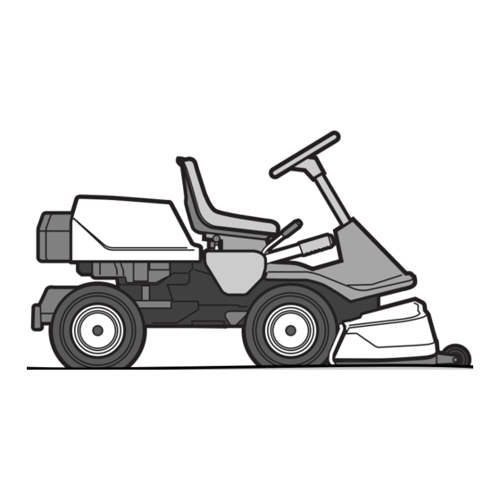
Congratulations on your choice of an exceptionally high quality product. This operator's manual describes Rider ProFlex 21 AWD. Rider ProFlex 21 AWD is fitted with a Kawasaki four- stroke V-Twin engine developing 21 horse power. Rider ProFlex 21 AWD is equipped with power steering and hydraulic lifts. -
Page 16: Placement Of Controls
PRESENTATION Placement of Controls 8009-697 Power outlet 11. Accelerator for reversing Ignition key 12. Accelerator for driving forwards Switch for the power outlet 13. Pedal for parking brake Choke Lever 14. Lock button for parking brake Switch for the lights 15. -
Page 17: Throttle Control
PRESENTATION Throttle Control The throttle is used to control the speed of the engine and thereby also the rotation speed of the blades. In order to increase or decrease the engine speed, the control is moved forwards or backwards respectively. Avoid idling the engine for long periods, as there is a risk of carbon build-up on the spark plugs. -
Page 18: Cutting Unit
PRESENTATION Cutting Unit Rider ProFlex 21 AWD can be equipped with cutting units of the types Combi 112 with a 112 cm cutting width and Combi 122 with a 122 cm cutting width. The Combi unit functions as a BioClip unit when a BioClip plug is fitted, but can be set to rear ejection by... -
Page 19: Cutting Height Adjustment Lever
PRESENTATION Cutting Height Adjustment Lever Using the cutting height lever, the cutting height can be adjusted between seven different positions. It is important that the air pressure in both front wheels is equal, 60 kPa / 0.6 bar / 9 PSI, to produce an even cutting height. -
Page 20: Mechanical Lifting Lever For Cutting Unit
PRESENTATION Mechanical Lifting Lever for Cutting Unit The lever is used as a backup lever to put the cutting unit in either the transport or mowing position when hydraulic pressure is unavailable. It can also be used to mechanically secure the cutting unit in the transport position. -
Page 21: Parking Brake
PRESENTATION Parking Brake The parking brake is activated as follows: Press down the parking brake pedal. Completely depress the lock button on the steering servo housing. Release the parking brake pedal while keeping the button pressed in. The parking brake lock is automatically disengaged when the brake pedal is pressed down. -
Page 22: Clutch Control
PRESENTATION Clutch Control AWD models have separate clutch controls for forward and rear axles. The clutch controls are used to move the Rider when the engine is not running. Pull the controls to the end positions, do not use an intermediate position. -
Page 23: Mowing Tips
DRIVING Mowing Tips WARNING! Clear the lawn of stones and other objects that can be thrown out by the blades. • Localise and mark rocks and other fixed objects in order to avoid collisions. 6007-212 Mowing Patterns • Begin with a high cutting height and reduce it until the desired mowing result is attained. -
Page 24: Clutch Control
DRIVING Clutch Control The clutch controls must be pulled out in order for the Rider to be moved when the engine is shutoff. Should you attempt to drive the machine with the clutch controls pulled out it will not move. The drive on the axle is disengaged when one of the controls is pulled out. -
Page 25: Running
DRIVING Running IMPORTANT INFORMATION The air intake grille in the engine cover behind the driver's seat must not be blocked by, for example, clothing, leaves, grass or dirt. Impaired cooling of the engine. Risk of major engine damage. Before Starting 8009-489 •... - Page 26 DRIVING Move the throttle to the middle position. 8009-562 If the engine is cold, the choke control shall be moved backwards to its end position. 8009-534 Turn the ignition key to the start position. 8009-558 When the engine starts, immediately release the ignition key so that it returns to the neutral position.
-
Page 27: Driving The Rider
DRIVING Move the choke lever gradually forward once the engine has started. 8009-560 Set the desired engine speed with the throttle. Allow the engine to run at a moderate speed, ”half throttle”, for 3-5 minutes before loading it too heavily. WARNING! Never run the engine indoors, in enclosed or badly ventilated areas. -
Page 28: Braking
DRIVING Select the required cutting height (1-7) using the cutting height lever. 8009-539 Depress the lock button on the mechanical lifting lever and move the lever to its most forward position. The cutting unit lowers and starts. 8009-537 If the cutting unit does not lower completely, or if the blades do not rotate, lower the cutting unit completely using the hydraulic lifting lever. -
Page 29: Cutting The Engine
DRIVING Cutting the Engine If the engine has been worked hard, it is preferable to let the engine idle for a minute so it is running at its normal working temperature when it is stopped. Avoid idling the engine for long periods, as there is a risk of carbon build-up on the spark plugs. - Page 30 DRIVING English-...
-
Page 31: Maintenance
MAINTENANCE Maintenance Maintenance Schedule The following is a list of maintenance procedures that must be performed on the Rider. For points marked with footnote numbers 4 or 5, turn to an authorised service representative. G = Described in this manual. ❍= Not described in this manual. - Page 32 MAINTENANCE G = Described in this manual. ❍= Not described in this manual. Maintenance Page Daily Maintenance Weekly main- least interval in hours main- tenance once tenance a year before after Check the air pressure in the tyres (60 kPa) ❍...
- Page 33 MAINTENANCE G = Described in this manual. ❍= Not described in this manual. Maintenance Page Daily Maintenance Weekly main- least interval in hours main- tenance once tenance a year before after ❍ ❍ Inspect the flame arrester/spark extinguisher (extra equipment) Replace the hydraulic oil filter (every 200 hours) Replace the engine oil filter...
-
Page 34: Removing The Rider's Covers
MAINTENANCE Removing the Rider’s Covers Engine cover Push the seat to its most forward position and then tip it back. Turn the cover lock on the top of the engine cover anti-clockwise a 1/4 turn. 8009-509 Open the engine cover. If necessary the engine cover can be lifted off by removing the hinge pins. -
Page 35: Left-Hand Wing Cover
MAINTENANCE Left-hand Wing Cover Loosen the screws (2) and remove the wing cover. 8009-501 Transmission cover Loosen both screws (one on each side) and lift off the transmission cover. 8009-603 Checking the Engine’s Cooling Air Intake Clean the air intake grille in the engine cover behind the driver's seat. -
Page 36: Checking The Transmission Air Intake
MAINTENANCE Checking the Transmission Air Intake Check to ensure that the air intake valve to the transmission is not clogged. 6008-604 Checking and Adjusting the Steering Cables The steering is governed by means of cables. After a period of use these can become stretched, which means the steering setting may have changed. -
Page 37: Checking And Adjusting The Throttle Cable
MAINTENANCE Checking and Adjusting the Throttle Cable Check that the engine responds to throttle increases and that a good engine speed is attained at full throttle. If doubts arise, contact your service representative. If adjustments are necessary, they can be made as follows for the lower cable: Loosen the clamping screw for the cable’s outer casing and move the throttle to the full throttle... -
Page 38: Adjusting The Hydrostatic Transmission Cable
MAINTENANCE Adjusting the Hydrostatic Transmission Cable The hydrostatic transmission cable (on the left side) is adjusted in the following manner: Remove the transmission cover. Loosen both screws (one on each side) and lift off the transmission cover. Take apart the ball joint, which is locked with a locking spring. -
Page 39: Adjusting The Parking Brake
MAINTENANCE Adjusting the Parking Brake Check that the parking brake is adjusted correctly by placing the machine on a slope with the front and rear axles disengaged. Apply and lock the parking brake. When the machine does not standstill, the parking brake should be adjusted according to the following. -
Page 40: Replacing The Air Filter
MAINTENANCE Replacing the Air Filter If the engine seems to lack power or does not run smoothly this may be because the air filter is clogged. If run with a soiled air filter, carbon can build-up on the spark plugs and lead to malfunction. For this reason, it is important to replace the air filter regularly (see ”Maintenance Schedule”... - Page 41 MAINTENANCE Tap the paper filter against a solid surface to remove dust. If the paper filter is still dirty, it must be replaced. IMPORTANT INFORMATION Do not use compressed air to clean the paper filter. Do not wash the paper filter. Do not oil the paper filter.
-
Page 42: Replacing The Fuel Filter
MAINTENANCE Replacing the Fuel Filter Replace the fuel filter mounted on the supply line after every 100 hours (once per season) or more frequently if it is clogged. Replace the filter as follows: Open the engine cover. Move the hose clamps away from the filter. Use a pair of flat pliers. -
Page 43: Checking The Tyre Pressures
MAINTENANCE Checking the Tyre Pressures The tyre pressure should be 60 kPa / 0.6 bar / 9 PSI on all wheels. Highest permitted pressure = 80 kPa / 0.8 bar / 12 PSI. IMPORTANT INFORMATION Different air pressure in the front tyres will result in the blades mowing the grass at different heights. -
Page 44: Fuses
MAINTENANCE Replacing the Spark Plug Remove the ignition cable shoe and clean around the spark plug. Remove the spark plug with a 13/16" (21 mm) spark plug socket wrench. Check the spark plug. Replace the spark plug if the electrodes are burned or if the insulation is cracked or damaged. -
Page 45: Checking The Safety System
MAINTENANCE Checking the Safety System The Rider is equipped with a safety system that prevents starting or driving under the following conditions. The engine should only be possible to start when the cutting unit is in its raised position and the parking brake is applied. -
Page 46: Replacing The Light Bulbs
MAINTENANCE Replacing the Light Bulbs For information about the bulb type, see ”Technical Data”. Unscrew the two screws holding the cover on the power servo housing. Lift up the cover and turn it around the steering shaft. 8009-511 Unscrew the two screws holding the lamp insert. Lift out the lamp insert. -
Page 47: The Cutting Unit Components
MAINTENANCE The Cutting Unit Components In the instructions below, a cutting unit with a rear ejector is shown, but the same principles apply to all cutting units unless otherwise stated. The components mentioned are: • A Catch • B Inner pin •... - Page 48 MAINTENANCE Attach the unit to the equipment frame’s outer hooks. 8009-024 Pull out the catch (A) and loosen the safety catch by pushing its handle (D) back. 8009-167 Raise the unit by pulling up the mechanical lifting lever, located on the driver’s right side. Push the unit in so that the interior plugs (B) touch the bottom of the equipment frame’s grooves.
- Page 49 MAINTENANCE Loosen the belt tensioner spring and attach the belt to the front belt pulley. A new belt is short. Turn the forward pulley as needed with a spanner on the central bolt. 8009-008 Refit the belt tensioner spring. IMPORTANT INFORMATION Check that the belt is around the idler.
-
Page 50: Adjusting The Cutting Height, Parallelism And Ground Pressure
MAINTENANCE Adjusting the Cutting Height, Parallelism and Ground Pressure When a new cutting unit is attached, you need to adjust the cutting height, parallelism and ground pressure. Adjustment must be made in the stated order. Starting position: • Check the air pressure in the tyres 60 kPa / 0.6 bar / 9 PSI. -
Page 51: The Cutting Unit's Service Position
MAINTENANCE Ground pressure In order to achieve the best mowing result the cutting unit should follow the ground without touching it too heavily. Pressure is adjusted using a screw and spring on each side of the rider. Adjust the cutting unit’s ground pressure in the following manner: Place a set of bathroom scales under the cutting unit’s frame (on the front edge) so that the unit... -
Page 52: Cutting Unit Model
MAINTENANCE Cutting Unit Model ProFlex can be equipped with two different types of cutting unit: • Combi 112 • Combi 122. Other cutting units cannot be mounted without changing the drive belt. 8009-288 Combi 112 8009-290 Combi 122 Checking the Blades It is important that the blades are undamaged and well- ground to give the best mowing result. -
Page 53: Removing The Cutting Unit
MAINTENANCE Removing the Cutting Unit WARNING! Exercise caution. Risk of crush injuries. Place the machine on a flat surface. Lock the brake by pressing down the pedal and locking with the push-button. 8009-328 Lift the cutting unit with the mechanical lifting lever. - Page 54 MAINTENANCE Unhook the height adjustment strut (E) by moving the rear part upwards: Unload the strut if necessary by pulling the frame’s forward section up or down. 8009-169 10. Pull the handle (D) and unit simultaneously. Release the handle when the unit has come out a bit.
-
Page 55: Removing The Unit Frame
MAINTENANCE Removing the Unit Frame Starting position for removing the cutting unit frame: • Cutting unit removed. Twist the catch out so that the forward fastener can be lifted from the cutting unit. 8009-184 Move the unit frame backwards so that the tongue of the cutting unit releases its grip on the bar of the unit frame and lift the frame off. - Page 56 MAINTENANCE Remove the belt guide for the centre belt. 8009-727 Pull off the centre belt from the engine's pulley and pull out the rear section. Used belts can be pulled downwards. When the belt is new, the centre belt must be pulled off of its front pulley whereupon it can be moved downwards from the engine pulley so that the rear part can be pulled out.
- Page 57 MAINTENANCE Pull the pump belt off of the engine's pulley and move it under the engine belt pulleys. Pull out the pump belt through the opening under the pivot bearing and past the belt tensioner's disc. Assembly 8009-640 10. Pull the pump belt through the opening under the pivot bearing and on the outside past the belt tensioner's disc.
-
Page 58: Replacing The Centre Belt
MAINTENANCE 16. Fit the belt guide for the centre belt. 8009-727 17. Hook the spring on the belt tensioner. 8009-637 Replacing the Centre Belt On Rider 21 AWD the spring-loaded belt guide under the blade brake on the centre pulley must be pressed in to be moved past the centre belt. -
Page 59: Replacing The Front Belt
MAINTENANCE Replacing the Front Belt Dismantling The entire belt is removed according to the following when a snow blade is to be attached to the machine. Remove the cutting unit and hang the front part of the belt around the safety catch handle. 8009-613 Press the guide plate down under the anti-scalp roller and push out the belt. - Page 60 MAINTENANCE Assembly Check, before assembling, that the new belt is the correct length (compare with the old). Place the forward part of the front belt in place and hang the forward part around the handle of the safety catch. Position the front belt on the centre pulley's upper groove.
-
Page 61: Changing The Cutting Unit's Belt
MAINTENANCE Changing the Cutting Unit’s Belt WARNING! Protect your hands with gloves when working with the blades. There is a risk of crush injuries when working with the belt. Changing the belt on the Combi unit On these cutting units with ”collision-proof” blades, the 8009-005 blades are driven by one V-belt. -
Page 62: Removal Of Bioclip Plug
MAINTENANCE Removal of BioClip Plug To change a Combi unit from the BioClip function to a cutting unit with rear ejection, remove the BioClip plug, which is located under the unit, attached with three screws. Put the unit in service position, see ”The Cutting Unit’s Service Position”... -
Page 63: Lubrication
LUBRICATION Lubrication Lubrication Schedule When in daily use, the weekly lubrication (1/52) schedule should be carried out twice a week. 8009-680 The position numbers for the lubrication points refer to the lubrication instructions on the following pages. English-... -
Page 64: General
LUBRICATION General Remove the ignition key to prevent unintentional movements during lubrication. When lubricating with an oilcan, it ought to be filled with engine oil. When lubricating with grease, unless otherwise stated, grease 503 98 96-01 or another chassis or ball bearing grease offering good corrosion protection shall be used. -
Page 65: Lubricating In Accordance With The Lubrication Schedule
LUBRICATION Lubricating in Accordance with the Lubrication Schedule The numbers in the following headings refer to the lubrication points as described in ”Lubrication Schedule” on page 61 and ”General” on page 62. 1. Pedal Mechanism in Frame Tunnel Lubricate the pedal mechanism in the frame tunnel. Remove the cover of the frame tunnel by loosening the screws (two on the steering servo housing). -
Page 66: Parking Brake Cable
LUBRICATION 3. Parking Brake Cable Remove the cover from the frame tunnel, see ”1. Pedal Mechanism in Frame Tunnel” on page 63. Lubricate both ends of the cable. Remove the cable’s rubber casing when lubricating. Lubricate the cable with an oil can, press the parking brake pedal a few times and lubricate again. -
Page 67: Engine Oil
LUBRICATION 5. Engine Oil Check the oil level in the engine when the Rider stands horizontal with the engine switched off. Open the engine cover. Remove the dipstick and wipe it clean. Now insert the dipstick again, without tightening it. Take the dipstick out again and read the oil level. - Page 68 LUBRICATION Replacing the engine oil The engine oil should be changed the first time after 8 hours running time. It should then be changed after every 100 hours of running time. WARNING! Engine oil can be very hot if it is drained directly after stopping the engine.
-
Page 69: Hydrostatic Cable
LUBRICATION 6. Hydrostatic Cable Remove the transmission cover, two screws. 8009-603 Remove the rubber casing and lubricate the hydrostatic transmission cable with an oilcan. Press the pedal a few times and lubricate again. Replace the rubber cover. Replace the transmission cover. 8009-692 7. -
Page 70: Throttle And Choke Cables, Lever Bearings
LUBRICATION 9. Throttle and Choke Cables, Lever Bearings Remove the right side cover on the lever housing (2 screws) and open the engine cover. Lubricate the cables’ free ends with the oilcan, even those by the carburettor. Move the controls to the end points and lubricate again. -
Page 71: Oil Filter, Change
LUBRICATION 11. Oil Filter, Change WARNING! Engine oil can be very hot if it is drained directly after stopping the engine. Allow the engine to cool somewhat first. IMPORTANT INFORMATION Used engine or transmission oil is health- impairing and must not be disposed of in the ground or in nature. -
Page 72: Hydraulic System's Oil Level
LUBRICATION 13. Hydraulic System's Oil Level Remove the transmission cover. Make sure the machine is parked on even ground. Check the oil level, it should be visible in the sight glass at 20°C. Unscrew the oil container’s cover and fill with SAE 10W/40 engine oil, class SF-CC, until the oil level reaches the top of the sight glass. -
Page 73: Trouble Shooting Guide
TROUBLE SHOOTING Trouble Shooting Guide Problem Cause The engine will not start. • Fuel tank empty • Incorrect fuel type • Faulty spark plugs • Faulty spark plug connections • Dirt in the carburettor or fuel line Starter does not turn the engine •... -
Page 74: Trouble Shooting
TROUBLE SHOOTING Problem Cause Engine overheating • Engine overloaded • Air intake or cooling fins clogged • Damaged fan • Too little or no oil in the engine • Faulty pre-ignition • Faulty spark plugs Battery does not charge • One or more battery cells faulty •... -
Page 75: Storage
STORAGE Storage Winter Storage At the end of the mowing season, the Rider should be readied for storage, likewise if it will not be in use for more than 30 days. Fuel allowed to stand for long periods of time (30 days or more) can leave sticky residues that can clog the carburettor and disrupt engine function. -
Page 76: Service
When ordering spare parts, please specify the purchase year, model, type, and serial number of the Rider. Always use genuine Husqvarna spare parts. An annual check-up or trimming at an authorised service representative is a good way to ensure that your Rider performs at its best the following season. -
Page 77: Electrical System
ELECTRICAL AND HYDRAULIC SYSTEMS Electrical System 8009-678 Electrical system: component locations Numbers correspond to: Colour abbreviations: Microswitch, hydrostatic transmission RD = Red BL = Blue Microswitch, cutting unit VT = White Microswitch, seat SV = Black Ignition key GL = Yellow Chronometer GR = Grey Start relay... - Page 78 ELECTRICAL AND HYDRAULIC SYSTEMS 8009-679 Electric system English-...
-
Page 79: Hydraulic System
ELECTRICAL AND HYDRAULIC SYSTEMS Hydraulic System 8009-357 Hydraulic system for the power steering and unit lift: component locations Hydraulic system: component locations: Power steering Pneumatic cylinder Pump Pressure limiting valve Hydraulic oil filter Control valve for pneumatic cylinder Keep the hydraulic system clean. Remember to: •... - Page 80 ELECTRICAL AND HYDRAULIC SYSTEMS English-...
-
Page 81: Technical Data
TECHNICAL DATA Technical Data Data Rider ProFlex 21 AWD Dimensions Length, base machine 2080 mm / 6.82 ft Width, base machine 900 mm / 2.95 ft Height 1160 mm / 3.80 ft Operating weight, base machine 329 kg / 725 lb Wheelbase 1000 mm / 3.28 ft... - Page 82 TECHNICAL DATA Data Rider ProFlex 21 AWD Hydraulic System Max. working pressure 300 bar/4200 PSI Power steering circuit max. working pressure 45 bar/630 PSI Transmission Manufacturer and type Front Kanzaki VFMU KTM 10 Rear Kanzaki RMU KTM 10 SAE 10W/40, class SF-CC...
-
Page 83: Eu Declaration Of Conformity
Husqvarna AB, SE-561 82 Huskvarna, Sweden, tel: +46-36-146500, declares under sole responsibility that Rider Husqvarna Rider ProFlex 21 AWD dating from 2005 serial numbers and onwards (the year is clearly stated on the rating plate, followed by the serial number), complies with the requirements of the COUNCIL’S DIRECTIVE:... - Page 84 EU DECLARATION OF CONFORMITY English-...
-
Page 85: Service Journal
SERVICE JOURNAL Service Journal Action Delivery Service Fill the battery with battery acid and charge for four hours. Fit the steering wheel, seat and, where applicable, other components. Attach the cutting unit. Adjust the cutting unit: Adjust the lifting springs (the ”weight” of the cutting unit should be 12-15 kg, if a brush is to be used, set to maximum spring force). - Page 86 SERVICE JOURNAL Action Date, mileage reading, stamp, signature 25-Hour Service Clean the air cleaner’s pre-filter (foam element). Notes (shorter intervals for dusty operating conditions) Clean the engine’s cooling air intake and the transmission’s air intake. Clean the fuel pump’s air filter. (for dusty operating conditions) Check the mounting bolts on the muffler.
- Page 87 SERVICE JOURNAL Action Date, mileage reading, stamp, signature 50-Hour Service Clean/change the air cleaner’s pre-filter (foam element). Notes (shorter intervals for dusty operating conditions) Clean the engine’s cooling air intake and the transmission’s air intake. Clean the fuel pump’s air filter. Check the mounting bolts on the muffler.
- Page 88 SERVICE JOURNAL Action Date, mileage reading, stamp, signature 100/200-Hour Service Change engine oil. Replace the oil filter every 200 hours. Notes Clean/change the air cleaner’s pre-filter (foam element). Clean the air cleaner’s paper filter. Replace every 200 hours. (shorter intervals for dusty operating conditions) Clean the engine’s cooling air intake and the transmission’s air intake.
- Page 89 SERVICE JOURNAL Action Date, mileage reading, stamp, signature 300-Hour Service Inspect the machine. Additional work? Notes Change engine oil. Change the air filter (foam element). Change the air filter (paper filter). Clean the fuel pump’s air filter. Check the mounting bolts on the muffler. Check/adjust the cutting height.
- Page 90 SERVICE JOURNAL Action Date, mileage reading, stamp, signature At Least Once Each Season Change the engine oil (100 hours). Notes Clean/change the air cleaner’s pre-filter (foam element) (25 hours). (shorter intervals for dusty operating conditions) Clean/change the air filter’s paper filter (100 hours). (shorter intervals for dusty operating conditions) Clean the fuel pump’s air filter (50 hours).
- Page 91 SERVICE JOURNAL Action Date, mileage reading, stamp, signature English-...
- Page 92 SERVICE JOURNAL Action Date, mileage reading, stamp, signature English-...
- Page 94 ´®z+RÆ^¶6.¨...
- Page 96 115 00 06-26 ´®z+RÆ^¶6.¨ 2005W05...
Need help?
Do you have a question about the Rider ProFlex 21 AWD and is the answer not in the manual?
Questions and answers