Table of Contents
Advertisement
Quick Links
Advertisement
Table of Contents

Related Manuals for HBM T10FH


Summary of Contents for HBM T10FH
- Page 1 Mounting instructions Torque Flange T10FH A2037 4.0 en...
-
Page 3: Table Of Contents
T10FH Safety instructions .......... - Page 4 12 Dimensions Rotor T10FH rotating; option 2, code L ... . . 13 Dimensions Rotor T10FH non rotating; option 2, code N ..
-
Page 5: Safety Instructions
Safety instructions Appropriate use The T10FH Torque Flange may be used for torque measurement and directly related control and regulation tasks only. Any other use is not appropriate. To ensure safe operation, the transducer may only be used according to the specifications given in this manual. - Page 6 Means that important information about the product or its handling is being given. Symbol: Meaning: CE mark The CE mark enables the manufacturer to guarantee that the product com plies with the requirements of the relevant EC directives (the declaration of conformity is available at http://www.hbm.com/HBMdoc). A2037−4.0 en...
- Page 7 Reconstruction and modifications HBM’s express consent is required for modifications affecting the transducers’ construction and safety. HBM does not take responsibility for damage result ing from unauthorized modifications. Qualified personnel The transducers may be used by qualified personnel only; the technical data and the special safety regulations must be observed in all cases.
- Page 8 T10FH Prevention of accidents According to prevailing accident prevention regulations, after fitting the T10FH torque flange a cover must be fitted as follows: • The cover must not be able rotate. • The cover shall protect against crushing or cutting and provide protection against parts that might come loose.
-
Page 9: Scope Of Supply
PTB calibration certificate in accordance with DIN 51 309 or EA 10/14: Class 0.5 Application The T10FH torque flange records static and dynamic torque on fixed or rotat ing shafts and also return RS422 signals with direction of rotation information to determine the speed. -
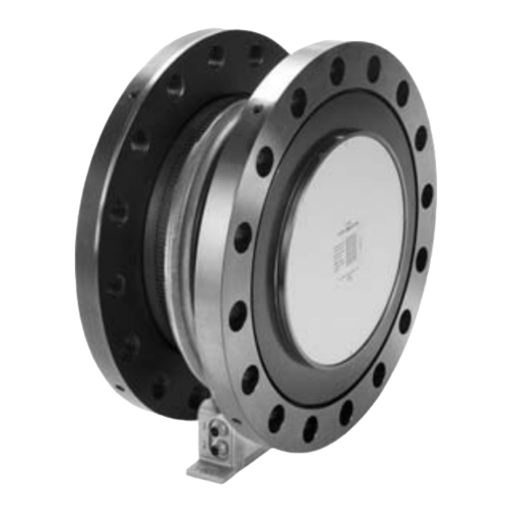
Page 10: Structure And Mode Of Operation
T10FH Structure and mode of operation The torque flange (Option 2, code N) consists of two separate parts: the rotor and the stator. The rotor comprises the measuring body and the signal transmission ele ments. Strain gages (SGs) are mounted on the measuring body. The rotor electronics for transmitting the excitation voltage and the measurement signal are located centrally in the flange. -
Page 11: Mechanical Installation
(medium strength) to exclude prestressing loss due to screw slackening. An appropriate shaft flange enables the T10FH torque flange to be mounted directly. It is also possible to directly mount a joint shaft or relevant compen sating elements on the opposite flange (using an intermediate flange when re quired). -
Page 12: Conditions On Site
T10FH 4.1 Conditions on site The T10FH torque flange is protected to IP54 according to EN 60529. Protect the transducer from coarse dirt, dust, oil, solvents and moisture. During opera tion, the prevailing safety regulations for the security of personnel must be ob served (see "Safety Instructions"). - Page 13 T10FH CAUTION When installing the rotor, make sure that you do not damage the stator. It is essential in this case to comply with the notes on assembling the antenna segments (see "Installing the stator", page 21). Customer mounting 1. Install rotor 2.
- Page 14 T10FH Support supplied by customer Clamp fixture 5. Align stator and finish installation 6. Install clamp fixture A2037−4.0 en...
-
Page 15: Preparing For The Rotor Mounting
1. Remove the top layer of foam packaging. Fig. 4.1: T10FH packaging 2. Fasten two equal−length ropes of sufficient bearing strength to the eye bolts (each of the two ropes must be able to bear the full weight of the ro tor) and hoist the rotor out of its packaging with the crane (see Fig. - Page 16 T10FH Fig. 4.2: Hoist the rotor out of its packaging 3. Place the rotor onto a clean and stable base. 4. Remove one of the eyebolts. 5. Carefully lift the rotor until it hangs freely. 6. Carefully tilt the rotor by lowering it over the flange edge until it rests hori zontally on both outer flange surfaces (see Fig.
- Page 17 T10FH Fig. 4.3: Tilt rotor 7. Secure the rotor with wedges to stop it rolling away. 8. Screw the second eyebolt back into the tapped holes in the outer flange surface. 9. Fasten the rotor to the hook of the crane with two equal−length ropes. The rotor is now prepared for horizontal installation (see Fig.
- Page 18 T10FH Fig. 4.4: Fastening for horizontal installation CAUTION You must remove the eyebolts after mounting! Keep them safe for later use. A2037−4.0 en...
-
Page 19: Mounting The Rotor
T10FH 4.5 Mounting the rotor NOTE In general, the rotor identification plate is no longer visible after installa tion. This is why we include with the rotor additional stickers with the important ratings, which you can attach to the stator or any other rele vant test−bench components. - Page 20 T10FH WARNING With alternating load: Use a screw locking device (e.g. LOCTITE no. 242) to cement the screws into the mating thread to exclude prestressing loss due to screw slackening. 3. Tighten all screws with the specified tightening torque (Tab. 4.1).
-
Page 21: Installing The Stator
T10FH 4.6 Installing the stator On delivery, the stator has already been fitted ready for operation. The an tenna segments have to be separated for installation. To stop you modifying the center alignment of the segment rings opposite the base of the stator, we recommend that you separate only one antenna segment from the stator. - Page 22 T10FH 4. Align the antenna and rotor so that the antenna encloses the rotor coaxi ally. Please observe the permissible alignment tolerances stated in the specifications. 5. Now fully tighten the screw fitting of the stator housing. 6. Make sure that the gap in the lower antenna segment area is free of electrically conductive foreign bodies.
-
Page 23: Installing The Clamp Fixture
T10FH 4.7 Installing the clamp fixture Depending on the operating conditions, the antenna ring may be excited to vi brate. This effect is dependent on • the speed • the antenna diameter (depends in turn on the measuring range) • the design of the machine base To avoid vibrations, a clamp fixture is enclosed with the torque flange enabling the antenna ring to be supported. -
Page 24: Aligning The Stator (Speed Measuring System)
T10FH Support supplied by customer Clamp fixture Antenna ring Fig. 4.8: Supporting the antenna ring 4.8 Aligning the stator (speed measuring system) The stator can be mounted in any position (for example, "upside down" instal lation is possible). For measuring mode to operate perfectly, the speed sensor must be placed at a defined position to the rotor ring gear. - Page 25 T10FH Ring gear Axial alignment Radial distance Speed sensor Fig. 4.9: Position of the sensor head to the ring gear Radial alignment The rotor axis and the axis of the speed sensor must be along a line at right angles to the stator platform. The radial distance is critical for the radial align ment (see Fig.
-
Page 26: Electrical Connection
Avoid transformers, motors, contactors, thyristor controls and similar stray− field sources. CAUTION Transducer connection cables from HBM with attached connectors are identified in accordance with their intended purpose (Md or n). When cables are shortened, inserted into cable ducts or installed in control cabinets, this identification can get lost or become concealed. -
Page 27: Connector Pin Assignment Option 3, Code Su2
Option 3, SU2 torque transducers are only intended for operation with a DC supply voltage (separated extra−low voltage). They must not be con nected to older HBM amplifiers with square−wave excitation. This could lead to the destruction of the connection board, or other errors in the amplifiers (the torque flange, on the other hand, is protected and once the proper connections have been re−established, is ready for operation... - Page 28 T10FH Assignment for connector 2: Speed measuring system Connec Assignment Color SubD Binder 723 code connec tor Pin Speed measurement signal (pulse string, 5 V ; 0°) − − no function Speed measurement signal (pulse string, 5 V 90° phase shifted) no function −...
-
Page 29: Connector Pin Assignment Option 3, Code Pnj
, additional precautions must be taken to discharge excess volt ages. 5.5.1 Supply voltage for self−contained operation The information in this section relate to the standalone operation of the T10FH without HBM system solutions. Supply voltage is electrically isolated from signal outputs and shunt signal in puts.V) up to 50... -
Page 30: Supply Voltage (Option 3, Code Pnj)
The digital identification system is available at plug connection PIN 7 to PIN 2. The HBM TEDS Editor is used to store the data. This is included in the HBM "MGCplus Setup Assistant" software. You can use the Editor to manage differ ent user rights, thus protecting the essential transducer data from being over written by mistake. -
Page 31: Administrator Rights (Id Level)
The base area (basic TEDS), to the configuration defined in standard IEEE1451.4. The transducer type, the manufacturer and the transducer serial number are contained here. Example: TEDS content with the identity number for the T10FH/150 kN@m sensor with serial no. 123456, made in November 2005 TEDS Manufacturer... - Page 32 Area 3: Data specified by the manufacturer and the user are contained in this area: For the T10FH torque flange, HBM has already described the Bridge Sensor and Channel name templates. Additional templates, such as the Signal Conditioning template, can also be described by the user.
- Page 33 0 to 2047. If that is not enough, the HBM Channel Comment template can also be used for this purpose. Typical values for an HBM T10FH/150 kN@m torque flange Template: HBM Channel Name Channel name T10FH/150 kNm When the manufacturer creates the Bridge Sensor template, the physical measured quantity and the physical unit are defined.
-
Page 34: Shunt Signal (Option 3, Code Su2)
T10FH Shunt signal (Option 3, Code SU2) The T10FH torque flange delivers a shunt signal that can be switched at the amplifier end for measurement chains with HBM components. The measure ment flange generates a shunt signal of about 50% of the nominal (rated) torque. -
Page 35: Settings (Option 3, Code Su2)
T10FH Settings (Option 3, Code SU2) 8.1 Torque output signal The factory setting for the frequency output voltage is 5 V (symmetrical, com plementary RS422 signals). The frequency signal is on pin 4 opposite pin 1. You can change the output voltage to 12 V (asymmetrical). To do this, change switches S1 and S2 to position 1 (and pin 1 →... -
Page 36: Function Testing
T10FH End point Zero point Fig. 8.2: Setting the voltage output zero point 8.3 Function testing 8.3.1 Power transmission If you suspect that the transmission system is not working properly, you can remove the stator cover and test for correct functioning. If the LED is on, the rotor and stator are properly aligned and there is no interference with the transmission of measurement signals. -
Page 37: Checking The Speed Measuring System
T10FH 8.3.2 Checking the speed measuring system If required, you can check that the speed measuring system is functioning cor rectly. 1. Remove the cover of the stator housing. −1 2. Turn the rotor by at least 2 min If both the control LEDs come on while you are turning the rotor, the speed measuring system is properly aligned and fully operational. -
Page 38: Speed Measuring System
T10FH 8.4 Speed measuring system For optimum functionality, all the DIP−switches (S1−S6) for the speed mea suring system must be in the "OFF" position (factory setting). Switches S1 ... S6 Fig. 8.5: Switches for setting the speed measuring system 8.5 Form of speed output signal In the factory setting, two 90_ phase−offset speed signals (5 V symmetrical,... -
Page 39: Loading Capacity
The torque transducer is suitable for measuring static and dynamic torques. The following applies to the measurement of dynamic torque: • The T10FH calibration performed for static measurements is also valid for dynamic torque measurements. • The natural frequency f... -
Page 40: Maintenance
T10FH Vibration bandwidth Upper maxi mum torque Lower maxi mum torque Fig. 9.1: Permissible dynamic loading Maintenance The T10FH torque flange is maintenance free. A2037−4.0 en... -
Page 41: Specifications
T10FH Specifications Type T10FH (rotating); option 2, code L Accuracy class Torque measuring system Nominal (rated) torque M kN⋅m for reference only kft lb 73.8 95.9 110.6 147.5 184.4 221.3 Nominal (rated) sensitivity (range between torque = zero and nominal... - Page 42 T10FH Type T10FH (rotating); option 2, code L Nominal (rated) torque M kN⋅m for reference only kft lb 73.8 95.9 110.6 147.5 184.4 221.3 Temperature influence per 10 K in the nominal temperature range Residual ripple related to nominal (rated) sensiti...
- Page 43 T10FH Type T10FH (rotating); option 2, code L Speed measuring system Measuring system Magnetic field dependent resistor and gear ring Mechanical increments (pulses per revolution) 5 symmetric 2 x 180 square wave signals approx. 90° phase Output signal shifted Minimum speed for sufficient...
- Page 44 T10FH Type T10FH (non rotating); option 2, code N Accuracy class Torque measuring system Nominal (rated) torque M kN⋅m for reference only kft lb 73.8 95.9 110.6 147.5 184.4 221.3 Nominal (rated) sensitivity at (nominal (rated) signal range bet ween torque= zero and nominal mV/V 1.1 ...
- Page 45 T10FH General data Nominal (rated) torque M kN⋅m for reference only kft lb 73.8 95.9 110.6 147.5 184.4 221.3 EME (Emission per EN61326−1, table 4) RFI field strength − Class B Immunity from interference (EN61326 1, table A.1) Electromagnetic field AM...
- Page 46 T10FH Nominal (rated) torque M kN⋅m for reference only kft lb 73.8 95.9 110.6 147.5 184.4 221.3 Load limits Limit torque kN⋅m Breaking torque kN⋅m > 300 > 600 Axial limit force Lateral force limit Bending limit moment kN⋅m Oscillation bandwidth per kN⋅m...
- Page 47 T10FH Mechanical values Nominal (rated) torque M kN⋅m for reference only kft lb 73.8 95.9 110.6 147.5 184.4 221.3 Torsional stiffness c kN⋅m/rad 84000 169500 Axial stiffness c kN/mm 1250 2850 Radial stiffness c kN/mm 2500 4300 Stiffness with bending moment...
-
Page 48: Dimensions Rotor T10Fh Rotating; Option 2, Code L
T10FH Dimensions Rotor T10FH rotating; option 2, code L K stator center 150 +2 approx. 100 Section A A (Partial section: Flange bore and centering) = measuring plane (center of point of application) Dimensions in mm Measuring range (kNVm) ∅d ∅d... -
Page 49: Dimensions Rotor T10Fh Non Rotating; Option 2, Code N
T10FH Dimensions Rotor T10FH non rotating; option 2, code N Flange illustration for measuring range 100 kNVm to 150 kNVm min. bending radius R=20 ø395 Section A A ø395 (Partial section: Internal centering Section B B (Partial section: Connector) = measuring plane (center of point of application) Flange illustration for measuring range of 200 kNVm to 300 kNVm min. -
Page 50: Mounting Dimensions
T10FH 14 Mounting Dimensions Mounting dimensions Measuring range Area free of metal part "a" (kNVm) (mm) 100 ... 300 A2037−4.0 en... -
Page 51: Supplementary Technical Information; Option 2, Code L
T10FH Supplementary technical information; option 2, code L 15.1 Output signals 15.1.1 Output MD for torque (connector 1) Symmetrical output signals (factory setting) symmetrical Pos.2 Plug 1 10 V Differential inputs Asymmetrical output signals 12 V 12 V asymmetrical Pos.1 Plug 1 A2037−4.0 en... -
Page 52: Output N For Rotation Speed (Connector 2)
T10FH 15.1.2 Output N for rotation speed (connector 2) Symmetrical output signals (factory setting) Plug 2 symmetrical Pos.2 Switch S7 10 V Differential inputs Asymmetrical output signals asymmetrical Plug 2 Switch S7 Pos.1 A2037−4.0 en... -
Page 53: Circular Run−Out Values
T10FH 15.2 Circular run−out values 0.02 AB 0.02 AB Internal centering Flange A Flange B Hardness 46 ... 54 HRC Surface quality of in−plane and concentric surfaces (A, B and AB) A2037−4.0 en... -
Page 54: Order Number
0.1 % Option 1, Code 100R ... 150R: 0.25 % Option 1, Code 200R ... 300R: 0.4 % Order no.: K T10FH − Ordering example: 1 5 0 R S U 2 K T10FH − A2037−4.0 en... -
Page 55: Accessories
T10FH Accessories Item Order No. Ready made connecting cables Torque (rotating); option 2, code L Connecting cable torque, Binder 423 7 pole − D Sub 15 pole, 6 m 1−KAB149−6 Connecting cable torque, Binder 423 − free ends, 6 m 1−KAB153−6... - Page 56 Hottinger Baldwin Messtechnik GmbH 7 2002.2037 Im Tiefen See 45, D 64293 Darmstadt Tel.: +49 6151 803 0 Fax: +49 6151 803 9100 Email: support@hbm.com Internet: www.hbm.com A2037 4.0 en...
Need help?
Do you have a question about the T10FH and is the answer not in the manual?
Questions and answers