
Related Manuals for HBM T10F


Summary of Contents for HBM T10F
- Page 1 Electrical measurement of mechanical HBM Mess- und Systemtechnik GmbH quantities Mounting instructions Torque flange T10F...
-
Page 3: Table Of Contents
T10F Contents Page Notes on safety .......... -
Page 4: Notes On Safety
Notes on safety Appropriate use The T10F Torque Flange may be used for torque-measurement and directly related control and regulation tasks, only. Any other use is not appropriate. To ensure safe operation, the transducer may only be used according to the specifications given in this manual. - Page 5 T10F In this manual, the below symbols are used to refer to residual dangers: DANGER Symbol: Meaning: Maximum danger level Warns of an imminently dangerous situation in which failure to comply with safety requirements will result in death or serious physical injury.
- Page 6 Prevention of accidents According to the prevailing regulation to prevent accidents a cover has to be fitted after the mounting of the torque transducers T10F as follows: Ÿ the cover must be stationary Ÿ the cover shall avoid any danger of squeezing and provide protection against parts that might come loose Ÿ...
-
Page 7: Application
T10F Application The T10F Torque Flanges measure static and dynamic torques on stationary or rotating shafts. Due to their extremely short design they enable very compact test arrangements to be used. They offer a very wide range of applications. In addition to conventional test-rig applications (motor, roller and gear test-rigs) new solutions for torque measurements partly integrated into the machines are possible. -
Page 8: Design And Function
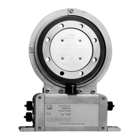
T10F Design and function Strain gauges (S/G) have been mounted on the measuring body. The rotor electronics for bridge-excitation-voltage and measuring-signal transmission is located centrically in the flange. The transmitter coils for the non-contact transmission of excitation voltage and measuring signal are located on the measuring body’s outer circumference. -
Page 9: Mechanical Installation
An appropriate shaft flange enables the T10F Torque Flanges to be mounted directly. The adapter flange enables direct mounting of a cardan shaft or corresponding corrector elements (if necessary, via intermediate flange). -
Page 10: Conditions At The Site Of Installation
T10F Conditions at the site of installation The T10F Torque Flanges are protected to IP54 according to EN 60 529. The measuring hubs must be protected from dirt, dust, oil, solvants and humidity. During operation, the prevailing safety regulations for the security of personnel must be observed (see ”Notes on safety”). -
Page 11: Installation Possibilities
T10F 3.3 Installation possibilities On principle, there are two possibilities for torque-flange mounting: with antenna ring complete or disassembled. We recommend to proceed as described in chapter 3.3.1. If installation according to 3.3.1 is not possible, the stator must be disassembled. For this, do in any case observe the notes on antenna-segment mounting (see ”Installing the stator”). -
Page 12: Installation With Subsequent Stator Mounting
T10F 3.3.2 Installation with subsequent stator mounting Customized stator fastening device 1. Install rotor 2. Install shafting 3. Dismount one antenna segment 4. Install antenna segment around shafting Support supplied by customer Clamping piece 5. Align stator and finish installation 6. -
Page 13: Installation Example With Couplings
T10F 3.3.3 Installation example with couplings Fig. 3.1: Installation example with coupling 3.3.4 Installation example with cardan shaft Fig. 3.2: Installation example with cardan shaft... -
Page 14: Installing The Rotor
T10F 3.4 Installing the rotor NOTE In general, the rotor type-plate will no longer be visible after installation. Therefore, additional adhesive labels including the major characteristics have been supplied; they can be fixed on the stator or other relevant test-rig components thus enabling required data such as e.g. the calibration signal to be read off at any time. - Page 15 T10F 2. Use eight DIN912 hexagon-socket screws, property class 10.9 (measuring range 10kNm: 12.9), of the appropriate length (depending on the connection geometry, see Tab. 3.1) to screw-fasten the measuring body. We recommend, particularly for 50Nm, 100Nm and 200Nm situations, fil-...
- Page 16 T10F CAUTION With alternating loads, use screw locking device to glue into place the connection screws. Guard against contamination from varnish frag- ments. Do in any case observe the maximum thread reach specified in Tab. 3.1. Otherwise, considerable measurement errors might occur or the transducer might suffer damage.
-
Page 17: Installing The Stator
T10F 3.5 Installing the stator On delivery, the stator has already been installed and is ready for operation. The antenna segments can be separated from the stator, for example, for maintenance or to facilitate stator installation. If your application does not require stator disassembly, proceed as described in sections 2., 6., 7. -
Page 18: Installing Protectors
DANGER According to the prevailing regulation to prevent accidents a cover has to be fitted after the mounting of the torque transducers T10F as follows: Ÿ the cover must be stationary Ÿ the cover shall avoid any danger of squeezing and provide protection against parts that might come loose Ÿ... -
Page 19: Clamping Piece Assembly
T10F 3.7 Clamping piece assembly Depending on the operating conditions, the antenna ring may be excited to vibrate. This effect is dependent on Ÿ the speed, Ÿ the antenna diameter (depends in turn on the measurement range), Ÿ the construction of the machine foundations. - Page 20 T10F Assembly sequence 1. Loosen and remove the upper antenna segment screws. 2. Fasten the clamping piece with the enclosed screws as shown in Fig. 3.6. It is essential to use the new serrated locking washers. 3. Clamp a suitable supporting element (we recommend a threaded rod of 3...6mm diameter) between the upper and lower parts of the clamping...
-
Page 21: Electrical Connection Stator A
T10F Electrical connection stator A Stator A has the identifying order number 1--T10F... (see page 35). The stator housing has a 7--pin Binder 723 device plug, to which you link the connection cable for voltage supply and torque signal. Operating voltage zero <WH>... -
Page 22: Matching To The Cable Length
T10F 4.1 Matching to the cable length The cable length is limited to 20m because of the transmission method used between the rotor and the stator. If you are using a long connecting cable, you must match the stator electronics. There are three switches in the stator housing for this. -
Page 23: Calibration
T10F 4.2 Calibration The T10F Torque Flanges supply an electrical calibration signal that can be called from the amplifier. The excitation voltage is increased by pressing the appropriate key on the amplifier. The torque flange generates a calibration signal of about 50% of the nominal torque. The precise value is specified on the type plate. -
Page 24: Electrical Connection Stator B
T10F Electrical connection stator B Stator B has the identifying order number K--T10F... (see page 35). The stator housing has several 7--pin Binder 723 device plugs which are assigned in ac- cordance with the option selected. The supply voltage and the calibration signal of plugs 1 and 3 are direct-- coupled via multifuses (automatically resetting fuses). -
Page 25: Supply Voltage
Connect a protective low voltage of 18V ...30V to pin 3 (+) and pin 2 ( ) of plug 1 or 3. We recommend the use of HBM connection cable KAB 139A, which may be up to 50m long for the rated voltage (24V) and 20m long within the rated voltage range. -
Page 26: Calibration
T10F CAUTION At the instant of switching on, a current of up to 2A may flow and this may switch off power packs with electronic current limiters. 5.2 Calibration NOTE The measurement flange should not be under load when the calibration signal is being measured, since the calibration signal is mixed additively. -
Page 27: Setting Up Zero Point
T10F ™5V asymmetrical symmetrical Fig.5.1: Solder bridges for shifting the frequency output voltage 5.4 Setting up zero point If you have a torque measurement flange with the voltage output option, you can remove the identification plate to gain access to two potentiometers. You can use the zero point potentiometer to correct certain zero point variances. -
Page 28: Functional Testing
T10F 5.5 Functional testing If it is suspected that the torque measurement flange is not working correctly, the identification plate can be removed so that testing can be carried out. If the LED is shining, the rotor and stator are properly aligned and there is no in- terference with the transmission of measuring signals. -
Page 29: Loading Capability
The torque flanges can be used to measure static and dynamic torques. The following applies for the measurement of dynamic torques: Ÿ The T10F calibration made for static measurements is also valid for dynamic torque measurements. Ÿ The natural frequency f... - Page 30 T10F Ÿ The maximum permissible amplitude of vibration (peak peak) may be 160% (at nominal torque 50Nm=320%, 10kNm=120%) of the T10F’s nominal torque, even with alternating load. The amplitude must be within the loading range defined by --M and +M...
-
Page 31: Dimensions
T10F Dimensions 7.1 Rotor dimensions z times ® d ® d View A z times X ® Meas. Dimensions in mm range ®d ®d ®d ®d ®d ®d ®d za g6 50Nm 15.5 100Nm 15.5 200Nm 17.5 30.5 500Nm 20.5 40.5 M12 15.5... -
Page 32: Dimensions Stator A
T10F 7.2 Dimensions stator A ® ® ® 22 Stator type plate Top view Measuring Dimensions in mm ®d ®D range 100Nm 15.5 245.5 257.5 157.5 200Nm 17.5 265.5 277.5 167.5 500Nm 20.5 301.5 313.5 185.5 1kNm 20.5 301.5 313.5 185.5... -
Page 33: Dimensions Stator B
T10F 7.3 Dimensions stator B View Y View X approx. 100 * approx. 100 * * Working clearance for the connestion cable complete with plug approx. 100mm Top view Measuring Dimensions in mm ®d ®D range 50Nm 15.5 157.5 100Nm 15.5... -
Page 34: Mounting Dimensions
T10F Mounting dimensions Mounting dimensions Measuring Dimension Area free range ”m” of metal (mm) parts ”a” b (Stator) = b (Rotor) (mm) 50Nm 17.25 100Nm 17.25 200Nm 22.75 500Nm 30.25 1kNm 30.25 2kNm 31.25 5kNm 49.75 10kNm 54.75 Identification plate of the rotor Support using a metal bar with the recommended dimensions is permissible. -
Page 35: Ordering Numbers
Option4: Rotation speed measuring system Without rotation speed measuring system Code Option5: Mounted coupling Without coupling Mounted coupling ™ When voltage output < 0.07 Order-No.: K--T10F Specifications see data sheet D23.64.x Ordering example: K--T10F -- 5 0 0 Q S F 1... -
Page 36: Technical Data
T10F Technical data Type T10F Class of accuracy Torque measuring system Nominal torque M (nominal signal Nominal sensitivity range between torque = zero and nominal rotation speed) Frequency output Voltage output (deviation of Characteristic tolerance the actual frequency range from the nominal signal range at M ™0.1... - Page 37 T10F Nominal torque M Temperature deviation per 10K at nominal teperature range of output signal related to the actual value of signal span Frequency output <™0.1 Voltage output <™0.2 o the zero signal, related to the nom- inal sensitivity Frequency output <™0.1...
- Page 38 With maximum additional loading, measuring errors of the order of 1% of the nominal rotation speed can occur. With T10F/100Nm up to 10kNm, the nominal torque must not be exceeded. With T10F/50Nm, the nominal torque may be exceeded by 100%.
- Page 39 T10F Mechanical values Nominal torque M kNm/ 1145 1910 3370 7640 20500 31800 Torsional stiffness C deg. 0.01 0.019 0.01 0.015 0.017 0.015 0.014 0.018 Torsion angle at M Balance quality-level to DIN G 6.3 ISO 1940 Max. limits for relative shaft 4500 ¯...
-
Page 40: Copy Of Declaration Of Conformity
T10F Copy of declaration of conformity... - Page 41 T10F...
- Page 42 T10F...
- Page 43 T10F...
- Page 44 OTTINGER ALDWIN ESSTECHNIK All details describe our products in general HBM Mess- und Systemtechnik GmbH form only. They are not to be understood as Postfach 10 01 51, D-64201 Darmstadt express warranty and do not constitute any Im Tiefen See 45, D-64293 Darmstadt liability whatsoever.
Need help?
Do you have a question about the T10F and is the answer not in the manual?
Questions and answers