HBM MX840B-R User Manual
Modules somatxr rugged daq
Hide thumbs
Also See for MX840B-R:
- Quick start manual (27 pages) ,
- User manual (85 pages) ,
- Quick start manual (23 pages)
Table of Contents
Advertisement
Quick Links
Advertisement
Table of Contents

Related Manuals for HBM MX840B-R


Summary of Contents for HBM MX840B-R
- Page 1 User Manual English MX Modules SomatXR Rugged DAQ...
- Page 2 Mat.: 7-2002.4089 DVS: A04089_07_E00_02 HBM: public 12.2019 © HBM, Inc. Subject to modifications. All product descriptions are for general information only. They are not to be understood as a guarantee of quality or durability. Änderungen vorbehalten. Alle Angaben beschreiben unsere Produkte in allgemeiner Form.
-
Page 3: Table Of Contents
3.3.1 HBM Device Manager 3.3.2 MX Assistant 3.3.3 catman® 3.3.4 MX module programming interface (API) 3.4 Updating firmware 4 Modules 4.1 MX840B-R universal module 4.2 MX1615B-R bridge module (strain gage amplifier) 4.3 MX1601B-R standard module (universal amplifier) MX Modules A04089_07_E00_02 HBM: public... - Page 4 5.14 Direct pressure sensors 5.15 Crank wheel sensors 6 Outputs 6.1 Output measurement signals to CAN bus 6.1.1 MX840B-R 6.1.2 MX471B-R / MX471C-R 6.2 Output signals in real time 6.2.1 MX878B 6.2.2 CX27C-R via Industrial Ethernet (EtherCAT® or PROFINET) and recording via Ethernet...
-
Page 5: Safety Instructions
The supply connection, as well as the signal and sense leads, must be installed in such a way that electromagnetic interference does not adversely affect device functionality. (HBM recommendation: "Greenline shielding design," downloadable from the Internet at www.hbm.com.) Automation equipment and devices must be covered over in such a way that adequate protection or locking against unintentional actuation is provided (such as access checks, password protection, etc.). - Page 6 The device is used outside the field of application described in this chapter. The operator makes unauthorized changes to the device. Working safely Error messages should only be acknowledged once the cause of the error is removed and no further danger exists. A04089_07_E00_02 HBM: public MX Modules...
- Page 7 In particular, any repair or soldering work on motherboards or replacement of components is prohibited. When exchanging complete modules, use only original parts from HBM. The module is delivered from the factory with a fixed hardware and software configuration. Changes can only be made within the possibilities documented in the manuals.
- Page 8 Warns of a potentially dangerous situation in which failure to comply with safety requirements could result in bodily injury or damage to property. NOTE Meaning: Important information Points out important information about the product or its handling. A04089_07_E00_02 HBM: public MX Modules...
-
Page 9: Introduction
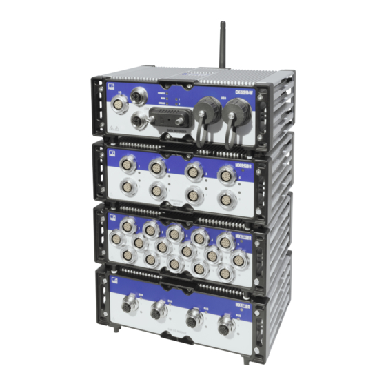
The SomatXR Rugged DAQ series consists of the following modules: MX840B-R universal module: Up to eight (8) universal inputs for connecting more than 16 transducer technologies including one connector compatible with CAN inputs. - Page 10 IEEE1588 PTPv2 transparent clock time synchronization. Five ports provide Power over Ethernet (PoE) to support cameras and other low power Ethernet based data sources. NOTE Details about the EX23-R can be found in the separate CX23-R and EX23-R user manual. A04089_07_E00_02 HBM: public MX Modules...
-
Page 11: Module Transducer Overview
● ● 60 V only 10 V only Current-fed piezoelectric † † † ● ● ● transducer (IEPE, ICP®) Current, 20 mA ● ● ● Resistance or resistance- ● ● based measurements MX Modules A04089_07_E00_02 HBM: public... - Page 12 Use quarter bridge adapter 1-SCM-R-SG1000-2, 1-SCM-R-SG120-2 or 1-SCM-R-SG350-2. Optional: ODU 14-pin to BNC adapter 1-KAB430-0.3. Use thermocouple adapter 1-SCM-R-TCK-2 for K- § type, 1-SCM-R-TCE-2 for E-type, 1-SCM-R-TCT-2 for T-type and 1-SCM-R-TCJ-2 for J-type. Including support for CCP/XCP-on-CAN (not in combination with CX23-R). A04089_07_E00_02 HBM: public MX Modules...
-
Page 13: About The Documentation
SomatXR series offer additional functions. In principle, they can be synchronized using the FireWire or Ethernet-based PTPv2 protocol (IEEE1588). Furthermore, decimal data rates are available in addition to the "Classic HBM Data Rates". Each MX module has a similar back panel with a power connector, two FireWire connectors, and one Ethernet connector. - Page 14 Configurable active digital filter (Bessel, Butterworth or Linear Phase) Configurable scaling (can also be saved in TEDS) Sensors assigned using the sensor database can be calibrated via the channel and written back into the sensor database. A04089_07_E00_02 HBM: public MX Modules...
-
Page 15: Setting Up A System
Older computers require the use of an Ethernet crossover cable. Newer computers have Ethernet interfaces with autocrossing functions. SomatXR MX modules can be used as standalone devices or in a network for centralized control, data synchronization and shared voltage supply through MX Modules A04089_07_E00_02 HBM: public... -
Page 16: Mechanical Fixing Of Modules
Module synchronization. Finally, connect the desired sensors. For guidelines on connecting transducers, see Connecting transducers. 2.2 Mechanical fixing of modules See www.hbm.com for information about devices available for mounting SomatXR rugged modules and accessories. Order No. Item Description 1-CASELINK Installation parts... -
Page 17: Caselinks (1-Caselink Or 1-Caselink-Rug-2)
Use 1-CASEMOUNT3-2 to mount three modules Set screws (M5) and flat screws are included to secure the caselinks and brackets on the modules. See the data sheets at www.hbm.com for more information. NOTE HBM recommends mounting modules individually in high vibration environments. - Page 18 3. Move the caselink in the module slots to align the hole in the bracket (A) with the tapped hole in the mounting surface. 4. Tighten the two (2) M5 set screws (C) in each caselink. Tighten the two (2) M6 screws (E) holding the brackets on the mounting surface. A04089_07_E00_02 HBM: public MX Modules...
- Page 19 Apply serviceable threadlock to M6 screws (B) and install them through the three (3) holes in each bracket (F or G) and into the tapped holes. Tighten the screws to 6.1 N-m (54 in-lbs) torque. MX Modules A04089_07_E00_02 HBM: public...
-
Page 20: Universal Mounting Bracket (1-Casemount-Umb-2)
2.2.3 Universal mounting bracket (1-CASEMOUNT-UMB-2) This bracket can be used in conjunction with the 1-CASEMOUNT2-2 or 1- CASEMOUNT3-2 kits. See the data sheet at www.hbm.com for more information. This universal mounting bracket supports a variety of commercial products that may not meet the vibration specs of the system. - Page 21 4. 1-UPX002-2 and ACKSYS WLg-xROAD/N or /NP or 1-EGPS-5HZ-2 or Axis camera 5. Axis camera and L-Com BT-CAT6P1HP-48W 6. L-Com BT-CAT6P1HP-48W and PoE Power injector power supply (Axis camera mounted separately) Example of Accessory Mounting: Installing a UPX series Uninterruptible Power Supply MX Modules A04089_07_E00_02 HBM: public...
-
Page 22: Power Considerations
For example, in the case of voltage supply by battery, wrap the power supply cable (1-KAB294-W-5) around the included inductive coil four times as pictured below. NOTE This applies to MX modules only and not to the supply of CX23-R or EX23-R modules. A04089_07_E00_02 HBM: public MX Modules... -
Page 23: Connecting A Single Module To A Host Pc
It is recommended to install an uninterruptible power supply (UPS) in vehicles with battery operation between the battery and module to compensate for voltage drops during start procedures. HBM offers the 1-UPX002-2 which can provide uninterruptible power for SomatXR modules. -
Page 24: Connecting Multiple Modules To A Host Pc
Multiple FireWire connection (without CX27C-R or MX471C-R) Data is transferred, modules are synchronized in timing and voltage is supplied via the FireWire connections. A maximum of 12 modules can be connected in series with each other. A04089_07_E00_02 HBM: public MX Modules... - Page 25 Depending on the connection situation, 1 to 2 hops are counted in one hub. To count the total number of hops, the longest chain to the data sink must be counted (worst case). MX Modules A04089_07_E00_02 HBM: public...
- Page 26 Multiple FireWire connection (with CX27C-R or MX471C-R) Data is transferred, modules are synchronized in timing and voltage is supplied via the FireWire connections. A maximum of 12 modules can be connected in series A04089_07_E00_02 HBM: public MX Modules...
- Page 27 (max. 1.5 A through FireWire; for power consumption of one module see specifications in data sheet). The advantage of this connection structure is the other modules remain active if one Ethernet cable is broken. MX Modules A04089_07_E00_02 HBM: public...
-
Page 28: Module Synchronization
LED shows orange. Time stamps are appended to the measured values in the following format: Basis: 1.1.2000 Time stamp: 64 bit 32 bit seconds 32 bit fractions of a second A04089_07_E00_02 HBM: public MX Modules... - Page 29 Synchronization via Ethernet PTP Each SomatXR module can accurately and reliably synchronize its internal clock using PTPv2 synchronization (IEEE1588: 2008). This is achieved using multiple Ethernet connection through a PTPv2 capable Ethernet switch (e.g., EX23-R). MX Modules A04089_07_E00_02 HBM: public...
- Page 30 It is possible to achieve accuracies of 1 ms or higher depending on the utilization of the network and whether a dedicated NTP master is being used. An NTP software package is included in the HBM software catman®EASY to run an NTP master on the PC.
- Page 31 NTP or PTP master must be used for synchronization. This is also a requirement if the MX modules are a long distance away from one another and a FireWire connection would be too complex. MX Modules A04089_07_E00_02 HBM: public...
-
Page 32: Connecting Transducers
(EME), has become increasingly important over the years. According to the HBM Greenline shielding concept, the measuring chain is completely enclosed by a Faraday cage by appropriate routing of the cable shield. The cable shield is extensively connected with the transducer housing and is routed via the conductive plug to the amplifier housing. -
Page 33: Teds
(or shielding) are designed to be physically separate in the HBM devices. The mains earth connector or a separate earth potential lead should serve as the earth connection as is the case for example regarding potential compensation in buildings. - Page 34 NOTE If using a TEDS calibration table for nonlinear transducer scaling, make sure that the TEDS chip is written by the HBM TEDS Editor version 3.4.0.6 or later; catman® version 3.4.1 or later; or QuantumX/MX Assistant version 2.6.R1 or later.
-
Page 35: Digitalization And Signal Path
(TEDS - Transducer Electronic Data Sheet). The amplifier communicates with this EEPROM via the serial 1-wire interface, reads the data sheet and makes the corresponding amplifier settings. HBM recommends the TEDS chip (1-wire® EEPROM) DS24B33 from Maxim. HBM offers a package with 10 TEDS (1-TEDS-PAK). 2.8 Digitalization and signal path Each SomatXR measurement channel generates two signals. -
Page 36: Controlling The System
HBM website (www.hbm.com/daq-support). 3.3.1 HBM Device Manager The HBM Device Manager is a tool that can list all SomatXR, QuantumX and PMX modules found on the network. This function is also included with the MX Assistant. 3.3.2 MX Assistant... -
Page 37: Catman
Generate new signals through mathematical functions (peak value, effective value, addition and multiplication and rotation) 3.3.3 catman® The HBM catman® PC software is optimally suited for the following tasks: Setting the communication and measurement channels (integrated TEDS Editor and extendable sensor database) -
Page 38: Mx Module Programming Interface (Api)
C#. The library includes functions such as communication connection, configuration of inputs and outputs, starting and stopping data acquisition and troubleshooting. Find more information about the HBM common API at www.hbm.com/daq-support. Application-based examples and practice-oriented documentation enable a quick start. -
Page 39: Modules
4 Modules 4 Modules 4.1 MX840B-R universal module Up to eight (8) universal inputs can be connected to the MX840B-R module compatible with more than 16 transducer technologies. Transducer MX840B-R Wiring diagram Strain gage, full bridge ● six-wire configuration Strain gage, half bridge ●... - Page 40 The following table gives the descriptions for all LED states. System LED Description Green System is error free System error Orange System is not ready; boot procedure is running Orange flashing System is not ready; download is active A04089_07_E00_02 HBM: public MX Modules...
- Page 41 Manual configuration; ignore flashing, TEDS then green No sensor connected; channel CAN bus error; CAN error (incorrect parameterization, interface in Bus OFF state; connection error, invalid TEDS CAN data cannot be data) received or processed MX Modules A04089_07_E00_02 HBM: public...
- Page 42 4 Modules MX840B-R pin assignments Connect sensors via the 14-pin ODU MINI-SNAP connectors. Wire Color Connector Connection (1-KAB183 or 1-KAB184) Excitation (-) Black Zeroing pulse (-) Excitation (+) Blue Zeroing pulse (+) Voltage input 10 V (+), 60 V (+)
-
Page 43: Mx1615B-R Bridge Module (Strain Gage Amplifier)
1200 Hz (AC) square wave carrier frequency with an amplitude of 0.5, 1, 2.5 or 5 volts. The measurement channels are electrically isolated from the power supply and the interfaces. When TEDS or T-ID is used, the measurement channel is automatically parameterized after connection. Status LED MX Modules A04089_07_E00_02 HBM: public... - Page 44 NOTE Connection between pins 1 and 11 is necessary for all MX1615B-R transducers. Note that the sensor connector must have a connection between pins 4 and 5 for compatibility with other MX modules. A04089_07_E00_02 HBM: public MX Modules...
-
Page 45: Mx1601B-R Standard Module (Universal Amplifier)
The following table gives the descriptions for all LED states. System LED Description Green System is error free System error Orange System is not ready; boot procedure is running Orange flashing System is not ready; download is active MX Modules A04089_07_E00_02 HBM: public... - Page 46 Channels 9 through 16 output the supply voltage (10 ... 30 V) minus approximately one volt. A maximum current of 30 mA per channel or 75 mA total can be consumed. The current limitation switches the transducer excitation off if current consumption is higher. A04089_07_E00_02 HBM: public MX Modules...
-
Page 47: Mx1609Kb-R Thermocouple Amplifier
(LED flashes for 5 seconds) Orange Transducer identification/sensor scaling is running No sensor connected Channel error (incorrectly parameterized, connection error, invalid TEDS data) Overload of sensor supply Thermocouple with TEDS functionality (RFID) Measuring point identification MX Modules A04089_07_E00_02 HBM: public... - Page 48 Conditions for using RFID chips for measuring point identification All channels can read/write via RFID The neighboring channel must not be occupied during writing Maximum distance chip to housing: 1 mm For self-assembly: check position of chip on plug A04089_07_E00_02 HBM: public MX Modules...
-
Page 49: Mx1609Tb-R Thermocouple Amplifier
(LED flashes for 5 seconds) Orange Transducer identification/sensor scaling is running No sensor connected Channel error (incorrectly parameterized, connection error, invalid TEDS data) Overload of sensor supply Thermocouple with TEDS functionality (RFID) Measuring point identification MX Modules A04089_07_E00_02 HBM: public... - Page 50 Conditions for using RFID chips for measuring point identification All channels can read/write via RFID The neighboring channel must not be occupied during writing Maximum distance chip to housing: 1 mm For self-assembly: check position of chip on plug A04089_07_E00_02 HBM: public MX Modules...
-
Page 51: Mx411B-R Highly Dynamic Universal Module
Use ODU 14-pin to BNC adapter 1-KAB430-0.3. The measurement channels are electrically isolated from each other and from the power supply. When using the adjustable transducer excitation, electrical isolation from the supply voltage is not required. MX Modules A04089_07_E00_02 HBM: public... - Page 52 Connection is newly assigned; transducer identification is running Green flashing, TEDS data is being read then green Orange Manual configuration; ignore TEDS flashing, then green No sensor connected; channel error (incorrect parametization, connection error, invalid TEDS data); overloaded sensor supply A04089_07_E00_02 HBM: public MX Modules...
- Page 53 Green/Black Shield Shield NOTE Connection between pins 4 and 5 is necessary for all transducers. Note that the sensor connector must have a connection between pins 1 and 11 for compatibility with the MX1615B-R module. MX Modules A04089_07_E00_02 HBM: public...
-
Page 54: Mx460B-R Frequency / Counter Module
Always check encoder data sheet for maximum supply voltage. Supplying a sensor supply of 12 volts to a 5-volt encoder may damage it. When TEDS or T-ID is used, the measurement channel is automatically parameterized after connection. A04089_07_E00_02 HBM: public MX Modules... - Page 55 Flashing green (5 seconds), TEDS data being read in then green Flashing orange (5 Manual configuration ongoing (ignore TEDS) seconds), then green System error General rule: Brief flashing, TEDS identified (green: is used, orange: is not used). MX Modules A04089_07_E00_02 HBM: public...
- Page 56 Green/Black Shield Shield NOTE Connection between pins 4 and 5 is necessary for all transducers. Note that the sensor connector must have a connection between pins 1 and 11 for compatibility with the MX1615B-R module. A04089_07_E00_02 HBM: public MX Modules...
-
Page 57: Mx471-R Modules
The following tables give the descriptions for all LED states. System LED Description Green System is error free Orange System is not ready; boot procedure is running Orange flashing System is not ready; download is active System error; faulty synchronization MX Modules A04089_07_E00_02 HBM: public... - Page 58 White CAN_L (dominant low) Blue NOTE According to EMC requirements, Pin 1 can be connected to the shield of the CAN cable. The integration of the module MX471B-R in the potential equalization is highly recommended. A04089_07_E00_02 HBM: public MX Modules...
-
Page 59: Mx471C-R Can / Can Fd Module
The following tables give the descriptions for all LED states. System LED Description Green System is error free Orange System is not ready; boot procedure is running Orange flashing System is not ready; download is active System error; faulty synchronization MX Modules A04089_07_E00_02 HBM: public... - Page 60 According to EMC requirements, Pin 1 can be connected to the shield of the CAN cable. The integration of the module MX471C-R in the potential equalization is highly recommended. NOTE Details about CAN and CAN FD can be found in the separate QuantumX / SomatXR CAN manual. A04089_07_E00_02 HBM: public MX Modules...
-
Page 61: Mx590B-R Pressure Acquisition Module
-1 ... +2.5 bar relative Blue Brown -1 ... +4 bar relative Blue -1 ... + 10 bar relative Blue Yellow -1 ... +16 bar relative Orange Orange 0 ... +25 bar relative Brown Brown Empty (blank plate) MX Modules A04089_07_E00_02 HBM: public... - Page 62 Fatal hardware error. The module must be sent to HBM for recovery. Red flashing Pressure transmitter defect. The module must be sent to HBM for transmitter recovery. Limit exceeded. If TEDS is needed: no TEDS has been detected yet. Orange Preparation of the channel is carried out.
- Page 63 4. Connect the coupling to the corresponding channel. The Channel LED will flash. 5. Select "open TEDS in HBM TEDS Editor" from the TEDS context-menu. 6. Once the TEDS chip content is available to the TEDS Editor, set "Maximum pressure", "Pressure type" and "Channel name" to your desired values.
-
Page 64: Inputs
3-wire only 3-wire only Use quarter bridge adapter 1-SCM-R-SG1000-2, 1-SCM-R-SG120-2 or 1-SCM-R-SG350-2. Full-bridge strain gage NOTE For full four-wire bridge configurations, a connection between the sense lead and excitation lines must be made in the connector. A04089_07_E00_02 HBM: public MX Modules... - Page 65 5 Inputs Half-bridge strain gage NOTE For half three-wire bridge configurations, a connection between the sense lead and excitation lines must be made in the connector. Quarter-bridge strain gages MX Modules A04089_07_E00_02 HBM: public...
- Page 66 5 Inputs A04089_07_E00_02 HBM: public MX Modules...
- Page 67 5 Inputs MX Modules A04089_07_E00_02 HBM: public...
-
Page 68: Inductive Transducers
5 Inputs 5.2 Inductive transducers Transducer MX840B-R MX411B-R ● ● Inductive full bridge ● ● Inductive half bridge LVDT ● (linear variable differential transformer) Inductive full-bridge A04089_07_E00_02 HBM: public MX Modules... - Page 69 5 Inputs Inductive half-bridge MX Modules A04089_07_E00_02 HBM: public...
- Page 70 5 Inputs Linear variable differential transformer (LVDT) A04089_07_E00_02 HBM: public MX Modules...
-
Page 71: Piezoresistive Transducers
5 Inputs 5.3 Piezoresistive transducers Transducer MX840B-R MX411B-R ● ● Piezoresistive transducer MX Modules A04089_07_E00_02 HBM: public... -
Page 72: Potentiometric Transducers
5 Inputs 5.4 Potentiometric transducers Transducer MX840B-R MX1615B-R ● ● Potentiometric transducer A04089_07_E00_02 HBM: public MX Modules... - Page 73 5 Inputs MX Modules A04089_07_E00_02 HBM: public...
-
Page 74: Voltage Sources
1 and 11 is necessary for compatibility with the MX1615B-R module. A connection between pins 4 and 5 is necessary for compatibility with all other MX modules. The MX1615B-R module does not provide an adjustable sensor supply. A04089_07_E00_02 HBM: public MX Modules... -
Page 75: Current-Fed Piezoelectric Transducers (Iepe, Icp®)
Transducer MX840B-R MX1601B-R MX411B-R Current-fed piezoelectric transducer † † † ● ● ● (IEPE, ICP®) † Use ODU 14-pin to BNC adapter 1-KAB430-0.3. NOTE IEPE transducers with TEDS version 1.0 are supported. MX Modules A04089_07_E00_02 HBM: public... -
Page 76: Current Sources
5 Inputs 5.7 Current sources Transducer MX840B-R MX1601B-R MX411B-R ● ● ● Current, 20 mA 20 mA DC Current Source NOTE Maximum current is ±30 mA. A04089_07_E00_02 HBM: public MX Modules... - Page 77 5 Inputs 20 mA Current-fed DC Current Source NOTE Maximum current is ±30 mA. NOTE The sensor supply must be connected in series. This, however, terminates the electrical isolation to the module supply. MX Modules A04089_07_E00_02 HBM: public...
-
Page 78: Resistance-Based Measurements
5 Inputs 5.8 Resistance-based measurements Transducer MX840B-R MX1615B-R ● ● Resistance or resistance-based measurements ● Resistance thermometer (RTD), ● PT100 or PT1000 PT100 only Resistance A04089_07_E00_02 HBM: public MX Modules... - Page 79 5 Inputs Resistance Thermometer (RTD) MX Modules A04089_07_E00_02 HBM: public...
-
Page 80: Thermocouples
5 Inputs 5.9 Thermocouples Transducer MX840B-R MX1609KB-R MX1609TB-R ● ● ‡ Thermocouple ● K-type only T-type only ‡ Use thermocouple adapter 1-SCM-R-TCK-2 for K-type, 1-SCM-R-TCE-2 for E-type, 1-SCM-R-TCT-2 for T-type and 1-SCM-R-TCJ-2 for J- type. A04089_07_E00_02 HBM: public MX Modules... - Page 81 5 Inputs MX Modules A04089_07_E00_02 HBM: public...
-
Page 82: Digital Timer Inputs
MX460B-R ● Frequency / pulse counter ● (timer, TTL) connectors 5-8 ● ● Incremental encoder (timer, TTL) connectors 5-8 ● ● Torque / speed connectors 5-8 ● SSI protocol connectors 5-8 Frequency / pulse counter A04089_07_E00_02 HBM: public MX Modules... - Page 83 5 Inputs MX Modules A04089_07_E00_02 HBM: public...
- Page 84 5 Inputs A04089_07_E00_02 HBM: public MX Modules...
- Page 85 5 Inputs Incremental encoder MX Modules A04089_07_E00_02 HBM: public...
- Page 86 5 Inputs A04089_07_E00_02 HBM: public MX Modules...
- Page 87 5 Inputs Torque / Speed (HBM torque transducers) MX Modules A04089_07_E00_02 HBM: public...
- Page 88 5 Inputs A04089_07_E00_02 HBM: public MX Modules...
- Page 89 5 Inputs Absolute value encoder (SSI protocol) MX Modules A04089_07_E00_02 HBM: public...
-
Page 90: Passive Inductive Encoder
5 Inputs 5.11 Passive inductive encoder Transducer MX460B-R ● Passive inductive encoder A04089_07_E00_02 HBM: public MX Modules... -
Page 91: Pulse Width, Pulse Duration, Period Duration (Pwm)
5 Inputs 5.12 Pulse width, pulse duration, period duration (PWM) Transducer MX460B-R ● PWM - Pulse width, pulse duration, period duration MX Modules A04089_07_E00_02 HBM: public... - Page 92 5 Inputs A04089_07_E00_02 HBM: public MX Modules...
-
Page 93: Can Devices
To ensure normal operation, the CAN bus needs to be terminated at both ends using appropriate termination resistors. The MX471B-R, MX471C-R and MX840B-R provide internal completion resistors between CAN H and CAN L that can be enabled or disabled individually with software. - Page 94 5 Inputs A04089_07_E00_02 HBM: public MX Modules...
-
Page 95: Direct Pressure Sensors
5 Inputs 5.14 Direct pressure sensors Transducer MX590B-R ● Absolute pressure (gas/fluid) sensor ● Relative pressure (gas/fluid) sensor NOTE: Differential pressure (gas/fluid) sensors are not supported. MX Modules A04089_07_E00_02 HBM: public... -
Page 96: Crank Wheel Sensors
5 Inputs 5.15 Crank wheel sensors Transducer MX460B-R ● Crank wheel sensor A04089_07_E00_02 HBM: public MX Modules... - Page 97 5 Inputs MX Modules A04089_07_E00_02 HBM: public...
-
Page 98: Outputs
Outputs Outputs 6.1 Output measurement signals to CAN bus 6.1.1 MX840B-R MX840B-R universal module allows channels 2-8 to output to the CAN bus (channel 1). This mode is configured entirely in the Assistant. 6.1.2 MX471B-R / MX471C-R Both modules MX471B-R and MX471C-R allow measurement signals, or the signal calculated in real time, to be output to the CAN bus. -
Page 99: Output Signals In Real Time
(for example, an acceleration sensor with 100 kS/sec) and deactivated filter for analysis while the second signal can have a lower data rate (for example, 5 kS/sec) and be output via EtherCAT® or PROFINET. A04089_07_E00_02 HBM: public MX Modules... -
Page 100: Revision History
7 Revision History Version Date Notes 08/2014 Initial revision 02/2015 CX23-R and EX23-R 10/2015 MX840B-R, MX411B-R and MX471B-R modules 10/2015 Minor updates 11/2015 Electromagnetic conformity 04/2016 Sensor adapters, UPX-002, outputs 06/2018 Mechanical fixing of modules, KAB430 IEPE adapter pinout corrections, addition of... - Page 101 Asia-Pacific HBM China 106 Heng Shan Road Suzhou 215009 Jiangsu, China Tel: +86 512 682 47776 • Email: hbmchina@hbm.com.cn Europe, Middle East and Africa HBM GmbH Im Tiefen See 45 64293 Darmstadt, Germany Tel: +49 6151 8030 • Email: info@hbm.com...
Need help?
Do you have a question about the MX840B-R and is the answer not in the manual?
Questions and answers