HBM QuantumX Operating Manual
Hide thumbs
Also See for QuantumX:
- Quick start manual (200 pages) ,
- Operating manual (152 pages) ,
- Operating manual (88 pages)
Table of Contents
Advertisement
Quick Links
Advertisement
Table of Contents

Related Manuals for HBM QuantumX


Summary of Contents for HBM QuantumX
- Page 1 Operating Manual English QuantumX...
- Page 2 Tel. +49 6151 803-0 Fax +49 6151 803-9100 info@hbkworld.com www.hbm.com Mat.: DVS: A03031_24_E00_01 HBM: public 10.2021 E Hottinger Brüel & Kjaer GmbH Subject to modifications. All product descriptions are for general information only. They are not to be understood as a guarantee of quality or...
-
Page 3: Table Of Contents
..........About the QuantumX documentation . - Page 4 7.2.3 Multiple Ethernet connection and FireWire synchronization ..7.2.4 Connecting one or more QuantumX modules to the PC ..7.2.5 Firmware update via Ethernet ....... .
- Page 5 Electrical voltage 100 mV ........QuantumX A03031_24_E00_01 HBM: public...
- Page 6 ......... QuantumX A03031_24_E00_01 HBM: public...
- Page 7 ..........QuantumX A03031_24_E00_01 HBM: public...
-
Page 8: Safety Instructions
This can be done, for example, by mechanical interlocking, error signaling, limit value switches, etc. Notice The module must not be connected directly to a power supply system. The supply voltage must be 10 V … 30 V (DC). QuantumX A03031_24_E00_01 HBM: public... - Page 9 For all modules: S Do not expose the modules to direct sunlight. S Please observe the permissible maximum ambient temperatures stated in the specifications. S Ensure there is adequate ventilation for installation in the BPX001 back plane. QuantumX A03031_24_E00_01 HBM: public...
- Page 10 Important instructions for your safety are specifically identified. It is essential to follow these instructions in order to prevent accidents and damage to property. Safety instructions are structured as follows: WARNING Type of danger Consequences of non-compliance Averting the danger QuantumX A03031_24_E00_01 HBM: public...
- Page 11 The supply connection, as well as the signal and sensor leads, must be installed in such a way that electromagnetic interference does not adversely affect device functionality (HBM recommendation: "Greenline shielding design", downloadable from the Internet at http://www.hbm.com/Greenline). Automation equipment and devices must be covered over in such a way that adequate protection or locking against unintentional actuation is provided (e.g.
- Page 12 In particular, any repair or soldering work on motherboards (exchanging components) is prohibited. When exchanging complete modules, use only original parts from HBM. The module is delivered from the factory with a fixed hardware and software configuration. Changes can only be made within the possibilities documented in the manuals.
- Page 13 It is also essential to comply with the legal and safety requirements for the application concerned during use. The same applies to the use of accessories. QuantumX A03031_24_E00_01 HBM: public...
-
Page 14: Electro Magnetic Conformity
Emissions: Class A Immunity: Industrial environment The QuantumX series and its modules are intended for use in an industrial environment. When used in residential or commercial environments, additional arrangements may be required to limit electro-magnetic emissions. - Page 15 Electro magnetic conformity ODU plug When the NTX001 power supply from HBM is used, the system complies with Emissions: Class B without the necessity to carry out the meaasure described above. QuantumX A03031_24_E00_01 HBM: public...
-
Page 16: Markings Used
Sampling rate, 500 Bold text in italics indicates inputs and input fields in the user interfaces. Emphasis Italics are used to emphasize and highlight text and See … identify references to sections, diagrams, or external documents and files. QuantumX A03031_24_E00_01 HBM: public... -
Page 17: Symbols On The Device
(Japan). The EMC of the power supply unit has been tested in accordance with IEC61326. UKCA marking With the UKCA marking the manufacturer demonstrates that the product complies with the requirements of the relevant UK regulations. QuantumX A03031_24_E00_01 HBM: public... - Page 18 Statutory waste disposal mark In accordance with national and local environmental pro tection and material recovery and recycling regulations, old devices that can no longer be used must be disposed of separately and not with normal household garbage. QuantumX A03031_24_E00_01 HBM: public...
- Page 19 For details please check the MXFS user manual avail able from www.hbm.com Connection for functional earth If necessary, integrate the module into your functional grounding via this connection, so that interference cur rents can be surcharged and interference signal injection prevented. QuantumX A03031_24_E00_01 HBM: public...
-
Page 20: Introduction
Introduction Introduction About the QuantumX documentation The QuantumX family documentation consists of S a printed quick-start guide for initial startup and safety instructions S the data sheets in PDF format S This operating manual in PDF format ℑ 1) S the operating manual for the EtherCAT®... -
Page 21: The Quantumx Family
The QuantumX family The QuantumX family is a modular measurement system for universal applica tions. The modules can be individually combined and intelligently connected according to the measurement task. Distributed operation makes it possible to position individual modules close to the measuring points, resulting in short sensor lines. - Page 22 The module and entire production have been certified by VDE, and stand for maximum safety when working with dangerous voltages. Notice When using the modules MX403B or MX809B, please refer to the separate operating manual, document number A 3757. QuantumX A03031_24_E00_01 HBM: public...
- Page 23 S CX27C EtherCAT®/PROFINET IRT, xCP-on-Ethernet and Ethernet Gateway The module is used to connect QuantumX modules to the EtherCAT or PROFINET IRT fieldbus, or via XCP-on-Ethernet to MCD software such as CANape, INCA, ATI Vision, or via Ethernet to a PC running the catman software.
- Page 24 S Configurable sampling rate S Configurable digital filter (Bessel, Butterworth) S configurable scaling Sensors assigned using the sensor database can be calibrated via the channel and written back into the sensor database. TEDS = Transducer Electronic Data Sheet QuantumX A03031_24_E00_01 HBM: public...
-
Page 25: Module Overview/Transducer Technologies
Introduction Module overview/transducer technologies See data sheets for precise technical specifications. The pin assignments can be found in the following chapters. QuantumX A03031_24_E00_01 HBM: public... -
Page 26: Digitalization And Signal Path
Digitalization and signal path Data rate QuantumX measurement modules with the suffix B, like the MX840B, for instance, have decimal data rates such as 600, 1200, ..19,200 S/sec avail able, in addition to classic data rates such as 500, 1000, ..100,000 S/sec. -
Page 27: Synchronization
If measurement signals need to be referenced over time with each other for processing and analysis, they must be recorded synchronously. All QuantumX modules can be synchronized among themselves. This ensures simultaneous measurement on all channels. All the analog-digital converter rates, measuring rates and bridge excitation voltages are therefore also syn... - Page 28 CAT®. The time is distributed to all EtherCAT® nodes in an EtherCAT® group. The CX27C module can be synchronized to the EtherCAT® time. This will mean that all the QuantumX module clocks are synchronized to this time. Synchronization via an NTP server Each QuantumX module can synchronize its internal clock with an NTP server.
- Page 29 Modules located close together should be synchronized via IEEE1394b FireWire. If the synchronization source for a module is changed to NTP, the system must be restarted once. The HBM catman®EASY software includes an NTP soft ware package. Parameter: S IP address of the NTP server S Threshold in μs below which the time deviation to NTP time is tolerated...
- Page 30 2 min during restart Synchroniza Auto Auto oder External Syn External External tion 1 QuantumX Grandmas cMaster , SyncMaster IRIG-B master module ter‐ e.g. PC master Clock Voltage sup < 1.5 A, looped...
- Page 31 (IEEE1394b FireWire to the modules) Auto Auto Auto Time base: NTP server Ethernet Synchronizing via Ethernet / NTP (without IEEE1394b FireWire) Time base: NTP server Ethernet switch CX27 or the module with the highest serial number QuantumX A03031_24_E00_01 HBM: public...
- Page 32 The filter runtimes are shown in the respective data sheet. After booting and successful synchronization, the system LED is lit green. If synchronization is disturbed, or not yet established, the system LED is lit orange. Example: MX840B QuantumX A03031_24_E00_01 HBM: public...
- Page 33 There are several synchronization methods to choose from (also see Fig. 4.1 page 32): S IEEE1394b FireWire S Ethernet PTPv2 (Precision Time Protocol), applies only to B and C modules such as MX840B, CX27C, MX471C, ..S EtherCAT ® (via gateway module CX27C) QuantumX A03031_24_E00_01 HBM: public...
-
Page 34: Software
Software Software QuantumX is an "open" data acquisition system, and can be integrated into a great many operating, analysis and automation software packages. The following powerful packages are available to download: S MX Assistant: a modern and free device or system assistant that supports all the module functions ®... -
Page 35: Catman®Ap
S Write/read sensor and calibration data on TEDS S Add user-defined sensor data sheets, import CANdb (*.dbc) catman®AP The HBM "catman®AP" software is optimally suited for the following tasks: S Setting the communication and measurement channels (integrated TEDS editor and extendable sensor database) S Configuration of measurement or test tasks (channels, sampling rates, trig... - Page 36 S EasyScript is based on the current VBA standard (Visual Basic for Applica tions) and allows users to write their own scripts for individual measurement tasks S EasyMath allows mathematical postprocess analysis and export of mea surement data QuantumX A03031_24_E00_01 HBM: public...
-
Page 37: Labview® Driver / Library
The HBM LabVIEW driver is based on the HBM Common API. The installa tion includes some examples and extensive help. -
Page 38: Other Drivers
Software Other drivers QuantumX is an open data acquisition system and therefore has been inte grated into many software packages. Here are some examples: S DIAdem S CANape S DASYLab S MATLAB S Mlab S InNova Firmware update via Ethernet You can easily check the firmware status of the modules and update them ®... -
Page 39: Mechanical
These indicate which degree of protection a housing offers against contact or foreign bodies (first digit) and moisture (second digit). QuantumX modules are in a housing with IP20 as degree of protection. Code Degree of protection against... -
Page 40: Mounting Case Clips On Modules
Case protection MX840 housing Cover Fig. 6.1 Amplifier MX840 with case protection The mounting of the housing clips shown in the following pictures must be implemented on both sides of the housing. QuantumX A03031_24_E00_01 HBM: public... - Page 41 Mechanical 2.5 a.f. Fig. 6.2 Removing the case protection Cover Fig. 6.3 Removing the cover QuantumX A03031_24_E00_01 HBM: public...
- Page 42 Mechanical Case clip 2.5 a.f. Fig. 6.4 Mounting the case clip CASECLIP 2.5 a.f. Fig. 6.5 Mounting the case protection CASEPROT QuantumX A03031_24_E00_01 HBM: public...
-
Page 43: Connecting Housings
Mechanical Connecting housings The following pictures show the connection of two housings. Press Fig. 6.6 Unclip the case clip CASECLIP Lever Catch Fig. 6.7 Unclip the lever and catch QuantumX A03031_24_E00_01 HBM: public... - Page 44 Mechanical Fig. 6.8 Close the lever Fig. 6.9 Connected housings QuantumX A03031_24_E00_01 HBM: public...
-
Page 45: Mounting The Housing With Casefit
Mechanical Mounting the housing with CASEFIT A CASEFIT fitting panel can be used for flexible mounting of QuantumX series modules. The modules can be fastened in place with belt tensioners or case clips (CASECLIP). Ø 5.6 Lugs for additional fastening with tension belts Dimensions in mm (1 mm = 0.03937 inches) - Page 46 BPX001 is designed for wall or control cabinet installation and has drill holes for attachment. The BPX002 backplane for rack mounting in a 19” enclosure. The BPX002 backplane is an extension of the BPX001. Slot 9 Slot 1 Fig. 6.11 Example of QuantumX backplane fitting QuantumX A03031_24_E00_01 HBM: public...
-
Page 47: Connection
LEDs 4 x 4 A/T Supply voltage 18 V ... 30 V DC 5 A max. Connector 1-CON-S1010) is included) Grounding Fig. 6.12 BPX001 connections Fuse Protects IEEE1394b FireWire X1 connection IEEE1394b FireWire X2 connection QuantumX A03031_24_E00_01 HBM: public... -
Page 48: Backplane Bpx001
Note the following information when installing one or more backplanes in a con trol cabinet: S When installing in a control cabinet, the temperature limits given in the tech nical data of the backplanes must be complied with QuantumX A03031_24_E00_01 HBM: public... -
Page 49: Backplane Bpx002
S The ventilation slots of the modules must not be covered (by cable ducts, etc.) 6.4.3 Backplane BPX002 214.5 482.6 448.5 Fig. 6.14 Rackmontage BPX002 To use the BMX002 backplane as a desktop enclosure, the 1-BPX002-SIDE accessory can be used. QuantumX A03031_24_E00_01 HBM: public... -
Page 50: Bpx003 Backplane
150 mm). Notice The modules can only be fastened in backplanes in housings with degree of protection IP20 without case protection, case clips or lateral covers. If these are present, remove as shown in section 6. QuantumX A03031_24_E00_01 HBM: public... - Page 51 3. Position the module vertically on the backplane and push it in carefully on the lower guide rail back up to the stop. Upper screwed clamping gland 4,0 a.f. Opening for con nection to Ethernet Guide rails Lower screwed clamping gland Fig. 6.17 Mounting the module QuantumX A03031_24_E00_01 HBM: public...
- Page 52 Mechanical Fig. 6.18 Centering above the connection plug 4. Tighten the lower then the upper screwed clamping gland. Fig. 6.19 Tightening the screwed clamping glands, sequence QuantumX A03031_24_E00_01 HBM: public...
-
Page 53: Backplane With Ethernet Connection
The individual modules can also be connected directly via Ethernet on the back, with maximum sampling rate. In this case, no gateway is required. Fig. 6.20 Connecting a backplane via Ethernet QuantumX A03031_24_E00_01 HBM: public... -
Page 54: System Layout With Several Backplanes
PC or test bench is required in order to connect up to 24 modules. Larger setups must be synchronized via Ethernet PTPv2. QuantumX Gateway: CX27C, MX471C KAB272-2 or -5 8 x MX QuantumX 9 x MX… Max: 24 modules Fig. 6.21 Synchronizing multiple backplanes QuantumX A03031_24_E00_01 HBM: public... -
Page 55: Connecting Individual Quantumx Modules
Connecting individual QuantumX modules Connecting individual QuantumX modules Connecting the supply voltage Connect the modules to a DC voltage of 10 V ... 30 V (24 V typical). The power consumption per device can be found in the following table. - Page 56 Connecting individual QuantumX modules Module Maximum power consumption, including transducer excitation voltage (watts) MX403B MXFS CX22B-W/CX22B CX27C MX878B MX879B If several modules are connected to each other via FireWire for time-synchro nous data acquisition (see Fig. 7.4), the supply voltage can be looped through.
-
Page 57: Connection To Host Pc Or Data Recorder
Connecting individual QuantumX modules Connection to host PC or data recorder 7.2.1 Single Ethernet connection 10 V ... 30 V DC X104 1-NTX001 or 1-KAB271-3 TCP/IP, 100 Mbps KAB293-2 X100 Fig. 7.2 Single Ethernet connection QuantumX A03031_24_E00_01 HBM: public... -
Page 58: Multiple Ethernet Connection With Ptp Synchronization
Connecting individual QuantumX modules 7.2.2 Multiple Ethernet connection with PTP synchronization 10 V ... 10 V ... 10 V ... 30 V DC 30 V DC 30 V DC Patch cable PTPv2‐Switch Patch cable Ethernet Fig. 7.3 Multiple connection via Ethernet and synchronization via PTPv2 The modules can be connected to the PC and synchronized via Ethernet PTPv2-compliant switches. -
Page 59: Multiple Ethernet Connection And Firewire Synchronization
(max. 1.5 A through FireWire; for power consumption of the modules, see Chapter 7). 7.2.4 Connecting one or more QuantumX modules to the PC Modules can be connected to a standard PC via Ethernet (up to 100 m) or via EtherCAT. - Page 60 S FireWire adapter addressing (e.g. expressCard/34 or PCIexpress) at the PC or data logger end uses a previously installed Windows device driver from HBM, and cannot be modified. The modules are automatically addressed (plugandplay and USB), and are available immediately.
- Page 61 To configure the IP address of the module: S Activate DHCP/APIPA for automatic configuration. Please set any PC directly connected to QuantumX to DHCP as well. S Manual configuration: Deactivate DHCP and enter the same subnet mask address as used with your PC. Change the IP address of your module so...
- Page 62 Connecting individual QuantumX modules Example: – Setting the IP address manually module side Settings IP address Subnet mask Module before 169.1.1.22 255.255.255.0 PC / notebook 172.21.108.51 255.255.248.0 Module after 172.21.108.1 255.255.248.0 The first three digit groups of the PC and module IP addresses should be the same.
- Page 63 Connecting individual QuantumX modules Automatic configuration Module settings PC settings 172.21.108.1 Module settings 255.255.248.0 Manual configuration PC settings Fig. 7.5 Example of settings for a direct connection QuantumX A03031_24_E00_01 HBM: public...
- Page 64 Connecting individual QuantumX modules Ethernet settings: adjust the IP address of your PC If you want to operate the modules with a fixed, static IP address, you should use the "Alternative Configuration" (fixed IP address and subnet mask, userdefined) in the Ethernet adapter properties under TCP/IP the ”Alternative Configuration”...
- Page 65 Connecting individual QuantumX modules Example: – Setting the IP address manually PC side Settings IP address Subnet mask Module before 169.1.1.22 255.255.255.0 PC / notebook before 172.21.108.51 255.255.248.0 PC / notebook after 169.1.1.1 255.255.255.0 S Confirm twice with “ ”...
-
Page 66: Firmware Update Via Ethernet
Notice Please note that with the Ethernet setting DHCP/APIPA, the DHCP server requires a certain amount of time to assign an IP address to the QuantumX module. After connecting the hardware to the network or PC, wait about 30 seconds before starting CATMAN. Otherwise the device may not be found. - Page 67 If the modules have a firmware version < 2.21, you should install the QuantumX Firmware Updater tool, and use it to bring all the modules up to date. From firmware version >...
-
Page 68: Distributed Setup
Connecting individual QuantumX modules 7.2.6 Distributed setup Fig. 7.6 Example of distributed setup Data is transferred, modules are synchronized in timing and voltage is supplied via the FireWire connections. You can connect a maximum of 12 modules in series with each other. -
Page 69: Layout With Data Recorder Cx22B-W
Connecting individual QuantumX modules 7.2.7 Layout with data recorder CX22B‐W 10 V ... 30 V DC (NTX001, etc.) Connection via Ethernet cable or wireless (WLAN) CX22B-W FireWire connection Fig. 7.7 Layout with CX22‐W 7.2.8 Output measurement signals to CAN bus (MX840B) The MX840B amplifier allows channels 28 to output to the CANbus (chan... -
Page 70: Output Measurement Signals To Can Bus (Mx471C)
Connecting individual QuantumX modules 7.2.9 Output measurement signals to CAN bus (MX471C) The MX471C module allows measurement signals, or the signals calculated in real time, to be output to the CAN Bus. This gateway mode is typically used in test benches or in mobile measuring mode, for connection to a central CANbased data logger. -
Page 71: Output Of Signals With Standardized Voltage In Real Time (Mx878B Or Mx879B)
7.2.10 Output of signals with standardized voltage in real time (MX878B or MX879B) It is very easy to integrate QuantumX via the globally standardized interface of a normalized voltage (+/ 10 V), particularly in a test bench environment. MX878B or MX879B modules for distributed use serve this purpose. These modules also allow onboard different input channel calculations, such as... -
Page 72: Output Signals In Real Time Via Ethercat ® Or Profinet Irt And In Parallel Via Ethernet
PROFINET IRT and in parallel via Ethernet Each source in a QuantumX system is distributed into two signals, to which different data rate and filtering parameters can be assigned. For example, the first signal of an input channel with a high data rate, e.g. -
Page 73: Modules And Transducers
(EMI) and the permissible electromagnetic interference emissions (EME), has become increasingly important over the years. The HBM Greenline shielding design The measuring chain is completely enclosed by a Faraday cage by appropriate routing of the cable shield. The cable shield is extensively connected with the transducer housing and is routed via the conductive plug to the amplifier hous... -
Page 74: Active Transducer Connection
In order to minimize the effect of electromagnetic interference and differences in potential, the signal ground and ground (or shielding) are designed to be physically separate in the HBM devices. The grounded supply connector or a separate ground potential lead should serve as the ground connection, as is the case for potential compensation in buildings, for example. -
Page 75: Teds
TEDS stands for "Transducer Electronic Data Sheet" and refers to the elec tronic data sheet of a transducer or sensor that is stored in a small electronic chip or appropriate module which is permanently connected to the device. QuantumX A03031_24_E00_01 HBM: public... - Page 76 S transducer manufacturer, type, serial number etc. S calibration date, recalibration interval, calibrator's initials, etc. The amplifiers in the QuantumX series are capable of reading the transducer information stored in the data sheet and automatically converting it into ampli fier settings to enable rapid and safe measurement operation.
- Page 77 ("one‐wire circuit") or retrofit TEDS in the transducer connector. S Amplifiers with direct connection of IEPE transducers support TEDS Ver sion 1.0. S A special TEDS module is integrated in some HBM transducers. It can transmit TEDS data via the feedback line of a sensor (patented "zero‐wire circuit").
-
Page 78: Background Calibration / Autoadjustment
Modules and transducers ® HBM recommends the TEDSmodule (1Wire EEPROM) DS24B33 from Dal las Maxim. HBM offers a package with 10 TEDS: order no. :1-TEDS-PAK Bridge 2 Data 3 No function 1-wire EEPROM 1 2 3 (DS24B33) View from below 8.1.4... - Page 79 These channels therefore demonstrate high stability with respect to self-heat ing. Background calibration can be parameterized with the QuantumX Assistant or using catmanEASY®. Background calibration is switched on the default settings. The cyclical calibra...
-
Page 80: Mx840/A/B Universal Amplifier
MX840B connectable transducers Transducer type Connection sockets See page Resistive full bridge 1 ... 8 Resistive half bridge 1 ... 8 Resistive quarter bridge via external 1 ... 8 adapter QuantumX A03031_24_E00_01 HBM: public... - Page 81 1 ... 8 Current-fed piezoelectric transducer ICP® (IEPE, ) via an external ad 1 ... 8 apter Potentiometer 1 ... 8 Ohmic resistance 1 ... 8 Resistance thermometer PT100, 1 ... 8 PT1000 Thermocouple 1 ... 8 QuantumX A03031_24_E00_01 HBM: public...
-
Page 82: Mx840B Pin Assignment
Modules and transducers Transducer type Connection sockets See page Incremental encoder 5 ... 8 from 141 SSI protocol 5 ... 8 Torque/speed (HBM torque trans 5 ... 8 142, 151 ducer) Frequency measurement, pulse 5 ... 8 from 141 counting CAN bus 8.2.1... -
Page 83: Mx840B Status Display
MX840B status display The front panel of the universal amplifier has a system LED and 8 connection LEDs. The system LED indicates the status of the device, the connection LEDs the states of the individual connections. QuantumX A03031_24_E00_01 HBM: public... - Page 84 Flashing orange (5 s), Manual configuration ongoing (ignore TEDS) then green No sensor connected Channel error (incorrectly parameterized, connection error, invalid TEDS data) CAN LEDs Green CAN bus activated, CAN data can be received QuantumX A03031_24_E00_01 HBM: public...
-
Page 85: Mx440B Universal Amplifier
MX440B front view System LED Green Error-free operation Orange System is not ready, boot procedure running Flashing orange Download active, system is not ready Error Connection LEDs All LEDs are orange Boot procedure running (system is not ready) QuantumX A03031_24_E00_01 HBM: public... -
Page 86: Mx410B Highly Dynamic Universal Amplifier
MX410B connectable transducers Transducer type Connection sockets See page Resistive full bridge 1 ... 4 Resistive half bridge 1 ... 4 Resistive quarter bridge via 1 ... 4 adapter QuantumX A03031_24_E00_01 HBM: public... -
Page 87: Mx410B Pin Assignment
So that insertion or removal of a transducer connection can be unmistakably identified, Pin 4 and Pin 9 in the connector plug must be bridged! If this bridge is missing, no measurement values will be recorded at the connection! QuantumX A03031_24_E00_01 HBM: public... - Page 88 Current input "30 mA (+) Voltage input 10 V, IEPE (+) Digital output, for external charge amplifier, etc., 5 V/max. 10 mA The analog output can be tapped via BNC. For configuration instructions see section 10 "Functions and outputs". QuantumX A03031_24_E00_01 HBM: public...
-
Page 89: Mx410B Status Display
Green Error-free operation Flashing green (5s), TEDS data being read in then green Flashing orange (5 s), Manual configuration ongoing (ignore TEDS) then green No sensor connected Channel error (incorrectly parameterized, connection error, invalid TEDS data) QuantumX A03031_24_E00_01 HBM: public... -
Page 90: Mx430B Resistive Full Bridge Measuring Amplifier
15-pin D-SUB-15HD device connectors. All measuring channels are electrically isolated from one another and from the power supply. MX430B connectable transducers Transducer type Connection sockets See page Resistive full bridge 1 ... 4 QuantumX A03031_24_E00_01 HBM: public... -
Page 91: Mx430B Pin Assignment
Measurement signal (+) TEDS (-) Sense lead (-) Sense lead (+) Signal ground Measurement signal (-) Active sensor supply 5 ... 24 V (0 V) Active sensor supply 5 ... 24 V (+) Free Free Digital output QuantumX A03031_24_E00_01 HBM: public... -
Page 92: Mx430B Status Display
Error-free operation Flashing green (5 s), TEDS data being read in then green Flashing orange (5 s), Manual configuration ongoing (ignore TEDS) then green No sensor connected Channel error (incorrectly parameterized, connection error, invalid TEDS data) QuantumX A03031_24_E00_01 HBM: public... -
Page 93: Mx238B Pin Assignment
So that insertion or removal of a transducer connection can be unmistakably identified, Pin 4 and Pin 9 in the connector plug must be bridged! If this bridge is missing, no measurement values will be recorded at the connection! QuantumX A03031_24_E00_01 HBM: public... - Page 94 Measurement signal (+) TEDS (-) Sense lead (-) Sense lead (+) Signal ground Measurement signal (-) Active sensor supply 5 ... 24 V (0 V) Active sensor supply 5 ... 24 V (+) Free Free Digital output QuantumX A03031_24_E00_01 HBM: public...
-
Page 95: Mx238B Status Display
Error-free operation Flashing green (5s), TEDS data being read in then green Flashing orange (5 s), Manual configuration ongoing (ignore TEDS) then green No sensor connected Channel error (incorrectly parameterized, connection error, invalid TEDS data) CAN LEDs QuantumX A03031_24_E00_01 HBM: public... -
Page 96: Mx460B Frequency Amplifier
When using the adjustable transducer excitation, elec trical isolation from the supply voltage of the amplifier is not required. MX460B connectable transducers Transducer type Connection sockets See page Torque/speed (HBM torque 1 ... 4 142, 151 transducer) Frequency measurement, pulse 1 ... 4... -
Page 97: Mx460B Pin Assignment
Active sensor supply 5 ... 24 V (-) Active sensor supply 5 ... 24 V (+) Not in use AC+ (for passive inductive transducers) Digital output, for example to activate a calibration signal for T10F(S) and T40, 5 V/max. 10 mA QuantumX A03031_24_E00_01 HBM: public... -
Page 98: Mx460B Status Display
Flashing orange (5 s), then Manual configuration ongoing (ignore TEDS) green No sensor connected Channel error (incorrectly parameterized, connection error, invalid TEDS data) General rule: Brief flashing → TEDS identified (green: is used, orange: is not used). QuantumX A03031_24_E00_01 HBM: public... -
Page 99: Mx1609Kb And Mx1609Tb Thermocouple Amplifier
MX1609 Thermocouple Type Thermocouple material 1 (+) Thermocouple material 2 (-) Nickel-chrome (color code green) Nickel (color code white) Copper (color code brown) Copper-nickel (color code white) Connection of the thermocouple plug in the miniature design. QuantumX A03031_24_E00_01 HBM: public... -
Page 100: Thermocouple With Teds Functionality (Rfid)
(°C or °F) or thermal calibration data. The data is written to the RFID via the HBM software. The data is read and written via the RFID transponder built into the module. - Page 101 S Maximum distance chip to housing: 1 mm S For self-assembly: Check position of chip on plug Thermocouple plug with integrated RFID chip from HBM RFID chip The chip for measuring point identification is already integrated in the HBM THERMO-MINI. QuantumX A03031_24_E00_01 HBM: public...
-
Page 102: Mx1609 Status Display
Connection newly assigned, transducer identification run ning (calibration) Green Error-free operation ("Ignore TEDS" or "if available" set, channel is manually configured) Flashing green (5s), then Error-free operation ("Use TEDS" or "if available" set green and TEDS data valid) QuantumX A03031_24_E00_01 HBM: public... -
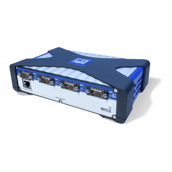
Page 103: Mx471C Can Fd/Can Module
Each node on the MX471C can be parameterized as a receiver and/or a transmitter/gateway. Parameterization as a receiver is described in section 8.9.4. Parameterization as a transmitter is set out in section 9. The online help that comes with the respective software package provides detailed information about parameterization. QuantumX A03031_24_E00_01 HBM: public... -
Page 104: Mx471C Pin Assignment
The configuration of a node is retained after switching the modules off and on. 8.9.2 MX471C pin assignment Fig. 8.14 Pin arrangement of connector plug, view from the solder side Connector SubD 9 to CiA No function CAN Low No function CAN Shield QuantumX A03031_24_E00_01 HBM: public... -
Page 105: Mx471C Status Leds
Bus is error-free and no activity on CAN Yellow flickering Intermittent bus errors (warning) and activity on CAN Constant yellow Intermittent bus errors (warning) and no activity on CAN Red on Bus error, CAN interface in "Bus-OFF" status QuantumX A03031_24_E00_01 HBM: public... -
Page 106: Receiving Can Messages
B) Decoding on the device and in real time. This has the advantage that the signals in the module or in the QuantumX system network are available in real time, and so, for example, incoming signals can be repackaged into other messages and with a different data type, or relayed to other buses or outputs (EtherCAT, PROFINET, xCP-on-Ethernet, voltage output). -
Page 107: Mx1601B Amplifier
MX1601B connectable transducers Transducer type Connection sockets See page Electrical voltage 1 ... 16 130, 131 Electrical current 1 ... 16 Current-fed piezoelectric transducer ICP® (IEPE, ) via an external ad 1 ... 16 apter QuantumX A03031_24_E00_01 HBM: public... - Page 108 Voltage output 10 V (+), 100 mV (+), IEPE (+) Signal ground, TEDS (-) Current input 20 mA (+) TEDS (+) Always connect with Pin 2! (Plug-in detection) Active sensor supply (+) Active sensor supply (-) Housing (shield connection) QuantumX A03031_24_E00_01 HBM: public...
- Page 109 Connection LED System Connection LED Fig. 8.17 MX1601B front view System LED Green Error-free operation Orange System is not ready, boot procedure running Flashing orange Download active, system is not ready QuantumX A03031_24_E00_01 HBM: public...
- Page 110 Manual configuration ongoing (ignore TEDS) then green Amplifier overload, no sensor connected Channel error (incorrectly parameterized, connection error, invalid TEDS data) Flashing red Sensor supply overload General rule: Brief flashing → TEDS identified (green: is used, orange: is not used). QuantumX A03031_24_E00_01 HBM: public...
-
Page 111: Mx1615B/Mx1616B Amplifier
When TEDS or TID is used, the measurement channel is automatically parameterized after connection. MX1615B connectable transducers Transducer type Connection sockets See page 1 … 16 Resistive full bridge Resistive half bridge 1 ... 16 Resistive quarter bridge 1 ... 16 QuantumX A03031_24_E00_01 HBM: public... - Page 112 Pin 4 and Pin 5 in the connector plug must be bridged! This is auto matically so for all bridge transducers. The bridge only needs to be completed for voltage measurements. If this bridge is missing, no measurement values will be recorded at the connection! QuantumX A03031_24_E00_01 HBM: public...
- Page 113 Bridge excitation voltage (-), (TEDS) (-) Sense lead (-) Measurement signal (+), voltage input 10 V / 30 V (+) Measurement signal (-), voltage input 0 V / 10 V (-), bridge excitation voltage (+) for quarter bridges Housing (shield connection) QuantumX A03031_24_E00_01 HBM: public...
- Page 114 Boot procedure running (system is not ready) All LEDs are flashing orange Firmware download active (system is not ready) Orange Connection newly assigned, transducer identification running (calibration) Green Error-free operation Flashing green (5s), then TEDS data being read in green QuantumX A03031_24_E00_01 HBM: public...
- Page 115 Manual configuration ongoing (ignore TEDS) green Amplifier overload, no sensor connected Channel error (incorrectly parameterized, connection error, invalid TEDS data) Flashing red Sensor supply overload General rule: Brief flashing → TEDS identified (green: is used, orange: is not used). QuantumX A03031_24_E00_01 HBM: public...
-
Page 116: Transducer Connection
Sense lead (-) 2 Data 3 No function 1 2 3 1-wire EEPROM (optional) view from below Hsg. = Housing Cable color code: wh= white; bk= black; bu= blue; rd= red; ye = yellow; gn= green; gy= gray QuantumX A03031_24_E00_01 HBM: public... -
Page 117: Full Bridge, Inductive
Sense lead (-) 2 Data 3 No function 1 2 3 1-wire EEPROM (optional) Hsg. = Housing view from below Cable color code: wh= white; bk= black; bu= blue; rd= red; ye = yellow; gn= green; gy= gray QuantumX A03031_24_E00_01 HBM: public... -
Page 118: Full Bridge, Piezoresistive
Measurement signal (+) Excitation (-) Excitation (+) Measurement signal (-) Cable shield Hsg. Sense lead (+) Sense lead (-) 2 Data 3 No function 1 2 3 1-wire EEPROM (optional) view from below Hsg. = Housing QuantumX A03031_24_E00_01 HBM: public... - Page 119 Transducer connection Full bridge with shunt 6 x Cable Resistance -UB/2 Measurement signal (+) Measurement signal (-) Rshunt+ +UB/2 Full bridge Shunt signal only available if 1 and 4 externally connected QuantumX A03031_24_E00_01 HBM: public...
-
Page 120: Half Bridge, Resistive
Sense lead (-) 2 Data 1 2 3 3 No function 1-wire EEPROM (optional) view from below Hsg. = Housing Cable color code: wh= white; bk= black; bu= blue; rd= red; ye= yellow; gn= green; gy= gray QuantumX A03031_24_E00_01 HBM: public... - Page 121 Transducer connection Half bridge with shunt 5 x Cable Resistance -UB/2 Measurement signal (+) Measurement signal (-) Rshunt+ +UB/2 Half bridge Shunt signal only available if 1 and 4 externally connected QuantumX A03031_24_E00_01 HBM: public...
-
Page 122: Half Bridge, Inductive
Sense lead (-) 2 Data 1 2 3 3 No function 1-wire EEPROM (optional) view from below Hsg. = Housing Cable color code: wh= white; bk= black; bu= blue; rd= red; ye = yellow; gn= green; gy= gray QuantumX A03031_24_E00_01 HBM: public... -
Page 123: Quarter Bridge, Resistive
Cable shield Cable color code: wh= white; bk= black; 2 Data bu= blue; rd= red; 1 2 3 ye = yellow; 3 No function gn= green; 1-wire EEPROM (optional) gy= gray Hsg. = Housing view from below QuantumX A03031_24_E00_01 HBM: public... -
Page 124: Quarter Bridge Adapter, Resistive
MX840B, MX440B, MX430B, MX238B, MX410B Available adapters SG with 120 ohms: order number: SCM-SG120 Variations:SCM-SG350, SG1000 1’ Solder pads SG 120 / 350 For technical details see the leaflet entitled QuantumX/SCM-SG120/350/1000. QuantumX A03031_24_E00_01 HBM: public... -
Page 125: Connecting Transducers With Double Shield Technique
This applies for all bridge connections. With cable lengths >50 m, a resistor with half the value of the bridge resistance (RB/2) must be connected in each sense lead of the transducer. QuantumX A03031_24_E00_01 HBM: public... -
Page 126: Potentiometric Transducers
Transducer connection Potentiometric transducers Supported by the following modules: MX840B, MX440A, MX1615B MX1615B Push in Measurement signal (+) Cable shield Hsg. 2 Data 3 No function 1 2 3 1-wire EEPROM (optional) (view from below) QuantumX A03031_24_E00_01 HBM: public... -
Page 127: Lvdt Transducers
Measurement signal (+) Excitation (-) Excitation (+) Measurement signal (-) Hsg. Cable shield Sense lead (+) Sense lead (-) 2 Data 1 2 3 3 No function 1-wire EEPROM (optional) view from below Hsg. = Housing QuantumX A03031_24_E00_01 HBM: public... -
Page 128: Current-Fed Piezoelectric Transducer (Iepe, Ccld, Icp)
CCLD stands for "Constant-Current Line-Drive" ⎡⊄÷ ) is a registered trademark of "PCB Piezotronics". Supported by the following modules: MX410B, MX1601B MX840B, MX440B An adapter on SubHD15 (1SUBHD15BNC) is available for connecting IEPE transducers with a BNC connector. QuantumX A03031_24_E00_01 HBM: public... - Page 129 Transducer connection MX1601B Push in BNC adapter option (1-SUBHD15-BNC) IEPE Cable shield Hsg. Hsg. = Housing Notice IEPE transducers with TEDS version 1.0 are supported. QuantumX A03031_24_E00_01 HBM: public...
-
Page 130: Electrical Voltage 100 Mv
Hsg. 2 Data 3 No function 1-wire EEPROM (optional) 1 2 3 view from below Hsg. = Housing 5 V … 24 V: Adjustable sensor supply: Pin 12 Pin 6 0 V: Pin 11 Pin 7 QuantumX A03031_24_E00_01 HBM: public... - Page 131 MX1601B: Only channels 1-8 offer an individual sensor supply of 5-24 V Channels 9-16 can be activated with a fixed sensor supply (-1 V module supply voltage). An amplifier that supports the measuring range of "10 V can also be parame terized via the software. QuantumX A03031_24_E00_01 HBM: public...
- Page 132 5 V … 24 V: Sensor supply: Pin 12 Pin 6 0 V: Pin 11 Pin 7 MX840B and MX440B: You can select two measuring ranges (10 V or 60 V), depending on the param eterization. QuantumX A03031_24_E00_01 HBM: public...
-
Page 133: Voltage Sources Up To 300 V (Cat Ii)
The PC software is capable of lineariz ing the input and saving it to the adapter. Separate operating instructions are included in the scope of delivery for the SCM‐HV. Measurement voltage 300 V DC / 300 V eff. QuantumX A03031_24_E00_01 HBM: public... -
Page 134: Dc Current Sources 20 Ma
1 2 3 3 No function 1-wire EEPROM (optional) Hsg. = Housing view from below 5 V … 24 V: Pin 6 Adjustable sensor supply: Pin 12 Pin 7 0 V: Pin 11 Maximum current "30 mA QuantumX A03031_24_E00_01 HBM: public... -
Page 135: Dc Current Sources 20 Ma - Voltage-Fed
Pin 12 Pin 6 0 V: Pin 11 Pin 7 Maximum current "30 mA The sensor supply must be connected in series. However, this eliminates the electrical isolation from the module supply for the affected channel. QuantumX A03031_24_E00_01 HBM: public... - Page 136 Hsg. When connecting a two-wire sensor, wire bridges must be soldered in the connector (between measurement line and supply) 2 Data 3 No function 1 2 3 1-wire EEPROM (optional) Hsg. = Housing view from below QuantumX A03031_24_E00_01 HBM: public...
-
Page 137: Resistance Thermometer Pt100, Pt1000
Pt100 / Pt1000: MX840B, MX440BA Pt100 / Pt500 / Pt1000 MX1615B MX1615B Push in Four-wire circuit ϑ Cable shield Hsg. 2 Data 3 No function 1 2 3 1-wire EEPROM (optional) Hsg. = Housing view from below QuantumX A03031_24_E00_01 HBM: public... -
Page 138: Thermocouples
1-THERMO-MX BOARD (soldered into the Sub-HD connector plug and contains a cold spot compensation element and TEDS) Type Thermocouple material 1 (+) Thermocouple material 2 (-) Iron Copper-nickel Nickel-chrome (color code green) Nickel-aluminum (color code white) QuantumX A03031_24_E00_01 HBM: public... - Page 139 S Insert the 1-THERMO-MX BOARD in the correct position between the plug pins Notice Check the position with the plug shape (see picture above). In this position, the PT1000 of the cold spot compensation element is on top. QuantumX A03031_24_E00_01 HBM: public...
- Page 140 S PIN 1 TEDS PIN 6 TEDS PIN 5 Thermocouple (+) PIN 10 Thermocouple (-) PIN 9 Signal ground PIN 7 PT1000 cold junction PIN 8 PT1000 cold junction PIN 2 Excitation (-) PIN 3 Excitation (+) QuantumX A03031_24_E00_01 HBM: public...
-
Page 141: Frequency, Differential, Without Directional Signal
Supported by the following modules: MX840B, MX440B, MX460 NOTE Maximum input voltage: 5 V to ground Differential signal (RS 485); schematic diagram 200 mV HBM torque transducer: Signal level: TTL only Voltage supply: separate Plug 1 Cable shield Hsg. Shunt calibration... -
Page 142: Frequency, Differential, With Directional Signal
Supported by the following modules: MX840B, MX440B, MX460B NOTE Maximum input voltage: 5 V to ground Differential signal (RS 485); schematic diagram 200 mV HBM torque transducer: Signal level: TTL only Voltage supply: separate bk and Plug 2 Ground Cable shield Hsg. -
Page 143: Frequency, Single-Pole, Without Directional Signal
Supported by the following modules: MX840B, MX440B, MX460B NOTE Maximum input voltage: 5 V to ground Signal single-pole, schematic diagram Thresholds 3.5 V 1.5 V Thresholds HBM torque transducer Plug 1 Cable shield Hsg. Shunt calibration Ground 2 Data 3 No function... -
Page 144: Frequency, Single-Pole, With Directional Signal
1.5 V Thresholds Industrial Hsg. pulse Cable shield encoder 2 Data 3 No function 1 2 3 1-wire EEPROM (optional) view from below Hsg. = Housing Adjustable sensor supply: Pin12: 5 V ... 24 V Pin 11: QuantumX A03031_24_E00_01 HBM: public... -
Page 145: Incremental Encoders, Rotary Encoders (With/Without Direction Signal), Differential
Zeroing pulse - Industrial Cable shield Hsg. pulse encoder 2 Data 3 No function 1 2 3 1-wire EEPROM (optional) view from below Hsg. = Housing Adjustable sensor supply: Pin12: 5 V ... 24 V Pin 11: QuantumX A03031_24_E00_01 HBM: public... - Page 146 Hsg. Cable shield Zeroing pulse + 2 Data 3 No function 1 2 3 1-wire EEPROM (optional) Hsg. = Housing view from below Adjustable sensor supply: Pin12: 5 V ... 24 V Pin 11: QuantumX A03031_24_E00_01 HBM: public...
- Page 147 3,5 V 1,5 V Left Impulse Direction Industrial pulse gen eratos Hsg. Cable shield Zeroing pulse + Not included in TEDS standard Hsg. = Housing Adjustable sensor supply: Pin12: 5 V ... 24 V Pin 11: QuantumX A03031_24_E00_01 HBM: public...
- Page 148 They can include current temperature values of the encoder or the elec trical data of the servo motor on which the encoder is mounted (the "electronic rating plate"). SSI is supported by QuantumX MX840B (channels 5-8) as well as MX440B QuantumX A03031_24_E00_01 HBM: public...
- Page 149 = Data (-) 1 (-) = Data (+) 1 (+) = Shift clock (-) 2 (-) = Shift clock (+) 2 (+) Adjustable sensor supply: Pin12: 5 V ... 24 V Pin 11: Hsg. = Housing QuantumX A03031_24_E00_01 HBM: public...
- Page 150 "60 V Cable shield Hsg. Ground Example for a crankshaft wheel with gap Crankshaft sensor / OT sensor 3 No function 2 Data 1 2 3 1-wire EEPROM (optional) view from below Hsg. = Housing QuantumX A03031_24_E00_01 HBM: public...
- Page 151 1-wire EEPROM (optional) view from below Hsg. = Housing Adjustable sensor supply: Pin12: 5 V ... 24 V Pin 11: Cable color code: wh= white; bk= black; bu= blue; rd= red; ye = yellow; gn= green; gy= gray QuantumX A03031_24_E00_01 HBM: public...
- Page 152 9.31 PWM - Pulse width, pulse duration, period duration Supported by the following modules: MX460B Transducer Hsg. Cable shield 2 Data 3 No function 1 2 3 Hsg. = housing Adjustable sensor supply: Pin12: 5 V ... 24 V Pin 11: QuantumX A03031_24_E00_01 HBM: public...
- Page 153 9.32 PWM - Pulse width, pulse duration, period duration, single-pole Supported by the following modules: MX460B Transducer Hsg. Cable shield 2 Data 3 No function 1 2 3 Hsg. = housing Adjustable sensor supply: Pin12: 5 V ... 24 V Pin 11: QuantumX A03031_24_E00_01 HBM: public...
- Page 154 (at MX840B) Pin 11: Notice Ensure correct termination with termination resistors is made, as shown in Fig. 9.1. The MX840B does not have any termination. The MX471C has inter nal termination that can be activated via software. QuantumX A03031_24_E00_01 HBM: public...
- Page 155 Transducer connection Termination Termination resistance resistance 120Ω 120Ω Node 1 ..Node n Fig. 9.1 Bus termination resistors QuantumX A03031_24_E00_01 HBM: public...
- Page 156 Measurement channels that are used in mathematics functions or directly for analog outputs need to be activated for “isochronous data transfer” (for exam ple in the QuantumX Assistant software, ”Signals” tab). Notice The module configuration is immediately active after system reboot (Auto Startup).
- Page 157 4 RMS channels. These functions can be used to generate so-called virtual signals that can also be output at the analog output and made available to the QuantumX system. This also makes the signals visible to the software. The device is parameterized by means of the software (e.g. QuantumX Assis...
- Page 158 Graph for the peak value function Measurement Output signal Function Hold Operating mode Peak value Follow Function for Root Mean Square (RMS) calculation ’ RMS is computed from one of the module s 4 analog input channels according to the formula: QuantumX A03031_24_E00_01 HBM: public...
- Page 159 Keep in mind the following notes when working with these channels: S The maximum sampling rate is 4800 (2400) Hz S The sampling rate of the channel must not be higher than the sampling rate of the input channel. QuantumX A03031_24_E00_01 HBM: public...
- Page 160 The modules can receive all signals that are isochronously available on the IEEE1394b FireWire. The settings for this are implemented with the QuantumX Assistant. Before output at the analog output, the signal passes through an output characteristic curve parameterized by the user (2-point scaling) and a filter also parameter...
- Page 161 MX878 to become operational! You can configure several channels to ” ” isochronous IEEE1394b FireWire transfer using QuantumX Assistant soft ware or catman®AP 3.1 or higher. Please note: Providing the data via isochronous transfer may use up significant computing power on the module (in particular on the MX410B module and the MX460B high-speed module).
- Page 162 Keep in mind the following notes when working with RMS channels: S The maximum sampling rate is 4800 (2400) Hz S The output (sampling) rate of the RMS channel must not be higher than the sampling rate of the input channel. QuantumX A03031_24_E00_01 HBM: public...
- Page 163 S FOLLOW: peak value detection disabled, i.e. the channel returns the origi nal signal of the input channel The following combinations are possible: RUN MAX PEAK VALUE HOLD MAX PEAK VALUE FOLLOW HOLD MAX This also applies to minima. QuantumX A03031_24_E00_01 HBM: public...
- Page 164 The MX878B has 8 signal generators. The signals (e.g. set profiles for control ling uni- or multiaxial actuators) can be individually generated and assigned to analog outputs. The following signal forms are available (to be defined in an ASCII file): constant, sine, rectangle, triangle QuantumX A03031_24_E00_01 HBM: public...
- Page 165 Rate time Td [seconds], D component Upper limit of the controller output ymax Lower limit of the controller output ymin Additional value input: as fix output value Default output: default is output when Enable input = low QuantumX A03031_24_E00_01 HBM: public...
- Page 166 The modules can receive all signals that are isochronously available on the IEEE1394b FireWire. The settings for this are implemented with the QuantumX Assistant. Before output at the analog output, the signal passes through an output characteristic curve parameterized by the user (2-point scaling) and a filter also parameter...
- Page 167 Switching level LV1 logic 1 24 V LV2 logic 1 24 V Fig. 10.4 Limit value functions and parameters Examples of connections for MX879B Digital output 24 V (1) 24 V 24 V Ground 1 … 32 QuantumX A03031_24_E00_01 HBM: public...
- Page 168 Real-time functions and outputs Digital output 5 V, internal (1) 24 V 1 … 32 Bridge QuantumX A03031_24_E00_01 HBM: public...
- Page 169 Digital input 24 V (1) 24 V (optional) 24 V 1 … 32 Note: Each twin unit comes with one power supply. To supply all I/Os with power, bridging is required or each twin unit needs to be powered separately. QuantumX A03031_24_E00_01 HBM: public...
- Page 170 3 or 7 4 or 8 Gnd 2 or Gnd 4 Note: GND 1: Terminals 1 and 2 GND 2: Terminals 3 and 4 GND 3: Terminals 5 and 6 GND 4: Terminals 7 and 8 QuantumX A03031_24_E00_01 HBM: public...
- Page 171 The analog output sockets are coded. The push-in plugs need to be prepared accordingly. Coding of the analog output sockets: A tip needs to be cut off when preparing Analog output sockets are coded for plug connections for analog outputs protection. (coding). QuantumX A03031_24_E00_01 HBM: public...
- Page 172 Subject QuantumX in an (Ethernet) network and DeviceScan with catman®Easy/AP Question/Problem I have connected a QuantumX or SomatXR series amplifier via a network cable and started the catman®AP software, but I cannot get a connection to the amplifier. The software advises: "The device scan cannot find any connected devices.
- Page 173 Windows Start > Search and start "cmd" and enter the following at the C:> prompt: ping xxx.xxx.xxx.xxx (ENTER) The xxx.xxx.xxx.xxx represents the IP address of your QuantumX device. If correctly connected, the device will reply positively. An example is shown in the following screenshot: If no module appears, there are several possible causes.
- Page 174 PC and the QuantumX module. S If you want to use the QuantumX module in a larger network, please con tact your network administrator. There are a series of options in adminis...
- Page 175 - Power supply: 18 … 30 V DC/max. 5 A (150 W) Note: Only modules with protection class IP20 can be inserted. QuatumX Backplane QuantumX Backplane ‐ Rack for maximum 9 1-BPX002 (Rack) modules in IP 20 - 19'' rack mounting with handles left and right...
- Page 176 1.5 m cable with international plug set Output: 24 V DC, Max. 1.25 A; 2 m cable with plug for IP20 modules. Voltage supply, open 3 m cable for voltage supply of a QuantumX 1-KAB271-3 line module. Plug for IP20 modules on one side and exposed wires at the other end.
- Page 177 500 contact cycles. Construction: plug in socket with screw connection. DSubHD 15‐pin Voltage signal conditioner 300 V (CAT II), 1-SCM-HV 300 V CAT II adapter TEDS, D‐SUB-HD device connection, insulated lab measuring lead (length 0.5 m). QuantumX A03031_24_E00_01 HBM: public...
- Page 178 1-SCM-SG1000 resistor, or SCMSG1000 with 1000 ohm completion resistor). Signal conditioning SG quarter bridge on QuantumX input with full bridge. Integ rated 120-ohm (350-ohm, 1000‐ohm) completion resistor for quarter bridge, shunt calibration, TEDS, D-Sub-HD device connection, Solder joints for trans...
- Page 179 Accessories Software and product packages Article Description Order no. ® Easytouse HBM software for data ac 1-CATMAN-EASY catman EASY quisition and analysis. Configuration of data acquisition system, channels and signals. Creation of indi vidual panels for signal visualization. Data storage in different formats (e.g.
- Page 180 Internally uses 4 wire resistor connection to reduce inaccuracy caused by the currents running to the burden resistor. Using banana input connectors and banana output pins. Directly compatible with GN610, GN611, GN610B and GN611B acquisition cards. QuantumX A03031_24_E00_01 HBM: public...
- Page 181 RFID for thermo measuring point detection for the couples type K MX1609/KB thermocouple measuring amp lifier of the QuantumX family; type K: NiCr- NiAl, RFID integrated, green, male. Bag with 10 mini ther Package, consisting of 10 x mini thermo...
- Page 182 Kit comprising a total of 4 insulating caps 1-CON-A1018 ing cap (ISOCAP) to allow for self-assembly of Thermo Mini sockets of type K, J, T, B, E, N, R, S, C or copper thermocouples for mea suring voltages of ± 5 V. QuantumX A03031_24_E00_01 HBM: public...
- Page 183 Accessories 12.1 System accessories 12.1.1 BPX001 backplane 56.75 140.75 229.75 318.75 407.75 12.1.2 BPX002 backplane QuantumX A03031_24_E00_01 HBM: public...
- Page 184 Accessories 214.5 482.6 448.5 12.1.3 Housing connection elements Case clip Case clip QuantumX A03031_24_E00_01 HBM: public...
- Page 185 Mains UK mains cable USA mains cable Order number: 1-NTX001 12.2.2 Supply cable Approx. 10-15 Twisted and tinned Plug ODU Medi‐Snap Cable LIYY 2x0.5 mm S11M08-P04MJGO-5280 black brown Supply voltage Order number: 1-Kab271-3 (length 3 m) QuantumX A03031_24_E00_01 HBM: public...
- Page 186 1-KAB272-W-0.2 (length 0.2 m) 1-KAB27-2 (length 2 m) 1-KAB272-5 (length 5 m) 12.4 General information 12.4.1 Plug kit with TEDS chip Plug kit D-Sub-HD 15-pin (male) with TEDS chip for storing a sensor data sheet. Order number: 1-SUBHD15-MALE QuantumX A03031_24_E00_01 HBM: public...
- Page 187 The port saver is easy to screw into place and can be replaced after several hundred mating cycles. This eliminates that need for expensive module repairs. 12.4.3 Adapter D-Sub-HD 15-pin to D-Sub 15-pin D‐SUB‐HD plug D‐SUB socket Wire bridge Order number: 1-KAB416 QuantumX A03031_24_E00_01 HBM: public...
- Page 188 View from above View from below PINs to be soldered Cold junction TEDS chip Position of the board in the plug (TEDS facing All dimensions in mm down) Height with components: 3 mm Order number: 1-THERMO-MXBOARD QuantumX A03031_24_E00_01 HBM: public...
- Page 189 MX410B as well as MX840B or MX440B. 12.7 SCM-HV accessories Order number: 1-SCM-HV High-voltage signal conditioner for measuring differential voltages within the rated data indicated in the specifications together with a suitable QuantumX module. Connection to 15-pin sockets of QuantumX modules MX840B, MX440B or MX410B...
- Page 190 View from below Order number: 1-SCM-SG120/350/1000 Bridge adapter SCM-SG120/350 is inserted into QuantumX modules with resistive full bridge input (D-Sub-HD15). This makes it possible to connect a quarter bridge strain gage in a 3-wire circuit. 12.9 MX1609KB/TB accessories 12.9.1 Thermo-connector with integrated RFID chip...
- Page 191 Hottinger Brüel & Kjaer GmbH Im Tiefen See 45 D-64293 Darmstadt Tel: +49 6151 803 0 Fax: +49 6151 803 9 100 Email: info.de@hbkworld.com The current addresses of the representative offices can also be found on the Internet at: www.hbm.com/en/0051/worldwide-contacts/ QuantumX A03031_24_E00_01 HBM: public...
- Page 192 HBM Test and Measurement Tel. +49 6151 803-0 Fax +49 6151 803-9100 info@hbm.com measure and predict with confidence...
Need help?
Do you have a question about the QuantumX and is the answer not in the manual?
Questions and answers