
Related Manuals for HBM BF 28


Summary of Contents for HBM BF 28
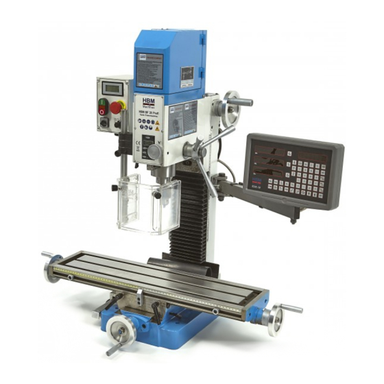
- Page 1 HBM BF 28 Profi Vario Freesmachine HBM Machines B.V. Grote Esch 1010 2841 MJ Moordrecht Tel: 0031 182 525468 Fax: 0031 182 635119 E-mail: info@hbm-machines.com Website: www.hbm-machines.com...
- Page 2 LIMITED WARRANTY We Makes every effort to assure that its products meet high quality and durability standards and warrants to the original retail consumer/purchaser of our products that each product be free from defects i n materials and workmanship as follow: This ONE YEAR LIMITED WARRANTY ON ALL PROOUCTS UNLESS SPECIFIED OTHERWISE.
- Page 3 WARNING! Keep children and visitors away. Ali visitors should be kept a safe distance from the work area Read and understand the entire instruction manual before attempting set-up or ------------------------ ,c,f this mill/ drill 14 Make the workshop chi Id proof. Use padlocks, operation .
- Page 4 MAIN TECHNICAL SPECIFICATION SPECIFICATION Drilling Capacity ..................25mm Mill Capacity ........
-
Page 5: Table Of Contents
TABLE OF CONTENTS WARRANTY ....................... WARNINGS ........................SPECIFICATIONS ..................:....TABLE OF CONTENTS ....................4 CONTENTS OF SHIPPING CONTAINER ........... -
Page 6: Warnings
WARNING Read and understand the entire contents of this Manual before attempting set•up or operation! Failure to comply may cause serious injure! CONTENTS OF SHIPPING CONTAINER Milling & Drilling Machine 3/8 Drawbar Digital Scale & Speed Readout (Optional) Test Flow Chat Operator manual Toolbox &... -
Page 7: Assembly
Assembly 1. Screw handles (A, Fig.02) onto handwheel (8, Fig.3) and tighten. Repeat for remaining handles of table. Installation ,&. WARNING! Machine is heavy! Use an appropriate lifting device and use extreme caution when moving the machine to its final, location. Fallure to comply'may cause serfous lnjuryl Fig. -
Page 8: Controls
CONTROL Longitudinal Handwheel {A, Fig. 04) Located on two side of the table. Moves table side to side. Cross Feed Handwheel {B, Fig. 04) Located on the front of the base. Moves table toward, or away from the column. Head Elevating handwheel (C, Fig.05), Fig. -
Page 9: Electrical Connections
Down feed Handles: (J, Fig. 08): Located on the right side of the head casting. Counter-clockwise movement advances the quill toward the table. Return spring retracts the handles. The knob (K, Fig. 08) must be loose before the operating the handles. The graduated dials (L, Fig. 08) on the handle base can be indexed or "zeroed"... - Page 10 Before connecting the machine to the mains, make sure that the electrical values of the mains supply are the same as those for the machine's electrical components. Use the wiring diagram (Fig. 11) for connecting the lathe to the mains supply. WARNING! Make sure the machine is properly ground! failure to do so may cause serious injury and...
- Page 11 Remover the cover of drawbar onto the motor cover (A, Fig, 14). Hold the fiat of spindle (B, Fig.15) to keep it from moving while loosening the drawbar with the 22-25 spanner i n toolbox. Loosen the drawbar approximately three to four full turns.
- Page 12 Re-adjust as required. Fig. 17 Fig.18 - 12 -...
-
Page 13: Maintenance
Maintenance Keep the maintenance of the machine tool during the operation to guarantee the accuracy and service life of the machine. 1. ln order t o retain the machine's precision and functionality, i t is essential t o treat i t with care, keep i t clean and grease and lubricate i t regularly. -
Page 14: Trouble Solution
Trouble Solution Problem Possible Cause Solution Gbs too loose on table, oolurm Readjust gibs Loci< all axes but the ooe rroving Unused feeds not locked MIi head not locked Lockrrill head T oo chatters Q.Jill too loose Tighten quill Iock T ool not oo œnter C.entertool 1 11... - Page 15 WMD25VB PARTS LIST FOR Keep Read and Understand the Operation Manual and Safety Information Bef ore Operated !
- Page 16 WMD25VB M&D ASSEMBLY BASE&COLUMN ASSEMBLY...
- Page 17 ASt& ULUMN ASStM LY PAKIS LISI PART# DESCRIPTION PART# DESCRIPTION WMD20A-0l-001 GB70-85 Cap Screw M5 X 8 Base WMD20A-0l-014 Y-Axis Gib WMD20V-02-018 Rose Connector ZAY7025FG-0l-032 Gib Screw WMD20A-0I-018 Z Axis Way Cover WMD20A-01-021 Z Axis Way Cover ZA Y7025FG-0 1-020 Y-Axis Leadscrew Lower Bracket GB1096-79...
- Page 18 Bracket B Bracket ZAY7025FG-0 1-033 Worktable GB70-85 Cap Screw MS x 14 ZAY7025FG-0 1-024 Square Nut WMD20A-0l-026 Z-Axis Scale GB70-85 Cap Screw M6X 12 WMD20A-Ol-019 Adjusta.ble Washer A ZAY7025FG-0l-023 Stop Block WMD20A-0 1-015 Z-Axis Gib ZAY7025FG-0l-034 Worktable Scale WMD20A-01-016 Swing Scale ZAY7025FG-0l-027 X-axis ZAY7025FG-0 1-050...
- Page 19 PART# DESCRIPTION PART# DESCRIPTION Cap Screw M5 X 12 WMD25VH-02-003 Spindle GB70-2000 WMD20V-01-00 l Bearing Cover JB7270.12-1994 Lock HandleM8 X 20 GBff297-94 Tapered Roll Bearing WMD20V-0 1-025 Plug 32007 WMD20V-0 1-034 Guide Pin WMD20V-0 1-002 Spindle Sleeve WMD25VH-02-00 l Headstock GBff297-94 Tapered Roll Bearing 32005...
- Page 20 WMD20V-0 l-024 Downfeed gear Shaft GB70-85 Cap ScrewM6 X 20 GB1096-79 Key4X 12 WMD25VH-02-013 Mounting Base GB78-2000 St Screw M6X 12 WMD25VH-02-012 Set Bush GB119-2000 Roll Pin BS X 10 GB893.l-86 Int Retaining Ring 10 GB894.l-86 Ext Retaining Ring WMD20V-0l-018 lndicator Pin WMD20VH-02-006 Belt Wheel...
- Page 21 ELECTRICAL BOX ELECTRICAL BOX PART LIST PART# DESCRIPTION PART# DESCRIPTION WMD20A-04-003 Ring WMD20A-04-005 Control Faceplate GB95-85 Flat Washer4 WMD20A-04-004 Electrical Box GB70-2000 Cap Screw M4X 14 WMD20A-04-006 Mounting Plate WMD20A-04-001 Supporting Losing Heat Panel GB70-2000 Cap Screw MS X 16 GB70-2000 Cap Screw M4 X 10 IB/f7590-2005...
- Page 22 ' - ----- ' - ----- Electrical Box Parts I ist (A) PART# DESCRIPTION PART# DESCRIPTION GB70-2000 Cap Washer M4 X 6 GB95-85 Flat washer 5 GB95-85 Flat Washer 4 GB70-2000 Cap Screw M5 X 20 WMD20A-04A-004 Mounting Plate WMD20A-04A-003 Control face plate WMD20A-04A-0O 1 Electrical Box...
- Page 23 · · · - - · - - - - - - - - - - - - - - - - - - - - - - - . HBM Machines B.V. Grote Esch 1010 2841 MJ Moordrecht Tel: 0031 182 525468 Fax: 0031 182 635119...
- Page 24 HBM BF 28 Profi Vario Freesmachine a. Correct label a. Connection tightened [ y ' b. Painting damage b. Correct electrical elements acn1nes c. Corrosion damage c. Earth resistance f\l/ tg,, d. Screw tightened d. Insulation resistance e. Tolerance voltage test a.
- Page 25 HBM BF 28 Profi Vario Freesmachine HBM BF 28 Profi Vario Freesmachine TOLERANCE(mm: TOLERANCE(mm; INSPECTION INSPECTION DIAGRAM DIAGRAM PERMISSIBLE ACTUAL PERMISSIBLE ACTUAL ITEM ITEM Squareness of Flatness of 0.03/300 C>.() "Z table longitudinal 0.02/150 t ' , O , ·---···--= worktable surface.
Need help?
Do you have a question about the BF 28 and is the answer not in the manual?
Questions and answers