Extron electronics TouchLink TLP 700MV User Manual
Control systems
Hide thumbs
Also See for TouchLink TLP 700MV:
- User manual (58 pages) ,
- Setup manual (4 pages) ,
- Setup manual (4 pages)

Related Manuals for Extron electronics TouchLink TLP 700MV


Summary of Contents for Extron electronics TouchLink TLP 700MV
- Page 1 User Guide TouchLink ® TLP 700MV and TLP 700TV TouchLink Touchpanel Control Systems 68-1378-01 Rev. D 01 20...
- Page 2 Safety Instructions Safety Instructions • English Istruzioni di sicurezza • Italiano AVVERTENZA: Il simbolo, , se usato sul prodotto, serve ad WARNING: This symbol, ,when used on the product, is avvertire l’utente della presenza di tensione non isolata pericolosa intended to alert the user of the presence of uninsulated dangerous all’interno del contenitore del prodotto che può...
- Page 3 より 『Extron Safety www.extron.com and Regulatory Compliance Guide』 (P/N 68-290-01) をご覧ください。 Copyright © 2008 - 2020 Extron Electronics. All rights reserved. www.extron.com All trademarks mentioned are the property of their respective owners.. Trademarks All trademarks mentioned in this guide are the properties of their respective owners.
- Page 4 Conventions Used in this Guide Notifications In this user guide, the following are used: WARNING: Potential risk of severe injury or death. Risque potentiel de blessure grave ou de mort. AVERTISSEMENT : CAUTION: Risk of minor personal injury. ATTENTION : Risque de blessure mineure. ATTENTION: Risk of property damage.
-
Page 5: Table Of Contents
Contents Introduction ............1 Configuration Software ........16 About the TLP 700MV and TLP 700TV ....1 Software Overview ..........16 Features ............. 2 Installing the Software ........17 Requirements ............. 3 Installation from the Extron Web Site ..... 17 Software ............ - Page 6 TLP 700MV and TLP 700TV • Contents...
-
Page 7: Introduction
Introduction This guide describes the function, installation and operation of the TouchLink TLP 700MV and TLP 700TV Touchpanels. Unless otherwise stated, the terms “TLP 700 series,” “TLP 700,” “touchpanel,” and “TouchLink touchpanel” refer to both models. The guide also provides information about optional accessories that are available from Extron for both panels. -
Page 8: Features
TCP/IP Network D IS Extron tr o Contact IPL 250 Closure IP Link-Ethernet Extron Motion Control Interface Detector IN1508 Extron Scaling Presentation Switcher W ER TLP 700MV M AX RS-232 7" TouchLink RS-232 Panel D IO Extron LIST I.T.E Lighting XPA 1002 Extron System... -
Page 9: Requirements
Loudspeaker — Provides audible feedback in response to events triggered by the user. Multiple mounting options — The TLP 700MV can be wall-mounted, rack-mounted, or furniture-mounted. The TLP 700TV comes with a stand that allows it to be placed on a desktop. If the stand is removed, the unit can be VESA-mounted on a wall or furniture using either of the optional Extron kits. -
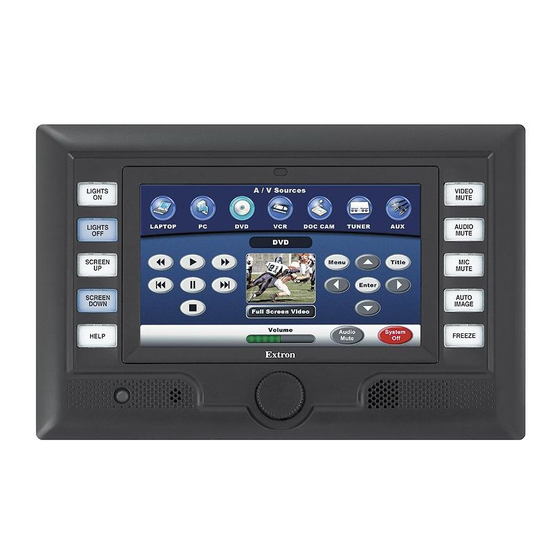
Page 10: Panel Features
Panel Features This section describes: TLP 700MV Front Panel Features and Operations TLP 700MV Rear Panel Features and Connections TLP 700TV Front Panel Features and Operations TLP 700TV Rear Panel Features and Connections TLP 700TV Base Features TLP 700MV Front Panel Features and Operations Figure 2. -
Page 11: Tlp 700Mv Rear Panel Features And Connections
There are three buttons and an LED recessed behind the bezel. These buttons are used to configure the unit and reset parameters to factory defaults: A A A B B B C C C TLP 700MV Front Panel with Bezel removed Figure 3. - Page 12 Power Connector (see figure 4 on the previous page) — Connect the two pole, 3.5 mm captive screw connector from the provided power supply to the power supply socket on the rear panel. Ensure the connections have the correct polarity as shown below: POWER Smooth...
- Page 13 ATTENTION: Always use a power supply supplied by or specified by Extron. This product is • intended for use with a UL Listed power source marked “Class 2” or “LPS” and rated 12VDC, minimum 1.0 A. Use of an unauthorized power supply voids all regulatory compliance certification and may cause damage to the supply and the end product.
-
Page 14: Tlp 700Tv Front Panel Features And Operations
Video Input (see figure 4 on page 5) — Connect an S-video or composite video source to the unit, using these two BNC connectors: For S-video, connect the Y (luminance) signal to the VID/Y input and the C (chrominance) signal to the C input. For composite video, connect the input to the VID/Y input. -
Page 15: Tlp 700Tv Rear Panel Features And Connections
Buttons (see figure 6 on the previous page) — These ten backlit push-buttons (five on either side of the screen) can be configured to execute user-defined functions using the Extron Global Configurator software (page 26). For information about creating button labels, see page 43. -
Page 16: Tlp 700Tv Base Features
The following connections are available through the back panel when the stand is in place: LED lights (see figure 7 on the previous page) —The Link LED lights green to indicate a good network connection. The Activity LED blinks yellow when network activity occurs. - Page 17 The TLP 700TV stand, which can be removed for VESA mounting, has: Three adjustable potentiometers (see figure 8 on the previous page) — These are used to control sharpness and gain for both S-video luminance (Y) and S-video chrominance (C). If a composite video signal is used, the gain is controlled by the center potentiometer (Vid/Y).
-
Page 18: On-Screen Menus
On-screen Menus This section describes: How to Access the Internal On-screen Menus • Main Screen • Volume Screen • Time Screen • Network Screen • Video Screen • Touch Calibration Screen • How to Access the Internal On-screen Menus When power is first applied to the TouchLink Panel, the unit boots up and displays the opening screen. -
Page 19: Volume Screen
The screen may need a high level of backlighting to read the screen when ambient lighting is high. With low ambient lighting, the backlighting should also be low. Auto Backlight provides a suitable amount of backlighting that is automatically calculated from the amount of ambient light detected by the light detector. -
Page 20: Time Screen
Time Screen Figure 12. Time Screen Click on the Down or Up buttons to highlight one of the adjustable time settings. Use the buttons or the volume control knob to adjust the Month, Day, Year, Hours, and Minutes. The Hours value uses the 24 hour clock. For 10 am, set Hours to 10; for NOTE: 10 pm, set Hours to 22. -
Page 21: Video Screen
Video Screen Figure 14. Video Screen The small gray rectangle provides a video preview window that allows the user to adjust the video properties. Click on the Down or Up buttons to highlight one of the adjustable video settings. Use the Down and Up buttons or the volume control knob to adjust: Contrast between 0 and 127 (default, 64) •... -
Page 22: Configuration Software
Configuration Software This section of the guide discusses the software and firmware needed to set up the Touchpanel units: Software Overview • Installing the Software • Updating the Firmware • Using the TouchLink Panel Web Pages • Using GUI Configurator •... -
Page 23: Installing The Software
Installing the Software Installation from the Extron Website Both programs can be downloaded from the Extron website (www.extron.com). Select the Download tab (figure 15, Click Software from the options at the bottom of the page ( Extron Website — Software Download Center Figure 15. -
Page 24: Updating The Firmware
Updating the Firmware Firmware for the TLP 700 can be upgraded using the Extron Firmware Loader (see below) or using your Web browser GUI (see page 19). Before starting, consult your IT team and ensure that the TLP 700 has a unique IP address. Updating Firmware Using the Extron Firmware Loader Utility NOTES: To use this method, you must have Extron Firmware Loader installed on your PC. -
Page 25: Updating Firmware From A Web Browser Gui
Updating Firmware From a Web Browser GUI NOTE: Your PC must have internet access and be on the same network as the TouchLink Panel. On the Extron Web site, select the Download tab figure 15 Click the Firmware option at the bottom of the page (see on page 17). -
Page 26: Using The Touchlink Panel Web Pages
Using the TouchLink Panel Web Pages As seen in the previous section, the TLP 700MV and TLP 700TV TouchLink Panels have default web pages that can be used to read and change the current settings of the panels. The web pages can be accessed as follows: Open your browser and enter the IP address of the TLP 700 unit into the address box. - Page 27 Click the Passwords link. This page allows the user to set Administrator and User passwords. To set a password, follow the instructions at the top of the page. NOTES: The factory configured passwords for all accounts on this device have been •...
-
Page 28: Using Gui Configurator
Using GUI Configurator This section provides an overview of the GUI Configurator program. For complete information about the program, consult the GUI Configurator help file (click on Contents in the Help menu or press the <F1> key while within the program). To use the GUI Configurator program, follow these instructions: Click the desktop icon. - Page 29 You can choose to: Start a New Project — Select the Start a New Project radio button, then click • OK. The New Project dialog box opens: Figure 24. GUI Configurator New Project Dialog Box A series of icons offer you the choice of creating a project with a template or without a template and allow you to select the size and type of Touchlink Panel.
- Page 30 Download an Existing Project from a Panel — Clicking OK opens a dialog box • that allows you to download a file that has been uploaded to a panel. Figure 26. GUI Configurator Download Project Dialog Box In the dialog box that opens, enter the IP address of the panel and use the Browse button to navigate to a folder where the file will be saved.
- Page 31 Depending on which option was selected in step 2 on page 23, GUI Configurator opens to a new or an existing project. The initial screen is divided into a series of panels offering a range of tools that are used to design or modify the project. For full details on how to use the tools, consult the help file (in the Help menu click on Contents or press the <F1>...
- Page 32 The Panel Manager dialog box opens: Figure 29. Add a TouchLink panel (b) Click on the Add Panel icon to add a new panel to the list in the left pane. Highlight the name of the panel in the left pane to display the properties of that panel in the right pane.
-
Page 33: Using Global Configurator
Using Global Configurator To configure a TouchLink Panel, you must use Global Configurator version 3.0 NOTE: or later. This section provides an overview of the Global Configurator program. For complete information about the program, consult the Global Configurator help file (click Contents in the Help menu or press the <F1>... - Page 34 Select Create A New Project and click OK. The dialog box closes, leaving the Project Settings screen. Global Configurator Project Settings Figure 31. Enter the IP Address for the TLP 700MV panel. The default value for Telnet port is 23 and HTTP port is 80. These values do not usually need to be changed.
- Page 35 Click OK and the Project Settings screen closes and is replaced by the Add Device dialog box: Global Configurator Add Device Dialog Box Figure 32. To see all the options, click on the Advanced >>> button. The button name changes to Basic <<<...
- Page 36 Click OK ( ¢ ) and the Add Device screen closes. The start-up screen, which was behind it, is now visible. The device configuration tree, in the panel to the left of the main screen, shows the IPL 250 and the available ports: Configuring an IP Link Device Figure 33.
- Page 37 The Add TouchPanel dialog box opens. Figure 35. Add Touchpanel Dialog Box. Select the correct model from the drop-down list (figure 35, Enter the IP address for the TouchLink Panel ( Set the Telnet Port, usually 23, ( ) and, if necessary, enter the password ( NOTES: The factory configured passwords for all accounts on this device have •...
- Page 38 The window now shows the GUI from the TouchLink Panel. Figure 36. GUI from TouchLink Panel added to Global Configurator. For complete instructions on how to assign functions to the buttons on the screen, see the Global Configurator help file, which is opened by clicking on Contents in the Help menu, or by pressing the <F1>...
-
Page 39: Mounting
Mounting This section outlines the various options for: Rack Mounting the TLP 700MV • Wall Mounting the TLP 700MV • Wall Mounting the TLP 700MV with a Wallbox • Desktop Mounting the TLP 700TV • Removing the TLP 700TV base for VESA Mounting •... -
Page 40: Wall Mounting The Tlp 700Mv
Wall Mounting the TLP 700MV Fire Hazard — Do not install the TLP 700MV in a fire resistant rated wall or CAUTION: partition assembly. ATTENTION : Risque d’incendie — Ne pas installer le TLP 700MV dans un mur résistant au feu ou une cloison. The TLP 700MV can be mounted in the wall or through furniture. -
Page 41: Wall Mounting The Tlp 700Mv With A Wall Box
Trim Ring Screws (4) Bezel snaps to unit (4 plcs ea side). Tighten screws to rotate locking arms. Figure 37. Secure the TLP 700MV to a Wall With Locking Arms If required, perform the initial calibration (see page 12). Replace the bezel by pressing the catches on the bezel into the corresponding holes on the front of the panel. -
Page 42: Desktop Mounting The Tlp 700Tv
Desktop Mounting the TLP 700TV The TLP 700TV comes assembled with a stand that allows it to be placed on a desktop. If required, use two screws through the two holes in the base to secure the unit to the desktop. NOTE: the three potentiometers to adjust the sharpness and gain (see... - Page 43 To use either of these kits, you must first remove the base and the plastic enclosure from the back. When the base is removed from the TLP 700TV, video connections are via BNC NOTE: connectors, and there is no audio input. To prepare the TLP 700TV for wall mounting, using either kit, follow these instructions: Remove the TLP 700TV from its packaging or, if the TLP 700TV has previously been used as a free-standing, desktop unit, remove all cables to the back of the base.
- Page 44 Remove the back cover to reveal the metal stand and the cables connecting the circuit board in the base to the touchpanel screen. Figure 41. Remove Back Cover. Cut the plastic tie holding the cables to the metal stand. Disconnect the power, LAN, audio, LED, and two BNC cables from the circuit board in the base.
- Page 45 Tilt the screen down to reveal the Phillips head screws securing the monitor to the hinged bracket at the top of the stand. Remove and save the screws for later use. Figure 43. Remove Screws. Thread the cables through the gap between the top bracket and the stand. Place the screen, face down, on a soft cloth.
- Page 46 Remove and save the three Phillips head screws holding the plastic molding to the back of the screen. Remove Molding. Figure 45. Disconnect the audio, LED, and power cables from the back panel of the screen. NOTE: Once the touchpanel base is removed, neither the LED nor the audio inputs are available.
-
Page 47: Vesa Mounting The Tlp 700Tv
Connect the video input, using the two BNC connectors (see figure , on the previous page). When the base is attached the MTP input carries both audio and video signals. These are split in the base and separate audio and video signals are sent to the touchpanel. Once the base is removed, no audio input is available and an S-video or composite video signal is input through the BNC connectors: For S-video, connect the Y (luminance) signal to the VID/Y input (white cable) and... -
Page 48: Reset Modes
Reset Modes The TLP 700MV and TLP 700TV have four reset modes that correspond to four of the five reset modes for the IP Link controllers. The modes are initiated by pressing the Reset button. To access the Reset button on the TLP 700MV, remove the bezel. See figure 3 to locate the Reset button on the TLP 700MV. -
Page 49: Button Labels
By default, the Windows installation creates a C:\Program Files\Extron\ ButtonLabelGenerator directory and places the Button Label Generator icon into a group or folder named Extron Electronics. A shortcut icon can also be placed on the PC desktop. TLP 700MV and TLP 700TV • Button Labels... -
Page 50: Using The Button-Label Generator Software
Using the Button-Label Generator Software To run the Button-Label Generator program, click on the desktop icon. Alternatively, click Start > Programs > Extron Electronics > Button Label Generator > Button Label Generator. The Button Label Generator window opens: Figure 47. -
Page 51: Replacing Button Labels
Replacing Button Labels The illustration below shows how to replace the button labels on the TLP 700MV. Although, the buttons on the TLP 700TV are slightly smaller and the labels are different dimensions, the procedure for replacing labels on either model is the same. To change the translucent button labels for either model, follow these steps, as shown in the diagram: Pull the lens from the button and add the label. - Page 52 Extron Electronics makes no further warranties either expressed or implied with respect to the product and its quality, performance, merchantability, or fitness for any particular use. In no event will Extron Electronics be liable for direct, indirect, or consequential damages resulting from any defect in this product even if Extron Electronics has been advised of such damage.
Need help?
Do you have a question about the TouchLink TLP 700MV and is the answer not in the manual?
Questions and answers