
Related Manuals for Extron electronics TouchLink TLP 710MV


Summary of Contents for Extron electronics TouchLink TLP 710MV
- Page 1 User Guide TouchLink ® TLP 710MV and TLP 710TV TouchLink Touchpanel Control Systems 68-2028-01 Rev. B 10 13...
-
Page 2: Safety Instructions
Safety Instructions Safety Instructions • English Инструкция по технике безопасности • Русский WARNING: This symbol, , when used on the product, is intended ПРЕДУПРЕЖДЕНИЕ: Данный символ, , если указан to alert the user of the presence of uninsulated dangerous voltage на... - Page 3 Extron Safety and Regulatory Compliance Guide on the Extron website. Copyright © 2013 Extron Electronics. All rights reserved. Trademarks All trademarks mentioned in this guide are the properties of their respective owners. The following registered trademarks( ®...
- Page 4 Conventions Used in this Guide In this user guide, the following are used: WARNING: A warning indicates a situation that has the potential to result in death or severe injury. CAUTION: A caution indicates a situation that may result in minor injury. ATTENTION: Attention indicates a situation that may damage or destroy the product or associated equipment.
-
Page 5: Table Of Contents
Contents Introduction ............1 Mounting ............... 35 About the TLP 710MV and TLP 710TV ....1 Rack Mounting the TLP 710MV ......35 Features ............. 1 Underwriters Laboratories Guidelines Requirements ............. 3 for Rack Mounting ........35 Computer ............3 Rack Mounting the TLP 710MV .... - Page 6 TLP 710MV and TLP 710TV • Contents...
-
Page 7: Introduction
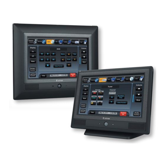
Introduction This guide describes the function, installation, and operation of the TouchLink TLP 710MV and TLP 710 TV panels. The guide also provides information about optional accessories that are available from Extron for both panels. Unless otherwise stated, the terms TLP 710 Series, TLP 710, and TouchLink touchpane refer to both models. - Page 8 Extron TLP 710MV 7" TouchLink Touchpanel Extron IPL 250 IP Link Control Processor TCP/IP Network Relay Lighting System Digital IR Control Input to Blu-ray Motion Detector I- D U TS RS-232 Extron Relay XPA 1002 U TS I- D Power Ampli er 1 Tx I 20 L OU...
-
Page 9: Requirements
Requirements Computer For a complete list of the requirements for running GUI Configurator or Global Configurator, see the Extron web page for that software. NOTE: Use Global Configurator 3.3 or a later version and GUI Configurator 1.3 or a later version to configure the TLP 710MV or TLP 710TV. Other Hardware An Extron IP Link control interface must also be connected to the same network domain as the TouchLink panel. -
Page 10: Panel Features
Panel Features This section describes: TLP 710MV Front Panel Features and Operations • TLP 710MV Rear Panel Features and Connections • TLP 710TV Front Panel Features and Operations • TLP 710TV Rear Panel Features and Connections • TLP 710MV Front Panel Features and Operations Extron TLP 710MV Front Panel Figure 2. -
Page 11: Reset Buttons And Led
Connection status LED — is unlit during normal operation. Blinks red if the connection to the IP Link controller is lost. Bezel — removable with Extron removal tool (provided). Clips fit into attachment points on the front panel (see figure 4 below) and snap into place. Figure 3. -
Page 12: Tlp 710Mv Rear Panel Features And Connections
TLP 710MV Rear Panel Features and Connections Extron Figure 5. TLP 710MV Rear Panel Features Power connector — Connect the 2-pole, 3.5 mm captive screw connector from the 12 VDC, 1.0 A power supply (not provided) to the power supply socket on the rear panel. - Page 13 ATTENTION: Always use a power supply supplied by or specified by Extron. Use of an • unauthorized power supply voids all regulatory compliance certification and may cause damage to the supply and the end product. Unless otherwise stated, the AC/DC adapters are not suitable for use in air •...
- Page 14 Extron recommends using a Power over Ethernet (PoE) power supply. Use a straight-through Ethernet cable to connect the power supply to a switch or router. This cable carries network information from the switch or router to the power supply input. A second straight-through cable carries the network information and 48 VDC from the power supply to the TLP 710MV.
-
Page 15: Tlp 710Tv Front Panel Features And Operations
TLP 710TV Front Panel Features and Operations Extron Figure 8. TLP 710TV Front Panel Features Motion sensor — is capped with a small Fresnel lens that focuses light onto the sensor. When no motion has been detected for a user-defined period of time, the unit enters sleep mode. -
Page 16: Tlp 710Tv Rear Panel Features And Connections
TLP 710TV Rear Panel Features and Connections The TLP 710TV has a stand that allows it to be placed on desktop. The stand can be removed to VESA mount the unit. Both the stand and the touchpanel have removable covers that conceal the rear panel features and protect cables that are attached to the TLP 710TV. - Page 17 Power connector — Connect the 2-pole, 3.5 mm captive screw connector from the 12 VDC, 1.0 A power supply (not provided) to the power supply socket on the rear panel. Ensure the connections have the correct polarity as shown in figure 10. NOTES: Extron recommends using the Power over Ethernet power supply.
- Page 18 MTP input — A twisted pair cable, terminated with an RJ-45 connector, provides video and audio input from an Extron RJ-45 Port MTP transmitter. The MTP port is in the top surface of the Link LED recessed area (see the arrow to the left in figure Activity LED CAUTION: Connect the MTP transmitter to the MTP socket and the network...
- Page 19 NOTE: The twisted pair cable providing the MTP (Figure ) and network (Figure ) connections should be secured together and to both the back panel and base using zip-ties as shown below. LAN Connection MTP Connection Zip-tie Cable Runway Zip-tie Figure 12.
-
Page 20: Initial Calibration
Initial Calibration This section describes: Accessing the Internal On-screen Menus • Main Screen • Volume Screen • Time Screen • Network Screen • Video Screen • Touch Calibration Screen • Accessing the Internal On-screen Menus When the TouchLink panel first has power applied, the unit boots up and displays the opening screen. -
Page 21: Volume Screen
The Sleep timer buttons determine how long the panel will be inactive before it enters Sleep mode, when the screen goes dark to save power. The time can be changed from 0 to 50,000 seconds (in 10-second increments). The time that is currently selected is shown above the buttons. -
Page 22: Time Screen
Time Screen Main Month: 06 Hours: 13 Volume Down Down Time Day: 06 Minutes: 32 Network Down Down Video Year: 2011 Down Exit Figure 15. Time Screen Use the buttons to adjust the Month, Day, Year, Hours, and Minutes. Down The Hours value uses the 24-hour clock. -
Page 23: Video Screen
Video Screen Contrast: 064 Color: 064 Main Down Down Volume Time Brightness: 128 Tint: 128 Network Down Down Video Exit Figure 17. Video Screen The small gray rectangle provides a video preview window for adjusting video properties. Use the buttons to adjust: Down Contrast between (default,... -
Page 24: Configuration Software
Configuration Software This section of the user guide provides information about: The Configuration Software • Installing the Software • Using the TouchLink Panel Web Pages • • Updating the Firmware Using GUI Configurator • Using Global Configurator • The Configuration Software Designing a graphical user interface (GUI) for the TouchLink panel takes two steps: Design the layout of the text and graphics using GUI... -
Page 25: Using The Touchlink Panel Web Pages
If required, locate the Global Configurator program on the disc or website and install that also. By default, the Installer program creates and places the Global Configurator program in the folder, where represents the version of the C:\Program Files\Extron\GCx.x Global Configurator program. During installation, there is an option to place an icon on the Windows desktop. - Page 26 Click the tab and then click in the menu in the Configuration System Settings left sidebar. This page allows the user to modify the IP settings and the date and time Network Screen Time Screen settings. These correspond to the (see page 16) and (see page 16) settings in the on-screen menus.
-
Page 27: Updating The Firmware
To upgrade the firmware, select . For more detailed instructions, Firmware Upgrade Updating Firmware from a Web Browser on page 23. Click the tab to access the Touchpanel Configuration page, which allows Touchpanel the user to alter the touchpanel and volume settings. These correspond to the Main settings (see page 14) and... - Page 28 Also from the Extron Download page, download the firmware for the TouchLink panel. Click the link on the left sidebar. Firmware Figure 23. Extron Web Page — Download Center Navigate to the TLP 710MV or TLP 710TV firmware and click Download This downloads the firmware to your computer.
-
Page 29: Updating Firmware Using Gui Configurator
Updating Firmware Using GUI Configurator Set up the computer and touchpanel as described in steps 1 and 2 in the previous section (Updating Firmware Using Extron Firmware Loader). If necessary, install the Extron Firmware Loader utility onto the computer (see Installing the Software). -
Page 30: Updating Firmware From A Web Browser
Updating Firmware from a Web Browser Power on a computer that is connected to the same network as the TLP 710. From the Extron website (www.extron.com), download the firmware for the touchpanel. Click the tab on the Extron home page Download Select the option (see figure 23). -
Page 31: Using Gui Configurator
Using GUI Configurator This section provides an overview of the GUI Configurator program. For complete information about the program, see the GUI Configurator help file (select from Contents menu or press the <F1> key while the program is running). Help NOTE: To configure the touchpanel, use GUI Configurator version 1.3 or later. - Page 32 Choose from the following options: — Clicking opens a dialog box that offers a choice of Start a New Project • project options. Figure 28. GUI Configurator New Project Dialog Box A series of icons offers the choice of creating a project with or without a template and allows the size and type of Touchlink panel to be selected.
- Page 33 — Clicking opens a Download an Existing Project from a Panel • dialog box that allows a file that has already been uploaded to a touchpanel to be downloaded for modification. Figure 30. GUI Configurator Download Project Dialog Box In the dialog box that opens, enter the IP address of the panel and use the button to navigate to a folder where the file will be saved.
- Page 34 Depending on which option was selected in step 2, GUI Configurator opens a new or existing project. The initial screen is divided into a series of panes offering a range of tools that can be used to design or modify the project. For full details on how to use these tools, see the help file (from the menu select or press the <F1>...
- Page 35 The project can be uploaded to one or more TouchLink panels. To add a panel: From the menu, select . The Panel Manager dialog box Project Add > Panel opens: Figure 32. Add a TouchLink Panel (b) In the Panel Manager dialog box, click the icon (see the Add Panel illustration to the right) to add a new panel to the left pane.
-
Page 36: Using Global Configurator
Using Global Configurator NOTE: To configure the touchpanel, use Global Configurator version 3.3 or later. This section provides an overview of the Global Configurator program. For complete information about the program, see the Global Configurator help file (select Contents from the menu or press the <F1>... - Page 37 Select and click . The dialog box closes and the Project Create A New Project Settings dialog box opens. Figure 34. Global Configurator Project Settings Enter the IP address for the IP Link controller. The default Telnet connection is port 23 and the default HTTP connection is port •...
- Page 38 Click . The Project Settings dialog box closes and is replaced by the Add Device dialog box: Figure 35. Global Configurator Add Device Dialog Box Add a device to your project as follows: To see all the options, click the button.
- Page 39 Click . The Add Device dialog box closes. The start-up screen, which was behind it, is now visible, showing the IPL 250 and the available ports: Figure 36. Configuring an IP Link Device Select . The screen shows the available options for the TouchPanel Port 1 TouchLink panel.
- Page 40 On the Add TouchPanel dialog box, do the following: Add TouchPanel Dialog Box Figure 38. Ensure the correct TouchLink panel model is selected from the drop-down menu and enter the IP address. Set the Telnet port (usually 23) and, if necessary, enter the password. Check the check box and click Import/Apply Layout...
-
Page 41: Mounting
Mounting This section outlines the various options for: Rack Mounting the TLP 710MV • Wall Mounting the TLP 710MV • Furniture Mounting the TLP 710MV • Wall Mounting the TLP 710MV with a Wallbox • Desktop Mounting the TLP 710TV • Removing the TLP 710TV base for VESA Mounting •... -
Page 42: Wall Mounting The Tlp 710Mv
Wall Mounting the TLP 710MV The following steps show how to wall-mount theTLP 710MV. Furniture-mounting is similar. Determine the best location for the TLP 710MV. Use the template provided to mark the wall and cut a hole 7.5 inches (19.05 cm) wide by 5.813 inches (14.76 cm) high. -
Page 43: Furniture Mounting The Tlp 710Mv
Furniture Mounting the TLP 710MV The TLP 710MV can be mounted into the surface of a lectern as follows: Determine the best location for the TLP 710MV. Use the template provided to mark the lectern and cut a hole 7.5 inches (19.05 cm) wide by 5.813 inches (14.76 cm) high. -
Page 44: Wall Mounting The Tlp 710Mv With A Wall Box
Wall Mounting the TLP 710MV with a Wall Box The TLP 710MV can be wall mounted using the Extron BB 710M or the Extron EWB 710M. Follow the instructions provided with the appropriate wall box. Desktop Mounting the TLP 710TV Placement without a Mounting Kit The TLP 710TV comes assembled with a stand that allows it to be placed on a desktop. -
Page 45: Mounting With A Swivel Mount Adapter
Mounting with a Swivel Mount Adapter The TLP 710TV can be mounted with the optional Extron SMA-1 swivel mount adapter. This allows the unit to be mounted permanently yet swivel up to 180° in either direction. Remove the back cover and base cover, using the provided Extron removal tool, as described in “Removing the TLP 710TV Base for VESA Mounting“... - Page 46 VESA Mounting Holes (4) Spanner Drive Security Screws (2 for each hinge) Hinges (2) Cable Runway Figure 46. Removing the Base from the Touchpanel If necessary, cut the zip tie holding the twisted pair cables to the TLP 710TV base. If necessary, remove the cables from the cable runway in the base.
-
Page 47: Vesa Mounting The Tlp 710Tv
VESA Mounting the TLP 710TV Before attaching the VESA mounting kit, remove the base and back of the TLP 710TV, as described in the previous section. If necessary, connect the cables and use a zip tie to secure them to the back of the touchpanel. -
Page 48: Reset Modes
Reset Modes The TLP 710MV and TLP 710TV have four reset modes that correspond to four of the five reset modes for the IP Link controllers. The modes are initiated by pressing the Reset button. To access the Reset button on the TLP 710MV, remove the bezel. See page 5 to locate Reset button on the TLP 710MV. - Page 49 Extron Electronics makes no further warranties either expressed or implied with respect to the product and its quality, performance, merchantability, or fitness for any particular use. In no event will Extron Electronics be liable for direct, indirect, or consequential damages resulting from any defect in this product even if Extron Electronics has been advised of such damage.
Need help?
Do you have a question about the TouchLink TLP 710MV and is the answer not in the manual?
Questions and answers