
Related Manuals for Extron electronics TLP 710CV


Summary of Contents for Extron electronics TLP 710CV
- Page 1 User Guide TouchLink ™ TLP 710CV 7" Cable Cubby TouchLink Touchpanel ® ™ 68-2117-01 Rev. A 12 11...
- Page 2 Safety Instructions • English Warning Power sources • This equipment should be operated only from the power source indicated on the product. This This symbol is intended to alert the user of important operating and equipment is intended to be used with a main power system with a grounded (neutral) conductor. The third maintenance (servicing) instructions in the literature provided with the (grounding) pin is a safety feature, do not attempt to bypass or disable it.
- Page 3 FCC Class A Notice This equipment has been tested and found to comply with the limits for a Class A digital device, pursuant to part 15 of the FCC Rules. Operation is subject to the following two conditions: This device may not cause harmful interference. This device must accept any interference received, including interference that may cause undesired operation.
- Page 4 Selectable items, such as menu names, menu options, buttons, tabs, and field names are written in the font shown here: From the File menu, select New. Click the OK button. Copyright © 2011 Extron Electronics. All rights reserved. Trademarks All trademarks mentioned in this guide are the properties of their respective owners.
-
Page 5: Table Of Contents
Installing AAPs ..........9 Updating Firmware Using Inserting the AAP Assemblies ..... 10 GUI Configurator ........26 Mounting the TLP 710CV Enclosure ....11 Updating Firmware From a Web Browser ... 27 Using GUI Configurator ......... 28 Using Global Configurator ......33 Touchpanel Features and Connectors ... - Page 6 TLP 710CV • Contents...
-
Page 7: Introduction
This guide describes the function, installation, configuration, and operation of the TLP 710CV touchpanel controllers. In this guide the terms TLP 710CV and touchpanel refer to the TLP 710CV. About the TLP 710CV The Extron TLP 710CV 7-inch Cable Cubby ®... -
Page 8: Application Diagram
TLP 710CV 7" Cable Cubby TouchLink Touchpanel Video Mounted Extron Through a Table RGB 580xi or Podium Interface Extron IPL 250 IP Link Ethernet TCP/IP Control Processor Network Figure 1. Typical Application for the TLP 710CV TLP 710CV • Introduction... -
Page 9: Requirements
An Extron IP Link control interface must also be connected to the same network domain as the TouchLink touchpanel. Suggested models include: IPL T S series (for example IPL T S4) IPL 250 IPL T CR48 IPL T SFI244 IPCP series See the Extron website (www.extron.com) for further information about these products. TLP 710CV • Introduction... -
Page 10: Installation Overview
Installation Overview This section provides an overview of the main steps required to install the TLP 710CV and You can also visit the TouchLink provides links to more detailed explanations of each step. touchpanel site at www.extron.com/touchlink for further assistance in the setup and operation of the TLP 710CV, or to enroll in online training. -
Page 11: Mounting
Installing Power Modules Preparing and Installing the AAP Assemblies Planning Before making any cuts, select the best location for the TLP 710CV. Keep in mind the following: Ensure that the edge that opens on the lid is oriented correctly. ‡... -
Page 12: Tools Required For Installation
Active or Passive AAPs are not provided and must be purchased separately (see Extron website). Single-space brackets can only be installed in one location (see the note and figure on page 9). TLP 710CV • Mounting... -
Page 13: Cutting The Table
• Ensure the table surface is at least 0.375 inches (0.95 cm) thick. There are three alternative methods of making the hole for the TLP 710CV: If using a hand router, you should purchase the TLP 710CV routing template (part number 70-980-01). -
Page 14: Running Cables
Retractor kits are available for several cable types. Up to six retractors can be installed in the TLP 710CV enclosure (three on either end). They are not provided with the TLP 710CV and must be purchased separately. -
Page 15: Preparing And Installing The Aap Assemblies
The AAP assembly organizes the AAPs onto a frame that can easily be inserted or removed from the TLP 710CV frame. Pass-through and blank AAP plates are provided with the TLP 710CV. Active or passive AAPs must be purchased separately. For the complete range of available AAPs, see the Extron website. -
Page 16: Inserting The Aap Assemblies
Attach the AAP loosely to the bracket with the supplied #4-40 captive washer nuts. NOTE: At this time, captive washer nuts should be hand tightened otherwise it is difficult to attach the brackets to the frame of the TLP 710CV (see “Inserting the AAP Assemblies”... -
Page 17: Mounting The Tlp 710Cv Enclosure
CAUTION: Do not use isopropyl alcohol or other solvents to clean the Cable Cubby. Strong solvents will ruin some finishes. Carefully lower the TLP 710CV enclosure into the hole cut in the table (see “Cutting the Table” on page 7). Ensure the trim ring is flush with the top of the table. -
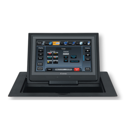
Page 18: Touchpanel Features And Connectors
Touchpanel Features and Connectors This section discusses the features and connectors of the TLP 710CV touchpanel. Front Panel With the lid down, the light sensor ( in figure 7), the screen ( ), and illumination LED ( are disabled. All three activated by opening the lid. - Page 19 Figure 7. TLP 710CV Front Panel with Bezel Removed Light Sensor — mounted on top of the screen. The sensor monitors the level of ambient light and adjusts the screen brightness. LCD screen — has a 800x480 resolution with a touch overlay. Extron software is used to design and configure a graphic user interface to display buttons, text, or icons, which have user-defined functions associated with them.
-
Page 20: Tlp 710Cv Connectors
TLP 710CV Connectors The rear panel of the TLP 710CV has a compartment that can be accessed from beneath the unit. This compartment contains the connectors for power, LAN and PoE, and MTP inputs to the touchpanel. LAN / PoE POWER 1.0A MAX... -
Page 21: Network And Power Over Ethernet Connector
Run a second straight-through cable from the PWR LAN-OUT connector of the power supply to the LAN and PoE connector on the TLP 710CV. This cable carries network information and 48 VDC. Connect the IEC power cord from the power supply to a convenient 100 VAC to 240 VAC, 50-60 Hz power source. -
Page 22: Power Connector
NOTES: • Extron recommends using the Power over Ethernet power supply. This 12 VDC, 1.0 A power supply should only be used for setup or troubleshooting. • If both power supplies are connected to the TLP 710CV, the PoE power supply takes precedence. -
Page 23: Configuration And Calibration Overview
Calibration Overview By now, the TLP 710CV must be installed in a suitable place, all necessary cables securely attached, and the unit powered on. This section provides an overview of calibrating, designing the screen layout, and adding functions to the touchscreen. -
Page 24: Initial Configuration And Calibration
The sleep timer determines how long the touchpanel will be inactive before it enters Sleep mode, when the screen goes dark to save power. The time can be changed from 0 to 833 minutes. The time that is currently selected is shown above the buttons. TLP 710CV • Initial Configuration and Calibration... -
Page 25: Volume Screen
Sounds (between 0 and 255; default 200) sets the volume of audio from any audio file playback. Line In (between 0 and 255; default 32) sets the volume of the audio signal received through the line in from an Extron MTP transmitter. TLP 710CV • Initial Configuration and Calibration... -
Page 26: Time Screen
0 and 9, “Clear,” or “.” (dot). NOTE: The factory default IP address for the TLP 710CV is 192.168.254.254 and the default subnet mask is 255.255.0.0. Consult your IT department to ensure these addresses are correctly assigned. -
Page 27: Video Screen
(see page 18). Pressing the button on any of the menu screens (not available on the touch calibration Exit screen) saves all changes and exits the calibration screens. TLP 710CV • Initial Configuration and Calibration... -
Page 28: Configuration Software
NOTE: You must use Global Configurator 3.3 or a later version and GUI Configurator 1.3 or a later version to configure the TLP 710CV. Insert the disc provided into the DVD-ROM drive of the computer. If the setup program does not start automatically, run from the DVD-ROM directory in Windows Launch.exe... -
Page 29: Using The Touchlink Touchpanel Web Pages
The web pages can be accessed as follows: Open your browser and type the IP address of the TLP 710CV unit into the address field. The browser opens the TouchLink touchpanel System Status web page, which is read-only and provides basic information about the model, date and time, and IP settings. - Page 30 Figure 19. Passwords Page To upgrade the firmware, select . More detailed instructions are found Firmware Upgrade in the “Updating Firmware from a Web Browser” section on page 27. TLP 710CV • Configuration Software...
-
Page 31: Updating The Firmware
Configurator programs (see page 22). To install from the Extron website (www.extron.com), select the tab and click Download tab. Locate the Firmware Loader and click . Follow the on-screen Software Download instructions to complete installation. TLP 710CV • Configuration Software... -
Page 32: Updating Firmware Using Gui Configurator
TCP/IP Connection Method Enter the IP address for the TLP 710CV, a Telnet port number (this will usually be 23), and a password. Click Connect In the New Firmware File “Path” pane, navigate to the file that was saved in step 4. Click button. -
Page 33: Updating Firmware From A Web Browser
This downloads the firmware to your computer. Note the folder in which the firmware file is saved. Open your browser and type the IP address of the TLP 710CV unit into the address box. TouchLink touchpanel web pages The browser opens the (see page 23). -
Page 34: Using Gui Configurator
To use the GUI Configurator program, follow these instructions: Double-click the desktop icon. The main screen opens behind the GUI Configurator Start Options dialog box. Figure 24. Opening GUI Configurator Figure 25. GUI Configurator Start Options Dialog Box TLP 710CV • Configuration Software... - Page 35 Figure 27. GUI Configurator Dialog Box to Open an Existing Project Navigate to the existing file and select it. A preview with information about the file appears in the pane on the right. TLP 710CV • Configuration Software...
- Page 36 In the dialog box that opens, enter the IP address of the touchpanel and use the button to navigate to a folder where the file will be saved. Browse Check Open the project Close Download Manager Click . The project is downloaded to your computer and opens in GUI Configurator. TLP 710CV • Configuration Software...
- Page 37 Save As dialog box appears. If the Save As dialog box appears: Browse for the location where the project file is to be saved. Enter a file name for the project. Click Save TLP 710CV • Configuration Software...
- Page 38 Automatic Close this dialog when upload completes Settings section so that the File Upload Manager screen closes automatically when the upload completes. This option can be set before or during the upload. TLP 710CV • Configuration Software...
-
Page 39: Using Global Configurator
IP Link product is similar but you should consult the Global Configurator help file for exact information about the product you are using. Double-click the GC3 desktop icon. The Global Configurator 3 Start Options box opens. Figure 32. Global Configurator 3 Start Options TLP 710CV • Configuration Software... - Page 40 If necessary, set administrator and user passwords. If required, set the date and time. Checking the box is optional. For more Set Device as GlobalViewer Host information about GlobalViewer host, see the Global Configurator help file. TLP 710CV • Configuration Software...
- Page 41 Set the Telnet port (usually 23) and the web port (usually 80). If the controller is password protected, enter the password now. In the right pane, set up a GlobalViewer tree. For information about this, see the Global Configurator help file. TLP 710CV • Configuration Software...
- Page 42 . The screen shows the available options for the TouchLink TouchPanel Port 1 touchpanel. To add the GUI Configurator project that was uploaded to the TouchLink touchpanel, click Click here to add one Figure 36. Adding a TouchLink touchpanel TLP 710CV • Configuration Software...
- Page 43 The window now shows the GUI from the TouchLink touchpanel. Figure 38. Touchpanel GUI Loaded Onto Global Configurator 3 Use Global Configurator to associate functions with the screen elements designed in GUI Configurator (see the Global Configurator help file). TLP 710CV • Configuration Software...
-
Page 44: Specifications
Video input — see S-video or composite video MTP transmitters or TLP VIM specifications Number/signal type ......1 S-video or composite video, as part of a set of proprietary signals Connector ........1 female RJ-45 Standards ........NTSC, PAL TLP 710CV • Specifications... - Page 45 Device ........33.2 BTU/hr Device and power supply ..45.9 BTU/hr Mounting Furniture mount ...... With included hardware Min./max. table thickness ....0.375" to 2.00" (0.95 cm to 5.08 cm) Enclosure type ........ Metal TLP 710CV • TLP 710CV • Specifications...
- Page 46 (22.61 +0.00/-0.05 cm W x 18.03 +0.00/-0.05 cm D) Box (under surface) ....7.40" H x 12.27" W (front/rear of unit) x 6.56" D with clamps (18.79 cm H x 31.15 cm W x 16.66 cm D with clamps TLP 710CV • TLP 710CV • Specifications...
- Page 47 MTBF ..........30,000 hours Warranty ........3 years parts and labor; touchpanel display and overlay components are covered for 1 year NOTE: All nominal levels are at ±10%. NOTE: Specifications are subject to change without notice. TLP 710CV • TLP 710CV • Specifications...
-
Page 48: Accessories And Part Numbers
IPL T S1 60-801-81 IPL T S2 60-544-81 IPL T S4 60-544-83 IPL T S6 60-544-84 IPL 250 60-1026-81 IPL T CR48 60-544-85 IPL T SFI244 60-544-86 IPCP 305 60-1072-02 IPCP 505 60-1071-02 TLP 710CV • Accessories and Part Numbers... -
Page 49: Reset Modes
Reset Modes The TLP 710CV has four reset modes that correspond to four of the five reset modes for the IP Link controllers. The modes are initiated by pressing the Reset button. To access the Reset button on the TLP 710CV, remove the faceplate. - Page 50 Extron Warranty Extron Electronics warrants this product against defects in materials and workmanship for a period of three years from the date of purchase; touchscreen display and overlay components are covered for 1 year. In the event of malfunction during the warranty period attributable directly to faulty workmanship and/or materials, Extron Electronics will, at...
Need help?
Do you have a question about the TLP 710CV and is the answer not in the manual?
Questions and answers