Extron electronics TLP 700MV User Manual
Touchlink touchpanel control systems
Hide thumbs
Also See for TLP 700MV:
- Setup manual (4 pages) ,
- User manual (52 pages) ,
- Setup manual (4 pages)
Table of Contents
Advertisement
Quick Links
Download this manual
See also:
Setup Manual
Advertisement
Table of Contents

Related Manuals for Extron electronics TLP 700MV


Summary of Contents for Extron electronics TLP 700MV
- Page 1 User Guide TouchLink™ TLP 700MV and TLP 700TV TouchLink Touchpanel Control Systems 68-1378-01 Rev. B 10 10...
- Page 2 Precautions Safety Instructions • English Warning Power sources • This equipment should be operated only from the power source indicated on the product. This This symbol is intended to alert the user of important operating and maintenance equipment is intended to be used with a main power system with a grounded (neutral) conductor. The (servicing) instructions in the literature provided with the equipment.
- Page 3 FCC Class A Notice This equipment has been tested and found to comply with the limits for a Class A digital device, pursuant to part 15 of the FCC Rules. Operation is subject to the following two conditions: This device may not cause harmful interference. This device must accept any interference received, including interference that may cause undesired operation.
-
Page 5: Table Of Contents
Contents Introduction ..........Accessories and Part Numbers ....About the TLP 700MV and TLP 700TV ..... 1 Included Parts ..........37 Features ............2 Optional Parts ..........37 Requirements ........... 3 Software ............3 Mounting ..........Hardware ............. 3 Rack Mounting the TLP 700MV...... 38 Underwriters Laboratories Guidelines for Panel Features ......... - Page 6 TLP 700MV and TLP 700TV • Contents...
-
Page 7: Introduction
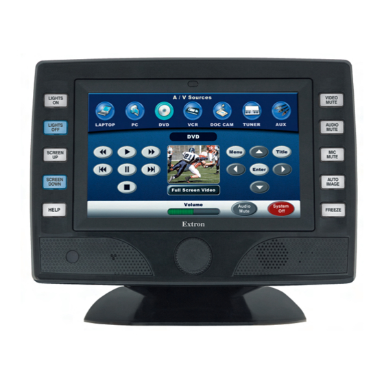
Unless otherwise stated, the terms “TLP 700 series” and “TLP 700” refer to both models. About the TLP 700MV and TLP 700TV The Extron TLP 700MV is a wall mounted TouchLink panel. The screen displays graphic objects and text, which are associated with user-defined functions. The touch overlay allows the user to initiate or activate functions by touching the objects on the screen. -
Page 8: Features
When a user approaches the screen, the panel detects motion and is reactivated. Loudspeaker — provides audible feedback in response to events triggered by the user. TLP 700MV and TLP 700TV • Introduction... -
Page 9: Requirements
37 for the part numbers. Color Options for TLP 700MV — The TLP 700MV is available in different color versions. Customization kits — A range of kits are available to customize the TouchLink panel. See optional parts the list of on page 37 for the part numbers. -
Page 10: Panel Features
(page 21). These can be configured for a range of user-defined functions, using the Extron Global Configurator software (page 26). Speaker — A single 2 watt speaker provides audible feedback for the user. TLP 700MV and TLP 700TV • Panel Features... - Page 11 11). Reset LED — is visible only when the bezel has been removed. It lights as an indicator for the Reset modes. For further information see “Reset Modes” on page 46. TLP 700MV and TLP 700TV • Panel Features...
-
Page 12: Tlp 700Mv Rear Panel Features And Connections
National Electrical Code ANSI/NFPA 70, article 75 and the Canadian Electrical Code part 1, section 16. The power supply shall not be permanently fixed to building structure or similar structure. TLP 700MV and TLP 700TV • Panel Features... - Page 13 C (chrominance) signal to the C input. For composite video, connect the input to the VID/Y input. Network Connector — The TLP 700MV connects to an Ethernet LAN using a twisted pair cable, terminated with an RJ-45 connector (see the figure at right).
-
Page 14: Tlp 700Tv Front Panel Features And Operations
(see page 11). Reset LED — recessed behind the bezel. It lights as an indicator for the Reset modes. For further information see “Reset Modes” on page 46. TLP 700MV and TLP 700TV • Panel Features... -
Page 15: Tlp 700Tv Rear Panel Features And Connections
Audio input is available only from an Extron MTP transmitter through the RJ-45 connector in the base of the unit. If the base is removed from the TLP 700TV, connections are via BNC connectors and there is no audio input. TLP 700MV and TLP 700TV • Panel Features... -
Page 16: Tlp 700Tv Base Features
RJ-45 connectors. Security mounting — If required, secure the unit to the desktop, using two screws, as described on page 41. TLP 700MV and TLP 700TV • Panel Features... -
Page 17: Initial Calibration
With low ambient lighting, the backlighting should be low. Auto Backlight provides a suitable amount of backlighting that is automatically calculated from the amount of ambient light detected by the light detector. TLP 700MV and TLP 700TV • Initial Calibration... -
Page 18: Volume Screen
Sounds (between 0 and 255) sets the volume of audio from any audio file playback. Line In (between 0 and 255) sets the volume of the audio signal received through the line in from and Extron MTP transmitter. TLP 700MV and TLP 700TV • Initial Calibration... -
Page 19: Time Screen
NOTE: The factory default IP address for the TLP 700MV is 192.168.254.254. The default subnet mask is 255.255.0.0. Consult with your IT Department to ensure these addresses are correctly assigned. -
Page 20: Video Screen
Repeat until all four boxes have been pressed and calibrated. At that point the screen returns to the Main screen (see page 11). To exit from the on-screen menus, press the Exit button in the bottom left corner of the menu screens. TLP 700MV and TLP 700TV • Initial Calibration... -
Page 21: Control Software
After assigning the control functions, the project is rebuilt and uploaded to the IP Link control interface. These two programs provide versatility and adaptability for configuration and control of an A/V system as it grows and evolves. TLP 700MV and TLP 700TV • Control Software... -
Page 22: Installing The Software
Navigate to GUI Configurator or Global Configurator and click Download next to the program. Follow the on-screen instructions to complete installation. A folder is created on the C drive and an icon may be placed on the desktop. TLP 700MV and TLP 700TV • Control Software... -
Page 23: Updating The Firmware
Make a note of the folder in which the firmware file is saved. Open the Extron Firmware Loader. The Add Device... window opens. Select TLP 700MV or TLP 700TV from the device list. Select TCP/IP from the connection method. Enter the IP address for the TLP 700, a Telnet port number, and, if necessary, the administrator password. -
Page 24: Updating Firmware From A Web Browser
Please Wait...”. The TouchLink Panel restarts after the firmware is loaded. on-screen menus When the firmware is installed, calibrate the panel, using the (see page 11) or the TouchLink panel web pages (see page 19). TLP 700MV and TLP 700TV • Control Software... -
Page 25: Using The Touchlink Panel Web Pages
As seen in the previous section, the TLP 700MV and TLP 700TV TouchLink Panels have default web pages that can be used to read and change the current settings of the panels. The web pages can be accessed as follows: Open your browser and type the IP address of the TLP 700 unit into the address box. - Page 26 Click on the Touchpanel tab, which allows the user to alter the TouchLink panel and volume settings. These correspond to the Main settings (see page 11) and Volume settings (see page 12) in the on-screen menus. Figure 15. TLP 700 Touchpanel Tab: Configuration Page TLP 700MV and TLP 700TV • Control Software...
-
Page 27: Using Gui Configurator
Click on the desktop icon. The program opens at the main screen with the GUI Configurator Start Options dialog box in front. Figure 16. GUI Configurator: Main and GUI Configurator Start Options Screens Figure 17. GUI Configurator Start Options Dialog Box TLP 700MV and TLP 700TV • Control Software... - Page 28 If you are working on the project, leave the Open as read-only box unchecked. Click Open to open the file. The project opens in GUI Configurator. TLP 700MV and TLP 700TV • Control Software...
- Page 29 Browse button to navigate to a folder where the file will be saved. Check Open the project and Close Download Manager. Click on OK. The project is downloaded to your computer and opens in GUI Configurator. TLP 700MV and TLP 700TV • Control Software...
- Page 30 The project can be uploaded to one or more TouchLink Panels. To add a panel, to which the project can be uploaded: From the Project menu, select Add > Panel: Figure 22. Add a TouchLink panel (a) TLP 700MV and TLP 700TV • Control Software...
- Page 31 You can also choose to upload to certain TouchPanels from the list of TouchLink Panels found within the Devices section of the File Upload Manager screen during the upload process. TLP 700MV and TLP 700TV • Control Software...
-
Page 32: Using Global Configurator
Global configurator help file for exact information about the product you are using. Click on the GC3 desktop icon. The Global Configurator 3 Start Options box opens. Figure 24. Global Configurator 3 Start Options TLP 700MV and TLP 700TV • Control Software... - Page 33 Project Settings screen. Figure 25. Global Configurator Project Settings Enter the IP Address for the TLP 700MV panel. The default Telnet connection is port 23 and HTTP is port 80, so these values do not usually need to be changed.
- Page 34 Set the telnet port (usually 23) and the web port (usually 80). If the controller is password protected, enter the password now. In the right pane, set up a GlobalViewer tree. For information about this, refer to the Global Configurator help file. TLP 700MV and TLP 700TV • Control Software...
- Page 35 Select Touchpanel Port 1. The screen shows the available options for the TouchLink Panel. To add the GUI Configurator project that was uploaded to the TouchLink Panel, click Click here to add one. Figure 28. Adding a TouchLink panel TLP 700MV and TLP 700TV • Control Software...
- Page 36 For complete instructions on how to assign functions to the buttons on the screen, see the Global Configurator help file, which is opened by clicking on Contents in the Help menu, or by pressing the <F1> key while within the program. TLP 700MV and TLP 700TV • Control Software...
-
Page 37: Specifications
Number/signal type ......1 S-video or composite video Connectors ........2 female BNC Nominal levels ........ 1 Vp-p for Y of S-video and for composite video 0.3 Vp-p for C of S-video Impedance ........75 ohms Standards ........NTSC, PAL TLP 700MV and TLP 700TV • Specifications... -
Page 38: Audio Output
Vibration ........ISTA 1A in carton (International Safe Transit Association) Regulatory compliance Safety ........CE, c-UL, UL EMI/EMC ......... CE, C-tick,FCC Class A, ICES, VCCI Environmental ......Complies with the applicable requirements of RoHS and WEEE. MTBF ..........30,000 hours TLP 700MV and TLP 700TV • Specifications... - Page 39 Warranty ........3 years parts and labor; touchscreen display and overlay components are covered for 1 year NOTES: All nominal levels are at ±10%. Specifications are subject to change without notice. TLP 700MV and TLP 700TV • Specifications...
- Page 40 Video input — see S-video or composite video MTP transmitters' specifications Number/signal type ......1 S-video or composite video Connectors ........With base attached: 1 female RJ-45 connector Without base: 2 male BNC connectors on pigtails Standards ........NTSC, PAL TLP 700MV and TLP 700TV • Specifications...
- Page 41 Enclosure dimensions ..... 7.7" H x 9.4" W x 8.2" D (19.6 cm H x 23.9 cm W x 20.7 cm D) (Includes base. Total height and depth depends on screen tilt. See the following diagrams.) TLP 700MV and TLP 700TV • Specifications...
- Page 42 MTBF ..........30,000 hours Warranty ........3 years parts and labor; touchscreen display and overlay components are covered for 1 year NOTES: All nominal levels are at ±10%. Specifications are subject to change without notice. TLP 700MV and TLP 700TV • Specifications...
-
Page 43: Accessories And Part Numbers
TR 700M trim ring (for TLP 700MV) TLP 700MV button labels 33-1792-01 TLP 700TV button labels 33-1793-01 Extron Software Products DVD TLP 700MV • Setup Guide or TLP 700TV • Setup Guide Optional Parts Description Part Number RM 700M rack mounting kit for TLP 700MV 70-683-01... -
Page 44: Mounting
(such as the use of power strips). Rack Mounting the TLP 700MV The TLP 700MV can be mounted in any standard 19-inch equipment rack, using the optional Extron RM 700M rack mounting kit (part number 70-683-01). Follow the instructions provided with the kit. -
Page 45: Wall Mounting The Tlp 700Mv
Extron TR 700M trim ring to conceal any ragged edges when the hole is cut in the wall or furniture. To mount the TLP 700MV directly into a wall, follow these steps. The steps are similar if the unit is mounted in furniture (such as a podium or table). -
Page 46: Wall Mounting The Tlp 700Mv With A Wall Box
Wall Mounting the TLP 700MV with a Wall Box The TLP 700MV can be wall mounted using either the Extron BB 700M (part number 70-690-01) or the Extron EWB 700 (part number 60-1100-0x). In either case follow the instructions provided with the wall box. -
Page 47: Desktop Mounting The Tlp 700Tv
CAUTION: The left RJ-45 connector on the back of the TLP 700MV (with the yellow and green LEDs) must be connect to a network. The right RJ-45 connector must be connected to an Extron MTP Transmitter. The MTP transmitter uses higher voltages than a LAN and inputting those voltages on the network connection damages the TLP 700MV. - Page 48 Squeeze the sides of the front plate at the top so that the tabs are no longer seated in the slots. Figure 40. Squeeze Sides of the Back Cover. TLP 700MV and TLP 700TV • Mounting...
- Page 49 Tilt the screen down to reveal the Phillips head screws securing the monitor to the hinged bracket at the top of the stand. Remove and save the screws for later use. Figure 43. Remove Screws. TLP 700MV and TLP 700TV • Mounting...
- Page 50 Figure 44. Thread Cables into Place. Remove and save the three Phillips head screws holding the plastic molding to the back of the screen. Figure 45. Remove Molding. TLP 700MV and TLP 700TV • Mounting...
-
Page 51: Vesa Mounting The Tlp 700Tv
To VESA mount the TLP 700TV with the LPVM-1, follow the instructions provided with the mounting kit. To mount the TLP 700TV with the VM 700T and a third-party VESA mounting kit, follow the instructions provided with the VM 700T and the third-party kit. TLP 700MV and TLP 700TV • Mounting... -
Page 52: Reset Modes
IP Link controllers. The modes are initiated by pressing the Reset button. To access the Reset button on the TLP 700MV, remove the bezel. See page 5 to locate the Reset button on the TLP 700MV. -
Page 53: Button Labels
Replacing Button Labels Button Label Software Installing or Replacing Button Labels Printed labels are included with the TLP 700MV and TLP 700TV. In addition, users can write on blank labels, purchase additional sheets of printed button labels from Extron (see... - Page 54 Figure 47.Button Label Generator Software In the Systems selection box, choose the TLP 700MV or the TLP 700TV option to match the button label size and quantities for your TouchLink Panel. Using standard Windows controls, you can create and print labels that can be placed in the clear button caps on the front panel of the switcher.
-
Page 55: Replacing Button Labels
Replacing Button Labels The illustration below shows how to replace the button labels on the TLP 700MV. Although, the buttons on the TLP 700TV are slightly smaller and the labels are different dimensions, the procedure for replacing labels on either model is the same. To change the... - Page 56 TLP 700MV and TLP 700TV • Button Labels...
- Page 57 Extron Warranty ® Extron Electronics warrants this product against defects in materials and workmanship for a period of three years from the date of purchase; touchscreen display and overlay components are covered for 1 year. In the event of malfunction during the warranty period attributable directly to faulty workmanship and/or materials, Extron Electronics will, at its option, repair or replace said products or components, to whatever extent it shall deem necessary to restore said product to proper operating condition, provided that it is returned within the warranty period, with proof of purchase and description of malfunction to:...
- Page 58 Installation Checklist Installation of the TLP 700MV and TLP 700TV can be divided into five main sections: Step 1 — Mount the TouchLink panel (select one option): … Rack mount the TLP 700MV (page 38). … Wall mount the TLP 700MV...
Need help?
Do you have a question about the TLP 700MV and is the answer not in the manual?
Questions and answers