Table of Contents
Advertisement
Quick Links
Download this manual
See also:
User Manual
Advertisement
Table of Contents

Related Manuals for Extron electronics TLP 350CV


Summary of Contents for Extron electronics TLP 350CV
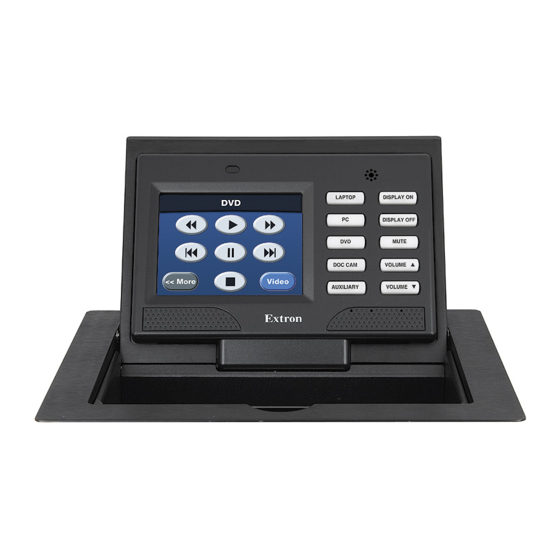
- Page 1 Installation Guide Architectural Connectivity TLP 350CV TouchLink 3.5” Cable Cubby Touchpanel ™ ® 68-1692-01 Rev. B 08 10...
- Page 2 Precautions Safety Instructions • English Warning Power sources • This equipment should be operated only from the power source indicated on the product. This This symbol is intended to alert the user of important operating and mainte- equipment is intended to be used with a main power system with a grounded (neutral) conductor. The third nance (servicing) instructions in the literature provided with the equipment.
- Page 3 WARNING: A warning warns of things or actions that might cause injury, death, or other severe consequences. Copyright © 2011 Extron Electronics. All rights reserved. Trademarks All trademarks mentioned in this guide are the properties of their respective owners.
-
Page 5: Table Of Contents
Initial Configuration ......About This Guide ..........1 Front Panel Controls and Indicators ....12 About the TLP 350CV ........1 Configuring the TLP 350CV (Initial Setup) ..13 Features ............2 Internal On-Screen Menus ......13 Requirements ........... 4 IP (Network) .......... - Page 6 TLP 350CV • Contents...
-
Page 7: Introduction
Using the video input, the panel can monitor video source devices whether as a preview aid or a personal viewer for the operator. In this guide the terms TLP 350CV, panel and touch panel refer to the TLP 350CV. TLP 350CV • Introduction... -
Page 8: Features
Features TLP 350CV features include: 3.5 inch LCD screen — displays a wide range of customizable graphics. Touch screen overlay — provides simple and intuitive control over a range of functions by touching on-screen icons. Built-in speaker — provides audible feedback when a button is pressed. - Page 9 3.5" TouchLink™ Panel Cable Cubby Video V-SY WIDT P SYN Mounted Extron B 580 through a table IR/S RGB 580xi or podium Interface Extron IPL 250 IP Link Ethernet TCP/IP Control Processor Network Figure 1. TLP 350CV Application TLP 350CV • Introduction...
-
Page 10: Requirements
Visit the touchlink panel site at www.extron.com/touchlink for further assistance in the setup and operation of the TLP 350CV and TLP 350CV, or to enroll in online training. For additional assistance with the touchlink panels, call 1.800.633.9877. TLP 350CV • Introduction... -
Page 11: Preparing The Table
Mount and connect the power supply to the TLP 350CV, Connect a LAN, If using the video monitoring capabilities, make all video input connections, Apply power and follow the on-screen instructions to set up the TLP 350CV for first time operation. TLP 350CV • Prepare the Table... -
Page 12: Cutout Dimensions
Cable Cubby models. Double-check before you cut: If using a routing template, be certain it is the correct template for the TLP 350CV. If using a CNC router, be certain the correct dimensions for the TLP 350CV are entered. -
Page 13: Mounting The Enclosure
Mounting the Enclosure Installing the Power Module, Cables and AAPs each TLP 350CV includes pass-through AAPs and a power module. A wide range of passive AAPs are also available allowing direct connection of cables from the top and underneath the AAPs. See www.extron.com... -
Page 14: Install The Power Module And Shelf Assemblies
The included power module takes up two (US) or three (Int’l) AAP spaces and must be installed on the left side of the TLP 350CV enclosure. Install the power module and AAP assembly into position at the desired location and elevation. -
Page 15: Mounting The Enclosure
CAUTION: Do not overtighten the screw clamps. Overtightening can bend the horizontal flange of the clamp. Tighten the wingnuts to lock the clamps in position. 5. Tighten Wingnut 4. Tighten Screw Front View TLP 350CV • Mounting the TLP 350CV... -
Page 16: Connecting The Touch Panel
Mounting the Power Supply (US models only) Connecting the TLP 350CV The rear panel of the TLP 350CV located on the bottom of the enclosure, provides all required connections. The panel requires an IP Link controller for operation, but may be configured without one connected. -
Page 17: Mounting The Power Supply (Us Models Only)
CAUTION: Always use a power supply supplied or specified by extron for use with the TLP 350CV. Use of an unauthorized power supply voids all regulatory compliance certification and may cause damage to the supply and the TLP 350CV. Unless otherwise stated, the AC/DC adapters are not suitable for use in air handling spaces or in wall cavities. -
Page 18: Initial Configuration
Initial Configuration This section provides information on the front panel controls and indicators, the on-screen menus used to configure the TLP 350CV, and calibration of the touchscreen. Front Panel Controls and Indicators Configuring the TLP 350CV (Initial Setup) Internal On-screen Menus... -
Page 19: Configuring The Tlp 350Cv (Initial Setup)
Speaker — Provides audio feedback of button or panel presses. Configurable Side buttons — 10 dedicated, customizable function buttons provide quick access to key functions. A set of 6 buttons with alternative labels is included with the TLP 350CV. There are also additional titles available. Button Replacement on page 40, for available labels, ordering instructions, and a procedure for changing the buttons. -
Page 20: Main Menu
Auto Backlight button to toggle Auto backlight off and on. Maximum brightness cannot exceed the backlight setting (see above). LED Backlight An LeD backlight illuminates the ten buttons next to the screen. Use the on-screen button to toggle the option Off and On. TLP 350CV • Initial Configuration... - Page 21 Greenwich Mean Time (GMT) offset, and Year: 2010 DST. Values are also resynchronized each day at midnight or by pressing the recessed front panel menu button for Main 10 seconds. Pressing main returns you to the main setup screen. TLP 350CV • Initial Configuration...
-
Page 22: Ip (Network)
If a mistake is made, press CLR, then repeat step 2 255.255.000.000 until all the octets have been set correctly. DHCP DHCP Main Toggles DHCP Off and On. Generally the TLP 350CV should be assigned a static IP to avoid communications errors on local networks. TLP 350CV • Initial Configuration... -
Page 23: Video
Once all four boxes have been calibrated the screen “Internal automatically returns to the Main menu (see On-screen Menus” on page 13). The touch screen is now calibrated and ready for configuration or normal operation. TLP 350CV • Initial Configuration... -
Page 24: Configuration Software
These two programs provide versatility and adaptability for configuration and control of an A/V system as it grows and evolves. both are included on the disc provided with the TLP 350CV and are also available free on the extron website at www.extron.com. each contains an extensive help file to guide project development. -
Page 25: Gui Configurator
Using the TouchLink Panel Web Pages The TLP 350CV TouchLink panel has default web pages that can be used to read and change the current settings of the panels. The web pages can be accessed as follows: Open your browser and type the IP address of the TLP 350 unit into the address box. - Page 26 Click on the Touchpanel tab, which allows the user to alter the Touchpanel and volume settings. These correspond to the Main settings (see page 8) and Volume settings (see page 9) in the on-screen menus. TLP 350CV • Configuration Software...
- Page 27 Figure 10. Touchpanel Configuration TLP 350CV • Configuration Software...
-
Page 28: Using Gui Configurator
Help Menu or press the F1 key while within the program). NOTE: To configure the TLP 350CV, use GUI Configurator version 1.1 or later. To use the GUI Configurator program, follow these instructions: Click on the desktop icon. A splash screen appears momentarily and then the program opens at the main screen behind the “GUI Configurator Start Options”... - Page 29 A series of icons offer the choice of creating a project with or without a template and allows you to select the size and type of Touchlink panel. If you are creating a project from an existing template, you can use the factory-loaded templates or select a previously created template. TLP 350CV • Configuration Software...
- Page 30 Check “Open the project” and, “Close Download Manager”. Click on OK. The project will be downloaded to your computer and will open in GUI Configurator. TLP 350CV • Configuration Software...
- Page 31 The project can be uploaded to one or more TouchLink panels. To add a panel, to which the project can be uploaded: From the Project menu, select Add > Panel: Figure 17. Add a TouchLink panel (5a) TLP 350CV • Configuration Software...
- Page 32 TouchPanels from the list of TouchLink panels found within the Devices section of the File Upload Manager screen during the upload process. TLP 350CV • Configuration Software...
-
Page 33: Using Global Configurator
Using Global Configurator NOTE: To configure the TLP 350CV, use Global Configurator version 3.0.4 or later. This section provides an overview of the Global Configurator program. For complete information about the program, consult the Global Configurator help file (click on Contents in the Help menu or press the F1 key while within the program). - Page 34 Figure 20. Global Configurator Project Settings enter the IP Address for the TLP 350CV panel. The default Telnet connection is port 23 and HTTP is port 80, so these values do not usually need to be changed. If necessary, set Administrator and User passwords.
- Page 35 Set the telnet port (usually 23) and the web port (usually 80). If the controller is password protected, enter the password now. In the right pane, set up a GlobalViewer tree. For information about this, refer to the Global Configurator help file. TLP 350CV • Configuration Software...
- Page 36 Select Touchpanel Port 1. The screen shows the available options for the TouchLink panel. To add the GUI Configurator project that was uploaded to the TouchLink panel, click “Click here to add one.” Figure 23. Adding a TouchLink panel TLP 350CV • Configuration Software...
- Page 37 Touchpanel GUI Loaded Onto Global Configurator 3 you must now use Global Configurator to associate functions with the screen elements that you designed in GUI Configurator. The steps for carrying this out can be found in the Global Configurator help file. TLP 350CV • Configuration Software...
-
Page 38: Reference Information
Default gateway = 0.0.0.0 DHCP = off Program control ......extron Global Configurator 3.0 or higher GUI Configurator for windows ® extron Simple Instruction Set (SIS ™ ™ Microsoft ® Internet explorer ® ver. 6 or higher, Telnet TLP 350CV • Reference Information... - Page 39 Operating: +32 to +122 °F (0 to +50 °C) / 10% to 90%, noncondensing Cooling .......... Convection, no vents Mounting Furniture mount ...... with included hardware Min./max. table thickness ....0.375" to 2.00" (0.95 cm to 5.08 cm) enclosure type ........ Metal Dimension diagram examples TLP 350CV • Reference Information...
- Page 40 (18.85 cm H x 27.6 cm w x 14.32 cm D with clamps) Product weight ....... 5.8 lbs (2.6 kg) Shipping weight ......9 lbs (4 kg) Vibration ........ISTA 1A in carton (International Safe Transit Association) TLP 350CV • Reference Information...
- Page 41 MTbF ..........30,000 hours warranty ........3 years parts and labor; touchscreen display and overlay components are covered for 1 year NOTES: All nominal levels are at ±10%. Specifications are subject to change without notice. TLP 350CV • Reference Information...
-
Page 42: Part Numbers (Included Parts)
60-1017-021D TLP 350CV (Universal - black anodized) 60-1017-020J TLP 350CV (Universal - brushed aluminum) 60-1017-021J TLP 350CV (black anodized - no AC outlet) 60-1017-0200 TLP 350CV(brushed aluminum - no AC outlet) 60-1017-0210 Default button kit (10), preinstalled Power Supply, 12 VDC, 1.0 A... -
Page 43: Accessories (Optional)
IPL T S2 60-544-81 IPL T S4 60-544-83 IPL T S6 60-544-84 IPL 250 60-1026-81 IPL 500 60-1071-01 IPL T CR 48 60-544-05 IPL T SFI 244 60-544-06 System 208 60-1051-02 Single-space AAP bracket Kit 70-693-01 TLP 350CV • Reference Information... -
Page 44: Reset Modes, Button Replacement, Firmware Updates
Button Replacement Updating Firmware Reset Modes The TLP 350CV has four reset modes that correspond to four of the five reset modes for the IP Link controllers. The modes are initiated by pressing the reset button. Using a paper clip, push through the reset access hole on the right side of the faceplate as shown below. - Page 45 (< 1 sec.). panel configurations. NOTE: Nothing happens if the momentary Resets all IP options. press does not occur within 1 second. Removes scheduling settings. Removes/clears all files from the TLP 350CV. TLP 350CV • Reset Modes and Button Replacement...
-
Page 46: Button Kits
The downloadable order form shows all the buttons available for the TLP 350CV. Button Replacement To replace one or more buttons on the front panel of the TLP 350CV: Remove power from the TLP 350CV. The faceplate is snapped on and held in four places, two on top and two at the bottom of the faceplate. -
Page 47: Updating Firmware
Updating Firmware Firmware for the TLP 350CV can be upgraded using the extron Firmware Loader, a web browser and the default web pages, or GUI Configurator. before starting, consult your IT team and ensure that the TLP 350CV has a unique IP address. - Page 48 “Connection Method” dropdown. Figure 29. Add Device Dialog enter the IP address for the TLP 350CV, a Telnet port number (23), and, if necessary, a password. Click Add. The firmware loader opens. NOTE: Administrator level privileges are required to upload firmware to extron devices.
-
Page 49: Updating Firmware Using Gui Configurator
“Transfer Complete!” message appears, click File | Exit to close the Firmware Loader. Updating Firmware Using GUI Configurator Power on a computer with internet access and ensure the computer and the TLP 350CV are connected to the same network. If necessary, install the Extron Firmware Loader utility onto the computer (see step 3 of the previous section). -
Page 50: Updating Firmware From A Web Browser
41.) Make a note of the folder where the firmware file is saved. Open a browser and type the IP address of the TLP 350CV into the address box. The Using the TouchLink Panel Web browser opens the TouchLink panel web pages (see Pages on page 19). - Page 51 Extron Electronics makes no further warranties either expressed or implied with respect to the product and its quality, performance, merchantability, or fitness for any particular use. In no event will Extron Electronics be liable for direct, indirect, or consequential damages resulting from any defect in this product even if Extron Electronics has been advised of such damage.
Need help?
Do you have a question about the TLP 350CV and is the answer not in the manual?
Questions and answers