Table of Contents
Advertisement
Quick Links
See also:
Setup Manual
Advertisement
Table of Contents

Related Manuals for Extron electronics TouchLink TLP 710MV


Summary of Contents for Extron electronics TouchLink TLP 710MV
- Page 1 User Guide TouchLink ™ TLP 710MV and TLP 710TV TouchLink Touchpanel Control Systems 68-2028-01 Rev. A 09 11...
- Page 2 Safety Instructions • English Warning Power sources • This equipment should be operated only from the power source indicated on the product. This This symbol is intended to alert the user of important operating and equipment is intended to be used with a main power system with a grounded (neutral) conductor. The third maintenance (servicing) instructions in the literature provided with the (grounding) pin is a safety feature, do not attempt to bypass or disable it.
- Page 3 FCC Class A Notice This equipment has been tested and found to comply with the limits for a Class A digital device, pursuant to part 15 of the FCC Rules. Operation is subject to the following two conditions: This device may not cause harmful interference. This device must accept any interference received, including interference that may cause undesired operation.
- Page 4 Selectable items, such as menu names, menu options, buttons, tabs, and field names are written in the font shown here: From the File menu, select New. Click the OK button. Copyright © 2011 Extron Electronics. All rights reserved. Trademarks All trademarks mentioned in this guide are the properties of their respective owners...
-
Page 5: Table Of Contents
Contents Specifications Introduction ............34 ............1 About the TLP 710MV and TLP 710TV ....1 Features .............. 1 Accessories and Part Numbers ......40 Requirements ............3 Included Parts ........... 40 Computer Software and Hardware ....3 Optional Parts ........... 40 Other Hardware .......... - Page 6 TLP 710MV and TLP 710TV • Contents...
-
Page 7: Introduction
Introduction This guide describes the function, installation, and operation of the TouchLink ™ TLP 710MV and TLP 710TV panels. The guide also provides information about optional accessories that are available from Extron for both panels. Unless otherwise stated, the terms “TLP 710 series,” “TLP 710,” “touchpanel,” and “TouchLink panel”... - Page 8 Extron TLP 710MV 7" TouchLink Touchpanel Extron IPL 250 IP Link Control Processor TCP/IP Network Relay Lighting System Digital IR Control Input to Blu-ray Motion Detector I- D U TS RS-232 Extron Relay XPA 1002 U TS I- D Power Ampli er 1 Tx I 20 L OU...
-
Page 9: Requirements
Requirements Computer Software and Hardware The following system requirements are recommended for running GUI Configurator 1.3 or Global Configurator 3.3: • Operating System – Microsoft ® Windows ® XP SP2, Windows Vista ® , or Windows 7 • CPU – Intel 1.2 GHz or compatible processor ®... -
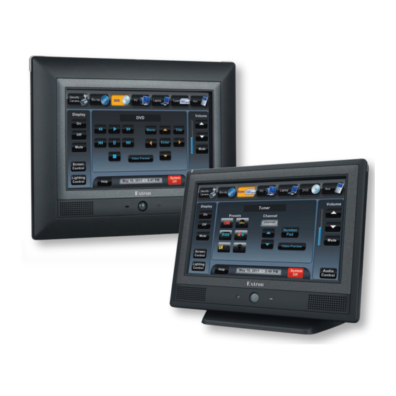
Page 10: Panel Features
Panel Features This section describes: • TLP 710MV Front Panel Features and Operations • TLP 710MV Rear Panel Features and Connections TLP 710TV Front Panel Features and Operations • • TLP 710TV Rear Panel Features and Connections TLP 710MV Front Panel Features and Operations Extron Figure 2. -
Page 11: Reset Buttons And Led
LCD screen — has a 800x480 resolution with a touch overlay. A graphical user Extron GUI Configurator software, interface, designed using the displays buttons, text, or icons on the screen (page 24). These are configured for a range of user-defined functions, using the Extron Global Configurator software (page 29). -
Page 12: Tlp 710Mv Rear Panel Features And Connections
TLP 710MV Rear Panel Features and Connections Extron Figure 5. TLP 710MV Rear Panel Features Power connector — Connect the 2-pole, 3.5 mm captive screw connector from the 12 VDC, 1.0 A power supply (not provided) to the power supply socket on the rear panel. - Page 13 CAUTIONS: • Always use a power supply supplied by or specified by Extron. Use of an unauthorized power supply voids all regulatory compliance certification and may cause damage to the supply and the end product. • Unless otherwise stated, the AC/DC adapters are not suitable for use in air handling spaces or in wall cavities.
- Page 14 Extron recommends using a Power over Ethernet (PoE) power supply. Use a straight-through Ethernet cable to connect the power supply to a switch or router. This cable carries network information from the switch or router to the power supply input. A second straight-through cable carries the network information and 48 VDC from the power supply to the TLP 710MV.
-
Page 15: Tlp 710Tv Front Panel Features And Operations
TLP 710TV Front Panel Features and Operations Extron Figure 8. TLP 710TV Front Panel Features Motion sensor — is capped with a small Fresnel lens that focuses light onto the sensor. When no motion has been detected for a user-defined period of time, the unit goes into sleep mode. -
Page 16: Tlp 710Tv Rear Panel Features And Connections
TLP 710TV Rear Panel Features and Connections The TLP 710TV has a stand that allows it to be placed on desktop. The stand can be removed to VESA mount the unit. Both the stand and the touchpanel have removable covers that conceal the rear panel features and protect cables that are attached to the TLP 710TV. - Page 17 Power connector — Connect the 2-pole, 3.5 mm captive screw connector from the 12 VDC, 1.0 A power supply (not provided) to the power supply socket on the rear panel. Ensure the connections have the correct polarity as shown in figure 10. NOTES: •...
- Page 18 Network and Power over Ethernet Connector — The TLP 710TV connects to a network using a twisted pair cable, RJ-45 Port terminated with an RJ-45 connector. The LAN port is in the Link LED top surface of the recessed area (see the arrow to the right in Activity LED figure The LAN port has two LEDs.
- Page 19 LAN Connection MTP Connection Zip-tie Cable Runway Zip-tie Figure 12. Connecting and Securing Cables VESA mounting holes — Four holes are arranged in a pattern that is in accordance with the VESA FDMI standard, type D 75 mm. See page 46 for mounting the TLP 710TV with the Extron LPVM-1 more information about (part number 60-1099-02).
-
Page 20: Initial Calibration
Initial Calibration This section describes: • Accessing the Internal On-screen Menus • Main Screen Volume Screen • • Time Screen • Network Screen • Video Screen • Touch Calibration Screen Accessing the Internal On-screen Menus When the TouchLink panel first has power applied, the unit boots up and displays the opening screen. -
Page 21: Volume Screen
The Sleep timer determines how long the panel will be inactive before it enters Sleep mode, when the screen goes dark to save power. The time can be changed from 0 to 50,000 seconds (in 10-second increments). The time that is currently selected is shown above the buttons. -
Page 22: Time Screen
Time Screen Main Month: 06 Hours: 13 Volume Down Down Time Day: 06 Minutes: 32 Network Down Down Video Year: 2011 Down Exit Figure 15. Time Screen Use the Down or Up buttons to adjust the Month, Day, Year, Hours, and Minutes. NOTE: The Hours value uses the 24-hour clock. -
Page 23: Video Screen
Video Screen Contrast: 064 Color: 064 Main Down Down Volume Time Brightness: 128 Tint: 128 Network Down Down Video Exit Figure 17. Video Screen The small gray rectangle provides a video preview window for adjusting video properties. Use the Down or Up buttons to adjust: •... -
Page 24: Configuration Software
Configuration Software This section of the user guide provides information about: • The Configuration Software • Installing the Software Using the TouchLink Panel Web Pages • • Updating the Firmware Using GUI Configurator • • Using Global Configurator The Configuration Software Designing a graphical user interface (GUI) for the TouchLink panel takes two steps: using GUI Configurator. -
Page 25: Using The Touchlink Panel Web Pages
If required, locate the Global Configurator program on the disc or website and install that also. By default, the Installer program creates and places the Global Configurator program in the C:\Program Files\Extron\GCx.x folder, where x.x represents the version of the Global Configurator program. During installation, there is an option to place an icon on the Windows desktop. - Page 26 Click the Configuration tab and select the System Settings page, which allows the user to modify the IP settings and the date and time settings. These correspond to the Network Screen (see page 16) and Time Screen (see page 16) in the on-screen menus.
-
Page 27: Updating The Firmware
Click the Touchpanel tab, which allows the user to alter the touchpanel and volume Main settings Volume settings settings. These correspond to the (see page 14) and (see page 15) in the on-screen menus. Figure 22. Touchpanel Configuration Page Updating the Firmware Extron Firmware Loader, Firmware for both touchpanels can be upgraded using the... -
Page 28: Updating Firmware Using Gui Configurator
Extron Download page, download the firmware for the TouchLink Also from the panel. Click the Firmware link on the left sidebar. Figure 23. Extron Web Page — Download Center Navigate to the TLP 710MV or TLP 710TV firmware and click Download. This downloads the firmware to your computer. -
Page 29: Updating Firmware From A Web Browser
Updating Firmware from a Web Browser Power on a computer that is connected to the same network as the TLP 710. From the Extron website (www.extron.com), download the firmware for the touchpanel. Click the Download tab on the Extron home page Select the Firmware option (see figure 23). -
Page 30: Using Gui Configurator
Using GUI Configurator This section provides an overview of the GUI Configurator program. For complete information about the program, see the GUI Configurator help file (select Contents from the Help menu or press the <F1> key while the program is running). NOTE: To configure the touchpanel, use GUI Configurator version 1.3 or later. - Page 31 Choose from the following options: Start a New Project — Clicking OK opens a dialog box that offers a choice • of project options. Figure 28. GUI Configurator New Project Dialog Box A series of icons offers the choice of creating a project with or without a template and allows the size and type of Touchlink panel to be selected.
- Page 32 Download an Existing Project from a Panel — Clicking OK opens a • dialog box that allows a file that has already been uploaded to a touchpanel to be downloaded for modification. Figure 30. GUI Configurator Download Project Dialog Box In the dialog box that opens, enter the IP address of the panel and use the Browse button to navigate to a folder where the file will be saved.
- Page 33 Depending on which option was selected in step 2, GUI Configurator opens a new or existing project. The initial screen is divided into a series of panes offering a range of tools that can be used to design or modify the project. For full details on how to use these tools, see the help file (from the Help menu select Contents or press the <F1>...
- Page 34 The project can be uploaded to one or more TouchLink panels. To add a panel: From the Project menu, select Add > Panel: Figure 32. Add a TouchLink Panel (a) The Panel Manager dialog box opens: Figure 33. Add a TouchLink Panel (b) Click the Add Panel icon to add a new panel to the left pane.
-
Page 35: Using Global Configurator
If this project has been uploaded to the TouchLink panel before, the user can upload only the changes that have been made to the previous version. The project can be uploaded to certain touchpanels selected from the list found within the Devices section of the File Upload Manager screen. - Page 36 Select Create A New Project and click OK. The dialog box closes, leaving the Project Settings screen. Figure 35. Global Configurator Project Settings Enter the IP address for the IP Link controller. The default Telnet connection is port 23 and the default HTTP connection is port 80, so these values do not usually need to be changed.
- Page 37 Click OK. The Project Settings screen closes and is replaced by the Add Device dialog box: Figure 36. Global Configurator Add Device Dialog Box Add a device to your project as follows: To see all the options, click the Advanced >>> button. The button name changes to Basic <<<...
- Page 38 Click OK. The Add Device screen closes. The start-up screen, which was behind it, is now visible, showing the IPL 250 and the available ports: Figure 37. Configuring an IP Link Device Select TouchPanel Port 1. The screen shows the available options for the TouchLink panel.
- Page 39 On the Add TouchPanel dialog box, do the following: Figure 39. Add TouchPanel Dialog Box Ensure the TouchLink panel model is selected from the drop-down menu and enter the IP address. Set the Telnet port (usually 23) and, if necessary, enter the password. Check the Import/Apply Layout check box and click OK.
-
Page 40: Specifications
Specifications TLP 710MV Display Screen type ........Active matrix TFT color display Size ..........7" (17.8 cm), measured diagonally Resolution ........800x480 Dot/pixel pitch ........ 134 dpi Aspect ratio ........Widescreen Color depth ........18 bit, 256k colors Transparency ........8 bit alpha channel Brightness ........ - Page 41 Video input — see S-video or composite video MTP transmitters or TLP VIM specifications Number/signal type ......1 S-video or composite video, as part of a set of proprietary signals Connector ........1 female RJ-45 Standards ........NTSC, PAL Audio input — see S-video or composite video MTP transmitters or TLP VIM specifications Number/signal type ......
- Page 42 Mounting Rack mount ......With optional kit Furniture or wall mount ... With included hardware Enclosure type ........ Plastic Enclosure dimensions Faceplate ......... 6.9" H x 8.7" W x 0.5" D (17.5 cm H x 22.1 cm W x 1.3 cm D) Enclosure .........
- Page 43 TLP 710TV Display Screen type ........Active matrix TFT color display Size ..........7" (17.8 cm), measured diagonally Resolution ........800x480 Dot/pixel pitch ........ 134 dpi Aspect ratio ........Widescreen Color depth ........18 bit, 256k colors Transparency ........8 bit alpha channel Brightness ........
- Page 44 Audio output Speaker output ......1 mono, 86 dB SPL, 0.1 watt, 0.1 m, half space Frequency response ......750 Hz to 20 kHz, ±5 dB Playback format(s) ......WAV files: 8 bit PCM, mono, 8 kHz sampling General Power supply ........External: Input: 100-240 VAC, 50-60 Hz Output: PoE 802.3af compliant, 48 VDC, 0.35 A, 16.8 watts Power consumption...
- Page 45 Enclosure dimensions ..... 6.1" H x 7.5" W x 7.3" D (15.5 cm H x 19.0 cm W x 18.6 cm D) (Includes base. Total height and depth depends on screen tilt. See the following diagrams.) 7.48" (19.0 cm) 75° Min. Tilt 6.10"...
-
Page 46: Accessories And Part Numbers
Accessories and Part Numbers Included Parts Description Part Number TLP 710MV TouchLink panel (wall mount, black) 60-1209-02 TLP 710MV TouchLink panel (wall mount, white) 60-1209-03 TLP 710TV TouchLink panel (desk top or VESA mount) 60-1208-02 Power over Ethernet power inserter 70-828-01 Extron removal tool Extron Software Products DVD... -
Page 47: Mounting
Mounting This section outlines the various options for: • Rack Mounting the TLP 710MV • Wall Mounting the TLP 710MV Furniture Mounting the TLP 710MV • • Wall Mounting the TLP 710MV with a Wallbox • Desktop Mounting the TLP 710TV •... -
Page 48: Wall Mounting The Tlp 710Mv
Wall Mounting the TLP 710MV The following steps show how to wall-mount theTLP 710MV. Furniture-mounting is similar. Determine the best location for the TLP 710MV. Use the template provided to mark the wall and cut a hole 10.22 inches (25.96 cm) wide by 7.16 inches (18.2 cm) high. -
Page 49: Furniture Mounting The Tlp 710Mv
Furniture Mounting the TLP 710MV The TLP 710MV can be mounted into the surface of a lectern as follows: Determine the best location for the TLP 710MV. Use the template provided to mark the lectern and cut a hole 7.5 inches (19.05 cm) wide by 5.81 inches (14.76 cm) high. -
Page 50: Wall Mounting The Tlp 710Mv With A Wall Box
Wall Mounting the TLP 710MV with a Wall Box The TLP 710MV can be wall mounted using the Extron BB 710M (part number 70-971-01) or the Extron EWB 710M (part number 70-950-0x). Follow the instructions provided with the appropriate wall box. Desktop Mounting the TLP 710TV Placement without a Mounting Kit The TLP 710TV comes assembled with a stand that allows it to be placed on a desktop. -
Page 51: Removing The Tlp 710Tv Base For Vesa Mounting
Removing the TLP 710TV Base for VESA Mounting Notch to Remove Back Cover Notch to Remove Base Cover Figure 45. Removing the Back and Base Covers Remove the back cover by inserting the Extron removal tool (provided) into the notches on each side and prying off the cover. Remove the base cover using the Extron removal tool. -
Page 52: Vesa Mounting The Tlp 710Tv
If necessary, cut the zip tie holding the twisted pair cables to the TLP 710TV base. If necessary, remove the cables from the cable runway in the base. Remove the four spanner drive security screws holding the hinges to the touchpanel. NOTE: The spanner drive screws holding the hinges require a #6 spanner bit or #6 spanner head screwdriver, which is not provided. -
Page 53: Reset Modes
Reset Modes The TLP 710MV and TLP 710TV have four reset modes that correspond to four of the five reset modes for the IP Link controllers. The modes are initiated by pressing the Reset button. To access the Reset button on the TLP 710MV, remove the bezel. See page 5 to locate the Reset button on the TLP 710MV. - Page 54 Extron Warranty Extron Electronics warrants this product against defects in materials and workmanship for a period of three years from the date of purchase; touchscreen display and overlay components are covered for 1 year. In the event of malfunction during the warranty period attributable directly to faulty workmanship and/or materials, Extron Electronics will, at...
Need help?
Do you have a question about the TouchLink TLP 710MV and is the answer not in the manual?
Questions and answers