Table of Contents
Advertisement
Quick Links
Download this manual
See also:
Installation Manual
Advertisement
Table of Contents

Related Manuals for Extron electronics TouchLink TLP 350CV


Summary of Contents for Extron electronics TouchLink TLP 350CV
- Page 1 User Guide TouchLink ® TLP 350CV and TLE 350 TouchLink 3.5" Cable Cubby Touchpanel and matching Cable Cubby Enclosure 68-1692-01 Rev. B 01 19...
- Page 2 Safety Instructions Safety Instructions • English Istruzioni di sicurezza • Italiano AVVERTENZA: Il simbolo, , se usato sul prodotto, serve ad WARNING This symbol, , when used on the product, is intended to avvertire l’utente della presenza di tensione non isolata pericolosa alert the user of the presence of uninsulated dangerous voltage within the all’interno del contenitore del prodotto che può...
- Page 3 All trademarks mentioned in this guide are the properties of their respective owners. The following registered trademarks®, registered service marks(SM), and trademarks(TM) are the property of RGB Systems, Inc. or Extron Electronics (see the current list of trademarks on the Terms of Use page at www.extron.com):...
- Page 4 FCC Class A Notice This equipment has been tested and found to comply with the limits for a Class A digital device, pursuant to part 15 of the FCC rules. The Class A limits provide reasonable protection against harmful interference when the equipment is operated in a commercial environment. This equipment generates, uses, and can radiate radio frequency energy and, if not installed and used in accordance with the instruction manual, may cause harmful interference to radio communications.
- Page 5 Conventions Used in this Guide Notifications In this user guide, the following are used: WARNING: Potential risk of severe injury or death. AVERTISSEMENT : Risque potentiel de blessure grave ou de mort. CAUTION: Risk of minor personal injury. Risque de blessure mineure. ATTENTION : ATTENTION: Risk of property damage.
-
Page 7: Table Of Contents
Contents Introduction On-screen Menus ..........19 ............1 Setup Menu ............19 About this Guide .............1 Main..............19 About the TLP 350CV ..........1 Volume ..............20 About the TLE 350 ..........2 Time ..............21 Features ..............2 IP ..............21 TLP 350CV ............2 Video ..............23 TLE 350 ..............2 Requirements for the TLP 350CV ......3 Calibration Screen ..........24 Software .............3... - Page 8 TLP 350CV and TLE 350 • Contents viii...
-
Page 9: Introduction
Introduction The touchpanels are ideal for any AV applications requiring medium or large touchpanels with flexible mounting options and fully customizable interfaces. This section provides an overview of these products: About this Guide • • About the TLP 350CV About the TLE 350 •... -
Page 10: About The Tle 350
About the TLE 350 The Extron TLE 350 Cable Cubby is a furniture-mountable enclosure that provides easy access to AV, data, and power connections. It has a low-profile design with flip-up lid and nine single- space AAP openings that can be populated with Extron AAPs and Retractors. The dimensions are identical to the TLP 350CV, making it an ideal, complementary solution for these touchpanels. -
Page 11: Requirements For The Tlp 350Cv
Requirements for the TLP 350CV Software NOTE: You must use GUI Configurator (version 1.3 or later) and Global Configurator (version 3.3 or later) to configure the TLP 350CV. Do not use GUI Designer or Global Configurator Plus and Professional. For a complete list of the requirements to run GUI Configurator or Global Configurator 3, see product page at www.extron.com for the appropriate software. -
Page 12: Installation Overview
Installation Overview Follow all these steps to mount and install the TLP 350CV. Follow steps 3 and 4 to mount the TLE 350: Before starting, download and install the latest versions of the following software: GUI Configurator — for designing layouts for Extron TouchLink touchpanels. …... - Page 13 Connect cables to the touchpanel. The unit is powered by a 12 VDC power supply. Connect the power supply (see 12 VDC External Power Supply on page 15). … ATTENTION: Do not power on the touchpanels or control processors until you have read the •...
-
Page 14: Mounting
Mounting This section describes how to mount the TLP 350CV Cable Cubby enclosure. The TLE 350 is installed in exactly the same way. The section covers covers: Planning • Tools Required for Installation • Included Parts • Ensure Adequate Under-table Clearance for Retractors •... -
Page 15: Tools Required For Installation
Tools Required for Installation Square Safety Glasses Vacuum Cleaner Marking Pen Phillips Screw Driver 1/4" Hex Nut Driver Tape Measure Figure 2. Tools Required for Installaton Included Parts Open the shipping container and verify that all the following components are present: Blank AAPs AC Power Module* Pass-thru AAPs... -
Page 16: Ensure Adequate Under-Table Clearance For Retractors
Ensure Adequate Under-table Clearance for Retractors Retractors are optional accessories for handling cables with the TLP 350CV. If you are using retractors, ensure that there is sufficient room beneath the table to accommodate them. Horizontal mounting provides maximum legroom and protects the retractors from accidental damage. - Page 17 ATTENTION: • The opening in the table for the Cable Cubby should be cut only by licensed and bonded craftspeople. Exercise care to prevent scarring or damaging the furniture. L’ouverture dans la table pour le Cable Cubby devrait être coupée seulement par •...
-
Page 18: Running Cables
Running Cables Run all cables necessary to support the AC connector, the cables stored in the cubby, and all planned AAP connectors. Run the cables below the table and through the hole that was cut in the previous step (Cutting the Surface). Leave enough slack in the cables to connect or route them before the cubby is installed in the table. -
Page 19: Installing Power Modules (Optional)
Installing Power Modules (Optional) WARNING: AVERTISSEMENT : Switch off all electrical power before connecting the AC conduit to a junction box, and • keep power off until installation is complete. Débranchez toutes les sources d’alimentation électrique avant de connecter le •... -
Page 20: Preparing And Installing The Aap Assemblies
Preparing and Installing the AAP Assemblies The AAP assembly organizes the AAPs onto a frame that can easily be inserted or removed from the TLP 350CV enclosure. Pass-through and blank AAP plates are provided with the TLP 350CV. Active or passive AAPs must be purchased separately. For the complete range of available AAPs, see www.extron.com. -
Page 21: Inserting The Aap Assemblies
Attach the AAP loosely to the bracket with the supplied #4-40 captive washer nuts. NOTE: At this time, captive washer nuts should be hand tightened; otherwise it is difficult to attach the brackets to the frame of the TLP 350CV (see Inserting the AAP Assemblies below). -
Page 22: Mounting The Enclosure
Mounting the Enclosure Mount the cable cubby enclosure in the table. CAUTION: The flanged edges of the top of the surface enclosure are sharp. These edges are also soft and may be easily nicked or bent. Exercise caution when handling the enclosure to prevent personal injury or damage to the enclosure. -
Page 23: Bottom Panel Features (Tlp 350Cv Only)
Bottom Panel Features (TLP 350CV only) NOTE: The rest of this guide applies only to the TLP 350CV (not to the TLE 350). Connect cables as described in the following section. The cable connectors are located in a panel on the bottom of the TLP 350CV: A A B B 12 VDC External Power Supply LAN Connector... -
Page 24: Power On The Tlp 350Cv
ATTENTION: • Unless otherwise stated, the AC/DC adapters are not suitable for use in air handling spaces or in wall cavities. The power supply is to be located within the same vicinity as the Extron AV processing equipment in an ordinary location, Pollution Degree 2, secured to the equipment rack within the dedicated closet, podium, or desk. -
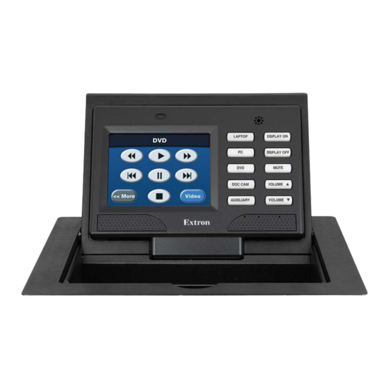
Page 25: Front Panel Features
Front Panel Features Front Panel Features With the lid closed, the screen, light sensor, and the illumination LED are disabled. They are all activated by opening the lid. Figure 12. TLP 350CV Front Panel Light sensor LCD touchscreen Speaker Configurable side buttons Menu button (under the bezel) Reset button... - Page 26 Light sensor (see figure 12 on the previous page) — monitors ambient light level. If the touchpanel is set to Autobrightness (see Auto Backlight on page 20), this value is used to calculate the amount of backlighting required for optimum viewing, allowing the screen to be read easily under different ambient lighting conditions.
-
Page 27: On-Screen Menus
On-screen Menus This section describes: Setup Menu • Calibration Screen • Setup Menu The on-screen setup menus allow basic configuration of the TLP 350CV. To open the menus, press the button on the front panel (see figure , on page 17). The menu opens on Menu the touchscreen. -
Page 28: Volume
Screen Backlight The screen backlight sets maximum touchpanel backlighting. Press the buttons to Down set a value between %. The current setting is shown just above the buttons. Auto Backlight Auto Backlight automatically adjusts the backlight depending on the ambient light detected by the front panel sensor (see figure on page 17). -
Page 29: Time
Time From the menu, press to access the menu: Main Time Time Month: 01 Hours: 17 Day: 20 Minutes: 30 Year: 2010 Main Figure 15. Time Menu Screen Use this screen to adjust the time and date settings for the touchpanel. Press the (Down) and buttons to adjust the , and... - Page 30 To change the IP address: Ensure is set to . If DHCP is set to On, the IP address is automatically provided by DHCP the system and the cannot be edited. IP Address Subnet Mask Press the on-screen IP Address box.
-
Page 31: Video
Video From the menu, press to access the menu: Main Video Contrast: 063 Color: 064 Bright: 127 Tint: 129 Main Figure 18. Video Menu Screen The video menu adjusts the appearance of a video signal connected to the video inputs. Use the buttons or the volume control knob to adjust: Contrast between... -
Page 32: Calibration Screen
Calibration Screen The touchscreen panel may require calibration to react properly to a finger touch. To access the touchpanel Calibration screen: • From the Main menu, press the recessed Menu button (figure , on page 17) once. • From any menu screen other than the screen or, if you are not in a menu screen, press Main button once, release the button and press it a second time (within one second). -
Page 33: Configuration Software
Configuration Software The section provides information on the following topics: Configuration and Control Software • Installing Software • Using the TouchLink Panel Web Pages • GUI Design and Configuration • Configuration and Control Software Designing a graphical user interface (GUI) for the TouchLink panel takes two steps: •... -
Page 34: Installing Software
Installing Software GUI Configurator and Global Configurator Installation Open a browser and go to www.extron.com. Figure 20. Extron Software Download Web Page Click ). The page opens. Download Download Click ). A selection of commonly downloaded software is shown. Software Click on the software product to go to the web page for that product. -
Page 35: Using The Touchlink Panel Web Pages
Using the TouchLink Panel Web Pages The TLP 350CV TouchLink panel has default Web pages that can be used to read and change the current settings of the panels. The Web pages can be accessed as follows: Open your browser and type the IP address of the TLP 350 unit into the address box. The browser opens the TouchLink panel page, which is read-only and provides basic Status... - Page 36 Click Passwords to set passwords for an Administrator and a User . To set a password, follow the instructions at the top of the page. Figure 24. Passwords To upgrade the unit firmware, click . More detailed instructions are found Firmware Upgrade in the Updating Firmware Using the Touchpanel Web Pages...
-
Page 37: Gui Design And Configuration
GUI Design and Configuration Using GUI Configurator This section provides an overview of the GUI Configurator program. For complete information about the program, consult the GUI Configurator Help File (select Contents in the Help Menu or press the < > key while within the program). NOTE: To configure the TLP 350CV, use GUI Configurator version 1.1 or later. - Page 38 You can choose to: Start a New Project — Clicking opens a dialog box that offers a choice of project • options. Figure 28. GUI Configurator New Project Dialog Box A series of icons offer the choice of creating a project with or without a template and allows you to select the size and type of Touchlink panel.
- Page 39 Download an Existing Project from a Panel — Clicking opens a dialog box that • allows you to download a file that has been uploaded to a panel. Figure 30. GUI Configurator Download Project Dialog Box In the dialog box that opens, enter the IP address of the panel and use the Browse...
- Page 40 To save the project, select Save Project from the File menu. The project file is saved. If this is the first time saving the project file, the dialog box appears. If the Save As Save As dialog box appears: Browse for the location where the project file is to be saved. Enter a file name for the project.
-
Page 41: Using Global Configurator
To upload a project to a TouchLink panel: From the menu, select . The Project Upload to Selected Panels Build Manager dialog box opens, showing the build progress. Once the build is complete, this dialog box closes and the File Upload Manager screen opens. - Page 42 The dialog box closes, leaving the Project Settings screen. Figure 35. Global Configurator Project Settings Enter the IP Address for the TLP 350CV panel. The default Telnet connection is port and HTTP is port , so these values do not usually need to be changed.
- Page 43 Project Settings screen closes and is replaced by the Add Device dialog box: Figure 36. Global Configurator Add Device Dialog Box To see all the options, click on the button. The button name changes to Advanced >>> (as shown in the figure above). Basic <<<...
- Page 44 Add Device screen closes. The start-up screen, which was behind it, is now visible, showing the IPL 250 and the available ports: Figure 37. Configuring an IP Link Device Select . The screen shows the available options for the TouchLink Touchpanel Port 1 panel.
- Page 45 Add TouchPanel dialog box opens. Figure 39. Add Touchpanel Dialog Box Ensure the TouchLink panel is selected from the drop-down menu and enter the Model IP address. Set the (usually ) and, if necessary, enter the password. Telnet Port Check the box and click Import/Apply Layout The window now shows the GUI from the TouchLink panel.
-
Page 46: Reference Material
Reference Material This section describes: Reset Modes • Updating Firmware • • Button Kits and Replacement Reset Modes The TLP 350CV has four reset modes that correspond to four of the five reset modes for the IP Link controllers. The reset modes are initiated by pressing the Reset button (see figure... -
Page 47: Run Or Stop Events
Run or Stop Events This mode is used for troubleshooting. Activation To start the Run/Stop Events reset mode: Press and hold the button until the Power LED blinks once (after 3 seconds). Reset Release and press momentarily (for <1 second) within 1 second. Nothing happens if Reset the momentary press does not occur within 1 second. -
Page 48: Updating Firmware
Result Reset to Factory Defaults mode performs a complete reset to factory defaults (except the firmware). Does everything Reset All IP Settings mode does. • Removes button and touchpanel user interface layout and configurations. • • Resets all touchpanel IP settings to factory default. Removes all scheduling settings. - Page 49 The Download Center for Firmware opens. Figure 42. Download Center for Firmware Click the letter from the alphabet menu (see figure 42, ). A list of the firmware for products with names beginning with the letter “T” is shown. Scroll down the page until you find the firmware for the TLP 350CV. It is listed under TouchLink Touchpanels Click for more information about the firmware.
-
Page 50: Updating Firmware Using Firmware Loader
Updating Firmware Using Firmware Loader Firmware Loader is a utility that uploads firmware from you PC to an Extron product. It is available from the Extron Website. If necessary, download and install Firmware Loader on a PC by following the procedure described in Installing Software on page 26. -
Page 51: Updating Firmware Using Gui Configurator
Updating Firmware Using GUI Configurator If necessary, download and install GUI Configurator and Firmware Loader on your PC (see Installing Software on page 26). The PC must be on the same network as the TLP 350CV. Download the firmware upgrade (see Obtaining the Latest Firmware File on page 40). -
Page 52: Button Kits And Replacement
Button Kits and Replacement Button Kits The TLP 350CV has ten dedicated, customizable function buttons to provide quick access to key functions. The buttons must be associated with their function by configuring them with Global Configurator (see the Global Configurator Help File). The unit ships with the following default set of buttons installed: Laptop Display On Display Off... - Page 53 Remove Buttons Figure 48. Button Replacement Insert the replacement buttons making sure that they are in the correct orientation. Replace the bezel that was removed in step 2. Four clips, two at the top and two at the bottom, snap into place, audibly. Reconnect the power to the touchpanel.
- Page 54 Extron Electronics makes no further warranties either expressed or implied with respect to the product and its quality, performance, merchantability, or fitness for any particular use. In no event will Extron Electronics be liable for direct, indirect, or consequential damages resulting from any defect in this product even if Extron Electronics has been advised of such damage.
Need help?
Do you have a question about the TouchLink TLP 350CV and is the answer not in the manual?
Questions and answers