Advertisement
Quick Links
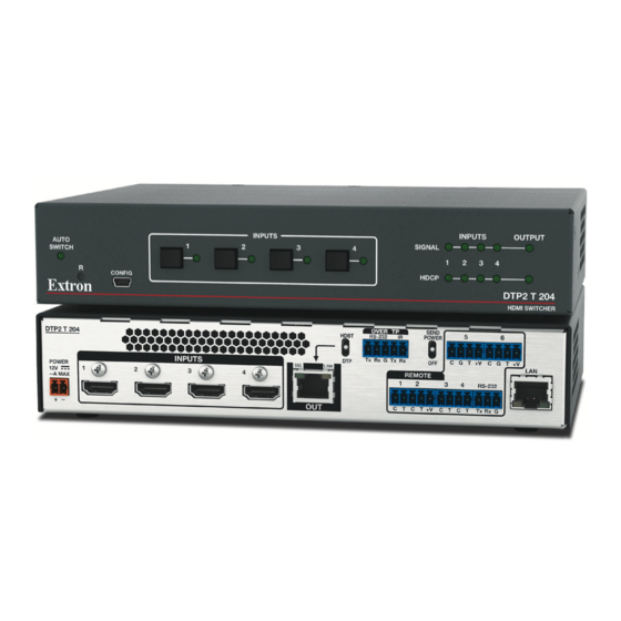
DTP2 T 204 • Setup Guide
The Extron DTP2 T 204 is an HDCP-compliant, four
input HDMI switcher with a DTP2 output that switches
and extends digital embedded audio, bidirectional
RS-232, IR, and remote power.
It supports video resolutions up to 4K @ 60 Hz and
1080p @ 120 Hz, using shielded twisted pair cabling as
a transmission medium, and extends HDMI video signals
up to 330 feet (100 meters).
The switcher features four HDMI inputs and a
DTP2/HDBT output, data rates up to 18 Gbps, HDR,
12 bit Deep Color, 3D, Lip Sync, HD lossless audio
formats, and SIS to CEC control. EDID Minder®
maintains EDID communication with connected devices
and ensures that the HDMI sources power up properly
and maintain correct video output.
Control is available via front panel buttons, USB, Extron
Product Control Software (PCS), Ethernet, RS-232,
contact closure, and auto-input switching for integration
with any control system. Front panel LED indicators provide immediate visual confirmation of HDCP authentication and signal
presence for each input and output. Remote power for the end unit is available via the DTP output.
This guide provides instructions for an experienced installer to set up and operate this switcher. For full installation,
configuration, and operation details, see the DTP T 204 User Guide, available at www.extron.com.
Rear Panel Features and Connections
DTP2 T 204
POWER
1
2
3
12V
2.2 A MAX
INPUTS
A
B
Figure 1.
DTP2 T 204 Rear Panel
Installation Steps
1.
Turn off and disconnect all of the equipment from the power source.
2.
Mount the switcher on a rack shelf or furniture (optional).
3.
Connect HDMI input sources to one or more of the DTP2 T 204 inputs (see figure 1,
present at each input and Hot Plug Detect (HPD) is actively controlled on each input.
NOTES:
•
The default (Extron) EDID is 1080p @ 60 Hz (see the DTP2 T 204 User Guide for the
EDID table).
•
LockIt
®
cable lacing brackets are provided to secure the HDMI cables to the rear panel
connectors to reduce stress on the HDMI connectors and prevent signal loss due to
loose cable connections (see the
4.
Connect the input of a DTP2 or HDBaseT compatible device to the DTP/HDBT OUT
RJ-45 connector (
C
HDBT
RS-232
Tx Rx G Tx Rx
DTP
SIG
LINK
4
OUT
C D E
LockIt Lacing Brackets
). See the image at right to wire the connector.
Extron
POWER
OVER DTP2
DTP2 R 211
12V
--A MAX
RS-232
IR
Receiver
Tx Rx
G
Tx Rx
CATx Cable
up to 330' (100 m)
Extron
DTP2 T 204
DTP2 T 204
SIG
Transmitter
POWER
1
2
3
4
12V
2.0 A MAX
INPUTS
HDMI
Extron
HDMI SM
Show Me Cables
F
I
OVER T P
SEND POWER
IR
5
6
OFF
C
C
G
T
+V
G
T
+V
REMOTE
CONT
1
2
3
4
RS-232
C
T
C
T +V
C
T C
T
Tx
Rx
G
LAN
F
G H
on page 4).
SIG
LINK
OUTPUTS
AUDIO
L
R
RS-232
DTP2 IN
HDMI
ON/OFF/MUTE Control
Extron
ON
OFF
MUTE
CCR 30
Contact Closure Remote
with Three LED Switches
OVER T P
HDBT
R S - 2 3 2
I R
SEND POWER
5
6
Ethernet
DTP
Tx Rx G Tx Rx
OFF
C
G
T
+V
C
G
T
+V
LINK
REMOTE
CONT
LAN
1
2
3
4
RS-232
C
T
C
T +V
C
T C
T
Tx
Rx
G
OUT
LAN
POWER
12V
COM 1
COM 2
COM 3
0.3A MAX
Tx Rx
G
RTS CTS
Tx Rx
G
RTS CTS
Tx Rx
A
Power input connector
B
HDMI input connectors
C
DTP/HDBT Output RJ-45 port
D
TP mode switch
E
Over TP RS-232 and IR port
F
Contact input and tally output
ports with +V connectors
G
Remote RS-232 port
H
LAN RJ-45 port
I
Remote power toggle switch
B
). The default (Extron) EDID is
Pins:
12345678
TP Wires
MODEL 80
FLAT PANEL
Flat Panel Display
Extron
IPL PRO S3
IPL Pro S3
IP Link Pro
Control Processor
G
RTS CTS
LAN / PoE
Ethernet
LAN
TIA/EIA T
568 B
Pin
Wire color
1
White-orange
Orange
2
3
White-green
4
Blue
5
White-blue
6
Green
7
White-brown
8
Brown
1
Advertisement

Subscribe to Our Youtube Channel
Related Manuals for Extron electronics DTP2 T 204


Summary of Contents for Extron electronics DTP2 T 204
- Page 1 DTP2 T 204 • Setup Guide The Extron DTP2 T 204 is an HDCP-compliant, four Extron LINK OUTPUTS MODEL 80 POWER OVER DTP2 DTP2 R 211 AUDIO input HDMI switcher with a DTP2 output that switches --A MAX RS-232 Receiver RS-232 DTP2 IN...
- Page 2 Control System next page) for USB control. RS-232 Port LAN port — To control the DTP2 T 204 through Ethernet, connect a LAN to the RJ-45 LAN connector (see figure • ). The default IP address of the scaler is 192.168.254.254, the default subnet mask is 255.255.255.0, and the default gateway address is 0.0.0.0.
- Page 3 DTP2 T 204 User Guide. • Ne branchez pas l’alimentation au DTP2 T 204 User Guide avant d’avoir lu les mises en garde « CAUTION » et «ATTENTION » aux pages 5 et 6. Power on the output display.
- Page 4 Reset button — This button initiates three modes of reset for the switcher. For the different reset levels, press and hold the button while the switcher is running or while you power up the switcher. (For more information about reset modes, see the DTP2 T 204 User Guide at www.extron.com.) LockIt Lacing Brackets Use the included LockIt lacing brackets to securely fasten the HDMI cables to each device as follows.
Need help?
Do you have a question about the DTP2 T 204 and is the answer not in the manual?
Questions and answers