
Related Manuals for H3C SecPath F10 0 Series


Summary of Contents for H3C SecPath F10 0 Series
- Page 1 H3C SecPath F10X0 Firewalls Installation Guide New H3C Technologies Co., Ltd. http://www.h3c.com Document version: 6W103-20200427...
- Page 2 The information in this document is subject to change without notice. All contents in this document, including statements, information, and recommendations, are believed to be accurate, but they are presented without warranty of any kind, express or implied. H3C shall not be liable for technical or editorial errors or omissions contained herein.
- Page 3 Preface The installation guide describes preparing for installation, installing the firewall, logging in to the firewall, hardware replacement, hardware management and maintenance, and troubleshooting. This preface includes the following topics about the documentation: • Audience. • Conventions. • Documentation feedback. Audience This documentation is intended for: •...
- Page 4 Symbols Convention Description An alert that calls attention to important information that if not understood or followed WARNING! can result in personal injury. An alert that calls attention to important information that if not understood or followed CAUTION: can result in data loss, data corruption, or damage to hardware or software. An alert that calls attention to essential information.
- Page 5 Documentation feedback You can e-mail your comments about product documentation to info@h3c.com. We appreciate your comments.
-
Page 6: Table Of Contents
Contents Preparing for installation ···································································· 1 Safety recommendations ············································································································· 1 Safety symbols ··················································································································· 1 General safety recommendations ··························································································· 1 Electrical safety ··················································································································· 2 Laser safety ······················································································································· 2 Handling safety ··················································································································· 2 Examining the installation site ······································································································· 3 ... - Page 7 Replacing an interface module ···································································································· 30 Replacing a transceiver module ·································································································· 31 Hardware management and maintenance ··········································· 32 Displaying detailed information about the firewall ············································································ 32 Displaying the software and hardware version information for the firewall ············································· 32 ...
-
Page 8: Preparing For Installation
Preparing for installation The H3C SecPath F10X0 firewall series include the following models: • F1005 • F1010 • F1020 • F1030 • F1050 • F1060 • F1070 • F1080 • F1090 NOTE: The term "hard disk" in this document refers to a drive. -
Page 9: Electrical Safety
Figure 1 Packing symbols Symbol Description Stored with a maximum stack of n units. Transported and stored with the arrows up. Transported and stored with care. Transported and stored avoiding humidity, rains and wet floor. Electrical safety • Carefully examine your work area for possible hazards such as moist floors, ungrounded power extension cables, and missing safety grounds. -
Page 10: Examining The Installation Site
• Before you move the firewall, remove all cables and mounting brackets. • For long-distance transportation, remove all the field-replaceable units (FRUs), such as power modules and interface modules, and package them separately, and install the filler panels supplied with the firewall. For short-distance transportation, make sure all the FRUs are securely seated in the slots and the screws are fastened. -
Page 11: Cooling System
Substance Concentration limit (particles/m NOTE: Dust particle diameter ≥ 5 µm The equipment room must also meet strict limits on salts, acids, and sulfides to eliminate corrosion and premature aging of components, as shown in Table Table 3 Harmful gas limits in an equipment room Max. -
Page 12: Emi
• Put the removed interface modules away on an ESD workbench, with the PCB upward, or put them in ESD bags for future use. • Always wear ESD clothing, ESD gloves, and an ESD wrist strap. Wearing an ESD wrist strap No ESD wrist strap is provided with the firewall. -
Page 13: Lightning Protection
be routed outdoors, connect a lightning arrester to the cable before you plug the cable into the port. Lightning protection To protect the firewall from lightning better, follow these guidelines: • Make sure the grounding cable of the chassis is reliably grounded. •... -
Page 14: Pre-Installation Checklist
Pre-installation checklist Table 4 Checklist before installation Item Requirements Result • There is a minimum clearance of 100 mm (3.94 in) around the inlet and outlet air vents for heat dissipation of the firewall chassis. Ventilation • A good ventilation system is available at the installation site. - Page 15 Item Requirements Result • Make sure the cabinet is equipped with a good ventilation system. • The rack is sturdy enough to support the weight of the Rack-mounting firewall and installation accessories. requirements • The size of the rack is appropriate for the firewall. •...
-
Page 16: Installing The Firewall
Keep the tamper-proof seal on a mounting screw on the chassis cover intact, and if you want to open the chassis, contact H3C for permission. Otherwise, H3C shall not be liable for any consequence. The installation procedure is the same for the H3C SecPath F1000 series firewalls. This document uses the F1080 firewall as an example. -
Page 17: Mounting The Firewall On A Workbench
Mounting the firewall on a workbench IMPORTANT: • Ensure good ventilation and a minimum clearance of 100 mm (3.94 in) around the chassis for heat dissipation. • Avoid placing heavy objects on the firewall. • To stack firewalls, make sure a minimum vertical distance of 15 mm (0.59 in) is available between two adjacent firewalls. - Page 18 CAUTION: • For adequate heat dissipation, ensure a minimum clearance of 80 mm (3.15 in) around the air inlet and outlet vents of the chassis and a distance of 1U (44.45 mm, or 1.75 in) between the chassis and other devices in the rack. •...
- Page 19 Figure 6 Attaching mounting brackets and shoulder screws to the firewall Attach the rear mounting brackets to the rear rack posts. Figure 7 Attaching the rear mounting brackets (with the wide flange inside the rack) Figure 8 Attaching the rear mounting brackets (with the wide flange outside the rack)
-
Page 20: Grounding The Firewall
Mount the firewall in the rack. Use M6 screws to secure the mounting brackets to the front rack posts and make sure the shoulder screws rest firmly on the upper edge of the rear mounting brackets. Figure 9 Mounting the firewall in the rack (with the wide flange of the rear mounting brackets inside the rack) Figure 10 Mounting the firewall in the rack (with the wide flange of the rear mounting brackets outside the rack) -
Page 21: Grounding The Firewall With A Grounding Strip
Grounding the firewall with a grounding strip If a grounding strip is available at the installation site, connect the grounding cable through the grounding strip. To connect the grounding cable: Remove the grounding screw from the firewall chassis. Attach the grounding screw to the ring terminal of the grounding cable. Use a Phillips screwdriver to fasten the grounding screw into the grounding hole on the firewall. -
Page 22: Installing Power Modules
Installing power modules CAUTION: • Make sure the power module is powered off and the grounding cable is correctly connected before installation. • Do not install both AC and DC power modules on the same firewall. • Only the F1070, F1080, and F1090 firewalls support removable power modules. Installing a power module for the F1070/F1080 Face the rear panel of the firewall. -
Page 23: Installing Optional Components
Figure 15 Removing the filler panel from the F1090 The firewall comes with the PWR1 slot empty and the PWR0 slot installed with a filler panel. Orient the power module with its handle at the right. Holding the handle of the module with one hand and supporting the module bottom with the other, slide the power module slowly into the slot along the guide rails. -
Page 24: (Optional) Installing And Removing A Hard Disk
IMPORTANT: The device does not come with any hard disks and cannot recognize hard disks from other vendors. Purchase hard disks from H3C as needed. Installing a hard disk Wear an ESD wrist strap and make sure it makes good skin contact and is reliably grounded. -
Page 25: (Optional) Installing A Lightning Arrester For A Network Port
Figure 19 Installing a hard disk NOTE: Before using the hard disk, execute the fdisk and format commands from the CLI to partition and format the hard disk. Removing a hard disk CAUTION: To avoid storage medium damage, execute the umount command from the CLI to unmount all the file systems before removing a hard disk. -
Page 26: (Optional) Installing A Lightning Arrester For An Ac Power Module
(Optional) Installing a lightning arrester for an AC power module No lightning arrester is provided with the firewall. Purchase one as needed. If part of the AC power cord is routed outdoors, install a lightning arrester to the power input end to protect the firewall from being damaged by lightning strikes. - Page 27 No transceiver module is provided with the firewall. As a best practice, use H3C transceiver modules. Figure 21 GE SFP transceiver module Figure 22 10GE SFP+ transceiver module To connect the firewall to the network through an optical fiber: Remove the dust plug from the fiber port.
-
Page 28: Connecting Power Cords
Figure 23 Installing and connecting an optical fiber Connecting power cords CAUTION: Make sure the grounding cable of the firewall is correctly connected and the power source is powered off before connecting the power cord. Connecting an AC power cord Connecting an AC power cord for an F1005 or F1010 firewall Attach the hooks of the power cord retainer clip into the holes on the top of the AC-input power receptacle, and pull the power cord retainer clip upwards. - Page 29 Connecting an AC power cord for an F1020, F1030, F1050, or F1060 firewall Connect the connector of the AC power cord to the target AC power receptacle on the rear panel of the chassis. Then use a power cord retainer clip (see Figure 25) or a cable tie (see...
-
Page 30: Connecting A Dc Power Cord
Figure 28 Connecting an AC power cord (using a cable tie to secure the power cord) Connecting an AC power cord for an F1090 firewall Connect the female connector of the AC power cord to the AC-input power receptacle on the power module. -
Page 31: Connecting A High-Voltage Dc Power Cord For An F1090 Firewall
Figure 30 Connecting a DC power cord for an F1070, F1080, or F1090 firewall Connecting a high-voltage DC power cord for an F1090 firewall Slide the cable clamp onto the tie mount, and then feed the power cord through the opening in the cable clamp. -
Page 32: Accessing The Firewall
Accessing the firewall By default, the firewall uses the scheme access authentication mode. The username and password are both admin. Setting up the configuration environment and configuring terminal parameters CAUTION: • When you connect the console cable, identify the port marks and make sure you are connecting the correct ports. -
Page 33: Starting The Firewall And Observing The Initial Startup Conditions
System is starting... Press Ctrl+D to access BASIC-BOOTWARE MENU... Press Ctrl+T to start heavy memory test Booting Normal Extended BootWare The Extended BootWare is self-decompressing..Done. **************************************************************************** H3C F1080 BootWare, Version 1.04 **************************************************************************** Compiled Date : Sep 10 2014 CPU Type : xxx... -
Page 34: Logging In To The Firewall
Known-answer test for SHA224 passed. Known-answer test for SHA256 passed. Known-answer test for SHA384 passed. Known-answer test for SHA512 passed. Known-answer test for HMAC-SHA1 passed. Known-answer test for HMAC-SHA224 passed. Known-answer test for HMAC-SHA256 passed. Known-answer test for HMAC-SHA384 passed. Known-answer test for HMAC-SHA512 passed. -
Page 35: Logging In From The Web Interface
• Logging in from the serial console port or micro USB console port • Logging in through Telnet Logging in from the Web interface IMPORTANT: After accessing the Web interface with the default account, modify the password of the default account or create a new administrator account and delete the default account as a best practice. -
Page 36: Hardware Replacement
Hardware replacement CAUTION: Wear an ESD wrist strap or ESD gloves for hardware maintenance. They are not provided with the firewall. Prepare them yourself. Replacing a power module CAUTION: • Before you replace a power module, turn off the circuit breaker and remove the power cord. •... -
Page 37: Replacing An Interface Module
Face the rear panel of the firewall. Remove the cable tie from the power cord and then remove the power cord connector from the power module. Hold the power module handle with one hand, press the latch towards the handle, and then pull the power module part way out of the slot. -
Page 38: Replacing A Transceiver Module
Figure 34 Removing an interface module Replacing a transceiver module WARNING! Disconnected optical fibers or transceiver modules might emit invisible laser light. Do not stare into beams or view directly with optical instruments when the firewall is operating. When you replace a transceiver module, make sure the two transceiver modules connected by the same optical fiber are the same type. -
Page 39: Hardware Management And Maintenance
H3C Comware Software, Version 7.1.064, Release 9313P11 Copyright (c) 2004-2017 New H3C Technologies Co., Ltd. All rights reserved. H3C SecPath F1080 uptime is 0 weeks, 0 days, 2 hours, 23 minutes Last reboot reason: User reboot Boot image: flash:/f1000fw-cmw710-boot- R9313P11.bin Boot image version: 7.1.064, Release 9313P11... -
Page 40: Displaying The Electrical Label Information For The Firewall
DEVICE_SERIAL_NUMBER : 210235A1FXH164000026 MAC_ADDRESS : 487A-DA95-91BB MANUFACTURING_DATE : 2016-04-29 VENDOR_NAME : H3C Fan 0: The operation is not supported on the specified fan. Fan 1: The operation is not supported on the specified fan. Fan 2: The operation is not supported on the specified fan. -
Page 41: Displaying The Memory Usage Of The Firewall
Table 6 Output description Field Description Slot 1 CPU 0 CPU usage CPU 0 usage information for the interface module in slot 1. Average CPU usage in the last 5 seconds. (After the firewall boots, the firewall 3% in last 5 seconds calculates and records the average CPU usage at the interval of 5 seconds.) Average CPU usage in the last minute. -
Page 42: Displaying The Operational Status Of Power Modules
Displaying the operational status of power modules Use the display power command to display the operational status of power modules. <Sysname> display power Power 0 Status: Normal Power 1 Status: Absent Table 8 Output description Field Description Power Number of the power module. Power module state: •... -
Page 43: Displaying The Operational Statistics Of The Firewall
Displaying the operational statistics of the firewall When you perform routine maintenance or the system fails, you might need to view the operational information of each functional module for locating failures. Typically you need to run display commands one by one. To collect more information one time, you can execute the display diagnostic-information command in any view to display or save the operational statistics of multiple functional modules of the firewall. -
Page 44: Rebooting The Firewall
• Power on the firewall after powering it off, which is also called hard reboot or cold start. H3C does not recommend that you use this method because it might cause data loss and hardware damages. -
Page 45: Troubleshooting
Troubleshooting Power module failure Symptom The firewall cannot be powered on, and the power LED (PWR0/PWR1) on the front panel is off. Solution To solve the issue: Power off the firewall. Verify that the power supply is as required by the firewall. Verify that the power cords of the firewall are firmly connected. -
Page 46: Cooling System Failure
If the temperature of the firewall exceeds 60°C (140°F), the following alarm information appears on the configuration terminal: %Jun 27 11:34:39:949 2017 H3C DRVMSG/3/Temp2High:Temperature Point 0/0 Too High. %Jun 27 11:34:42:557 2017 H3C DEV/4/BOARD TEMP TOOHIGH: Board temperature is too high on Chassis 0 Slot 0, type is RPU. -
Page 47: Appendix A Chassis Views And Technical Specifications
Appendix A Chassis views and technical specifications Chassis views F1005/F1010 The F1005/F1010 firewall provides the following ports on the front panel: • Eight 10/100/1000BASE-T autosensing Ethernet ports. • Two bypass ports. • Two combo interfaces. • Two USB ports. • One console port. -
Page 48: F1030/F1050/F1060
• One hard disk slot. Figure 39 Front panel (1) Hard disk slot (2) LEDs (3) 10/100/1000BASE-T copper ports (4) 1000BASE-X fiber ports (5) Console port (6) USB ports (7) Management Ethernet port (0/MGMT) Figure 40 Rear panel (1) Power receptacle (2) Interface module slot 1 (3) Interface module slot 2 (not supported) (4) Grounding screw... -
Page 49: F1070/F1080
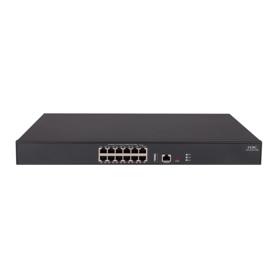
Figure 42 Rear panel (1) Power receptacle (2) Interface module slot 1 (3) Interface module slot 2 (not supported) (4) Grounding screw F1070/F1080 The F1070/F1080 firewall provides the following ports on the front panel: • Sixteen 10/100/1000BASE-T autosensing Ethernet copper ports. •... -
Page 50: F1090
F1090 The F1090 firewall provides the following ports on the front panel: • Fourteen 10/100/1000BASE-T autosensing Ethernet copper ports. • Eight 1000BASE-X fiber ports. • Eight 10GBASE-R fiber ports. • Two USB ports. • One console port. • One micro USB port. •... -
Page 51: Nsqm1Gt4Pfc
Table 10 displays the slots available for interface module installation. Table 10 Interface module and device slot compatibility Interface module F1020 F1030/F1050/F1060/F1070/F1080 F1090 NSQM1GT4PFC Slot 1 Slots 1 and 2 Slots 2 and 4 NSQM1TG4FBA Slot 1 Slots 1 and 2 Slots 2 and 4 NSQM1GP4FBA Slot 1... -
Page 52: Nsqm1Gp4Fba
(3) Ejector lever Network data encryption modules The appearance of network data encryption modules varies by models. For more information, see H3C SecPath Firewall Network Data Encryption Module Guide. Table 11 describes the hardware and software compatibility with the network data encryption modules. -
Page 53: Hard Disks
Network data Applicable firewalls and slots Applicable software version encryption module • F1090: Slots 1 through 4 • F1020: Slot 1 • F1020/F1030/F1050/F1060/F1 • F1030/F1050/F1060/F1070/F1080: 070/F1080: E9337 and later NSQM1F1KGMC Slots 1 and 2 • F1090: E8601P07 and later • F1090: Slots 1 through 4 Hard disks CAUTION:... -
Page 54: Ac Power Modules
AC power modules PSR150-A1 The PSR150-A1 power module provides a maximum output power of 150 W. Figure 51 PSR150-A1 power module (1) Handle (2) Power receptacle PSR250-12A1 The PSR250-12A1 power module provides a maximum output power of 250 W. Figure 52 PSR250-12A1 power module (1) Latch (2) Status LED (3) Handle... -
Page 55: High-Voltage Dc Power Modules
Figure 53 PSR150-D1 power module (1) Handle (2) Power receptacle PSR450-12D The PSR450-12D power module provides a maximum output power of 450 W. Figure 54 PSR450-12D power module (1) Latch (2) Status LED (3) Handle (4) Power receptacle High-voltage DC power modules CAUTION: You can install high-voltage DC power modules only on the F1090 firewall. -
Page 56: Technical Specifications
Figure 55 PSR450-12AHD power module (1) Latch (2) Status LED (3) Handle (4) Power receptacle Technical specifications Dimensions and weights Table 14 Dimensions and weights Dimensions (H × W × D), excluding rubber Weight (fully Firewall model feet and mounting brackets configured) F1005/F1010 44 ×... -
Page 57: Power Consumption
Power consumption Table 16 Power consumption Item Power consumption • F1005/F1010: 32 W • F1020/F1030/F1050/F1060: 79 W System • F1070/F1080: 116 W • F1090: 180 W NSQM1GT4PFC interface module 11.5 W NSQM1TG4FBA interface module 10.8 W NSQM1GP4FBA interface module 10.4 W NS-NIM-TG6A interface module 11 W Hard disk specifications... -
Page 58: Port Specifications
Table 20 High-voltage DC power module specifications Rated input voltage Maximum input Maximum Model range current power 100 VAC to 240 VAC @ 50 AC input 450 W Hz or 60 Hz PSR450-12AHD High-voltage DC 240 VAC to 380 VAC 3.5 A 450 W input... - Page 59 Item Specification Cable type Common asynchronous serial port cable Transmission distance ≤ 15 m (49.21 ft) • Connection to an ASCII terminal • Connection to the serial port of a local PC running the terminal Services emulation program • Micro USB console port Table 23 Micro USB console port specifications Item Specification...
- Page 60 Item Specification Transceiver module type Standard compliance 1000BASE-X Interface speed 1000 Mbps Duplex mode Full duplex Table 26 1000BASE-X SFP transceiver module specifications Central Max transmission Transceiver module Connector Fiber wavelength distance 62.5/125 µm SFP-GE-SX-MM850-A 850 nm multi-mode optical 0.55 km (1804.46 ft) fiber 9/125 µm SFP-GE-LX-SM1310-A...
- Page 61 Central Transceiver module Connector Fiber transmission wavelength distance 62.5/125 µm 82 m (269.03 ft) multi-mode optical 66 m (216.54 ft) fiber 62.5/125 µm multi-mode optical 220 m (721.78 ft) fiber SFP-XG-LX220-MM131 1310 nm 220 m (721.78 ft) 50/125 µm multi-mode optical fiber 100 m (328.08 ft) 9/125 µm single-mode...
-
Page 62: Appendix B Leds
Appendix B LEDs This section uses the LEDs on the F1080 firewall as an example. Figure 56 LEDs (1) Hard disk status LED (HD0) (2) System status LED (SYS) (3) Hard disk status LED (HD1) (4) 10/100/1000BASE-T copper port LED (5) 1000BASE-X fiber port LED (6) 10GBASE-R fiber port LED (7) Power module LED (PWR1) -
Page 63: Appendix C Cables
Appendix C Cables Console cable RJ-45 to DB9 console cable An RJ-45 to DB9 console cable is used to connect the console port on the firewall to the serial port on a configuration terminal (a PC for example): • Connect the DB9 female connector of the cable to the 8-core serial port on the configuration terminal. -
Page 64: Ethernet Twisted Pair Cable
Figure 58 Micro USB console cable Table 31 Micro USB console cable pinouts USB Type A USB Type mini-A/B Signal Signal connector connector VBUS VBUS ID(NC) Ethernet twisted pair cable Introduction An Ethernet twisted pair cable consists of four pairs of insulated copper wires twisted together. Every wire uses a different color, and has a diameter of about 1 mm (0.04 in). - Page 65 Figure 59 RJ-45 connector pinout PIN #8 PIN #1 NOTE: The RJ-45 Ethernet ports of the firewall use category 5 or higher Ethernet twisted pair cables for connection. EIA/TIA cabling specifications define two standards, 568A and 568B, for cable pinouts. •...
- Page 66 Figure 61 Crossover cable Select an Ethernet twisted pair cable according to the RJ-45 Ethernet port type on your device. An RJ-45 Ethernet port can be MDI (for routers and PCs) or MDIX (for switches). Table 33 Table 34 show their pinouts. Table 33 RJ-45 MDI port pinouts 10BASE-T/100BASE-TX 1000BASE-T...
-
Page 67: Making An Ethernet Twisted Pair Cable
10BASE-T/100BASE-TX 1000BASE-T Signal Function Signal Function Sends data BIDA- Bi-directional data cable A- Reserved BIDC+ Bi-directional data cable C+ Reserved BIDC- Bi-directional data cable C- To ensure normal communication, the pins for sending data on one port must correspond to the pins for receiving data on the peer port. - Page 68 Item Single mode fiber Multi-mode fiber Uses lasers as the light source often Uses LEDs as the light source often within Light source and within campus backbones for distance LANs or distances of a couple hundred transmission distance of several thousand meters meters within a campus network Table 36 Allowed maximum tensile force and crush load Period of force...
Need help?
Do you have a question about the SecPath F10 0 Series and is the answer not in the manual?
Questions and answers