
Related Manuals for H3C SecPath F1000-AI-X0


Summary of Contents for H3C SecPath F1000-AI-X0
- Page 1 H3C SecPath F1000-AI-X0 Firewalls Installation Guide New H3C Technologies Co., Ltd. http://www.h3c.com Document version: 6W100-20210205...
- Page 2 The information in this document is subject to change without notice. All contents in this document, including statements, information, and recommendations, are believed to be accurate, but they are presented without warranty of any kind, express or implied. H3C shall not be liable for technical or editorial errors or omissions contained herein.
- Page 3 Preface This document describes the installation procedure for the H3C SecPath F10X0 firewalls. It covers preparing for installation, installing the firewall, accessing the firewall, hardware replacement, hardware management and maintenance, and troubleshooting. This preface includes the following topics about the documentation: •...
- Page 4 Convention Description Folder. Symbols Convention Description An alert that calls attention to important information that if not understood or followed WARNING can result in personal injury. An alert that calls attention to important information that if not understood or followed CAUTION can result in data loss, data corruption, or damage to hardware or software.
- Page 5 It is normal that the port numbers, sample output, screenshots, and other information in the examples differ from what you have on your device. Documentation feedback You can e-mail your comments about product documentation to info@h3c.com. We appreciate your comments.
-
Page 6: Table Of Contents
Contents 1 Preparing for installation ············································································· 1 Safety recommendations ··································································································································· 1 Safety symbols ··········································································································································· 1 General safety recommendations ·············································································································· 1 Electrical safety ·········································································································································· 2 Laser safety ················································································································································ 2 Handling safety ·········································································································································· 2 Examining the installation site ···························································································································· 3 Weight support ··········································································································································· 3 Temperature and humidity ·························································································································... - Page 7 Replacing a power supply for an F1000-AI-60, F1000-AI-70, F1000-AI-80, or F1000-AI-90 firewall ··· 4-30 Replacing an interface module ····················································································································· 4-30 Replacing a drive ·········································································································································· 4-31 Replacing a drive for an F1000-AI-10 firewall ······················································································· 4-31 Replacing a drive for other F1000-AI-X0 firewalls than F1000-AI-10···················································· 4-32 Replacing a transceiver module ····················································································································...
- Page 8 8 Appendix B LEDs ························································································ 1 9 Appendix C Cables ·················································································· 9-1 Console cable ················································································································································· 9-1 RJ-45 to DB9 console cable ···················································································································· 9-1 Micro USB console cable ························································································································ 9-1 Ethernet twisted pair cable ······························································································································ 9-2 Introduction ············································································································································· 9-2 Making an Ethernet twisted pair cable ···································································································· 9-5 Optical fiber ·····················································································································································...
-
Page 9: Preparing For Installation
Preparing for installation This document is applicable to the following firewall models: • F1000-AI-10 • F1000-AI-20 • F1000-AI-30 • F1000-AI-50 • F1000-AI-60 • F1000-AI-70 • F1000-AI-80 • F1000-AI-90 NOTE: The term "hard disk" in this document refers to a drive. Safety recommendations To avoid any equipment damage or bodily injury, read the following safety recommendations before installation. -
Page 10: Electrical Safety
Figure1-1 Packing symbols Symbol Description Stored with a maximum stack of n units. Transported and stored with the arrows up. Transported and stored with care. Transported and stored avoiding humidity, rains and wet floor. Electrical safety • Carefully examine your work area for possible hazards such as moist floors, ungrounded power extension cables, and missing safety grounds. -
Page 11: Examining The Installation Site
• Before you move the firewall, remove all cables and mounting brackets. • For long-distance transportation, remove all the removable components, such as power supplies and interface modules, and package them separately, and install the filler panels supplied with the firewall. For short-distance transportation, make sure all the removable components are securely seated in the slots and the screws are fastened. -
Page 12: Cooling System
Substance Concentration limit (particles/m NOTE: Dust particle diameter ≥ 5 µm The equipment room must also meet strict limits on salts, acids, and sulfides to eliminate corrosion and premature aging of components, as shown in Table1-3. Table1-3 Harmful gas limits in an equipment room Max. -
Page 13: Esd Prevention
ESD prevention ESD prevention guidelines To prevent electrostatic discharge (ESD), follow these guidelines: • Make sure the firewall, the workbench, and the rack are reliably grounded. • Take dust-proof measures for the equipment room. For more information, see "Cleanliness." • Maintain the humidity and temperature at an acceptable level. -
Page 14: Lightning Protection
• Common impedance (including the grounding system) coupling. To prevent EMI, use the following guidelines: • If AC power is used, use a single-phase three-wire power receptacle with protection earth (PE) to filter interference from the power grid. • Keep the firewall far away from radio transmitting stations, radar stations, and high-frequency devices. -
Page 15: Pre-Installation Checklist
Rubber feet Power cord retainer clip Power cord Grounding cable Pre-installation checklist Table1-4 Checklist before installation Item Requirements Result • There is a minimum clearance of 100 mm (3.94 in) around the inlet and outlet air vents for heat dissipation of the firewall chassis. Ventilation •... - Page 16 Item Requirements Result • Equip a UPS. • Locate the power switch in the equipment room. In Electricity safety case of emergency during operation, switch off the power switch. • Make sure the cabinet is equipped with a good ventilation system. •...
-
Page 17: Installing The Firewall
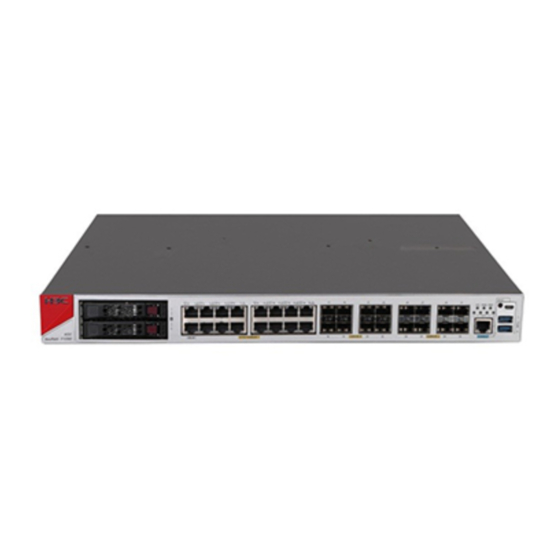
Keep the tamper-proof seal on a mounting screw on the chassis cover intact, and if you want to open the chassis, contact H3C for permission. Otherwise, H3C shall not be liable for any consequence. The firewall appearance varies by model. The following figures are for illustration only. -
Page 18: Mounting The Firewall On A Workbench
Figure2-1 Firewall installation flow Start Determine the installation position Mount the firewall on a Mount the firewall in a workbench 19-inch rack Ground the firewall Install power supplies Install interface modules Install drives Connect interface cables Connect power cords Verify the installation Mounting the firewall on a workbench IMPORTANT: •... -
Page 19: Installing The Firewall In A Standard 19-Inch Rack
To mount the firewall on a workbench: Verify that the workbench is sturdy and reliably grounded. Place the firewall upside down on the workbench and clean the four round holes in the chassis bottom with a dry cloth. Attach the four rubber feet to the round holes in the chassis bottom. Place the firewall with upside up on the workbench. - Page 20 Figure2-3 Installing cage nuts Attach the front mounting brackets to both sides of the firewall with M4 screws provided with the firewall. Figure2-4 Attaching the front mounting brackets to the firewall Mount the firewall in the rack. Use M6 screws to secure the mounting brackets to the front rack posts.
-
Page 21: Rack-Mounting The Firewall By Using Front And Rear Mounting Brackets
Rack-mounting the firewall by using front and rear mounting brackets The F1000-AI-20, F1000-AI-30, F1000-AI-50, F1000-AI-60, F1000-AI-70, F1000-AI-80, and F1000-AI-90 firewalls support this installation method. To install the firewall in a standard 19-inch rack by using front and rear mounting brackets: Wear an ESD wrist strap and make sure the wrist strap makes good skin contact and is reliably grounded. - Page 22 greater than 153 mm (6.02 in) between the rear rack posts and the interior side of the rack door. Figure2-8 Attaching the rear mounting brackets to the rear rack posts (with the wide flange inside the rack) Figure2-9 Attaching the rear mounting brackets to the rear rack posts (with the wide flange outside the rack) Mount the firewall in the rack.
-
Page 23: Grounding The Firewall
Figure2-11 Mounting the firewall in the rack (with the wide flange of the rear mounting brackets outside the rack) Grounding the firewall WARNING! • Correctly connecting the firewall grounding cable is crucial to lightning protection and EMI protection. • Do not connect the firewall grounding cable to a fire main or lightning rod. You can ground the firewall in one of the following ways, depending on the grounding conditions available at the installation site. -
Page 24: Grounding The Firewall With The Grounding Terminal On The Rack
Figure2-12 Grounding the firewall with a grounding strip Grounding the firewall with the grounding terminal on the rack Remove the grounding screw from the firewall chassis. Attach the grounding screw to the ring terminal of the grounding cable. Use a Phillips screwdriver to fasten the grounding screw into the grounding hole on the firewall. Remove the grounding screw from the grounding point on the rack. -
Page 25: Installing A Power Supply For An F1000-Ai-60, F1000-Ai-70, F1000-Ai-80, Or F1000-Ai-90 Firewall
The firewall comes with the PWR1 slot empty and the PWR0 slot installed with a filler panel. Figure2-14 Removing the filler panel from an F1000-AI-20, F1000-AI-30, or F1000-AI-50 firewall Orient the power supply with its handle at the left. Holding the handle of the module with one hand and supporting the module bottom with the other, slide the power supply slowly into the slot along the guide rails. -
Page 26: Installing An Interface Module
Orient the power supply with its handle at the right. Holding the handle of the module with one hand and supporting the module bottom with the other, slide the power supply slowly into the slot along the guide rails. Figure2-17 Installing a power supply for an F1000-AI-60, F1000-AI-70, F1000-AI-80, or F1000-AI-90 firewall Installing an interface module CAUTION:... -
Page 27: Installing A Drive
• Install a filler panel in empty drive slots to prevent dust and ESD damage. IMPORTANT: • The device does not come with any drives and cannot recognize drives from other vendors. Purchase drives from H3C as needed. • Before using the drive, execute the commands from the CLI to partition and... -
Page 28: Connecting Ethernet Cables
Remove the filler panel from the drive slot. Press the button on the drive panel to release the locking lever. Hold the locking lever and push the drive into the slot slowly along the guide rails. Then close the locking lever. Figure2-21 Installing a drive for other firewalls than the F1000-AI-10 Connecting Ethernet cables Connecting a copper Ethernet port... - Page 29 The firewall supports GE SFP transceiver modules and 10GE SFP+ transceiver modules. For the transceiver module specifications, see "GE fiber Ethernet port" and "10 GE fiber Ethernet port." No transceiver module is provided with the firewall. As a best practice, use H3C transceiver modules.
-
Page 30: Connecting Power Cords
Figure2-24 Installing and connecting an optical fiber Connecting power cords CAUTION: Make sure the grounding cable of the firewall is correctly connected and the power source is powered off before connecting the power cord. Connecting an AC power cord Connecting an AC power cord for an F1000-AI-10 firewall Attach the hooks of the power cord retainer clip into the holes on the top of the AC-input power receptacle, and pull the power cord retainer clip upwards. - Page 31 Connecting an AC power cord for an F1000-AI-20, F1000-AI-30, or F1000-AI-50 firewall Connect the connector of the AC power cord to the target AC power receptacle on the rear panel of the chassis. Then use a power cord retainer clip (see Figure2-26) or a releasable cable tie (see Figure2-27) to secure the power cord.
-
Page 32: Connecting A Dc Power Cord
Connecting a DC power cord Correctly orient the DC power cord connector with the power receptacle on the power supply, and insert the connector into the receptacle. The receptacle is foolproof. If you cannot insert the connector into the receptacle, re-orient the connector rather than use excessive force to push it in. -
Page 33: Accessing The Firewall
Accessing the firewall By default, the firewall uses the scheme access authentication mode. The username and password are both admin. Setting up the configuration environment and configuring terminal parameters CAUTION: • When you connect the console cable, identify the port marks and make sure you are connecting the correct ports. -
Page 34: Starting The Firewall And Observing The Initial Startup Conditions
System is starting... Press Ctrl+D to access BASIC-BOOTWARE MENU... Press Ctrl+T to start heavy memory test Booting Normal Extended BootWare The Extended BootWare is self-decompressing..Done. **************************************************************************** H3C BootWare, Version 2.00 **************************************************************************** Compiled Date : Sep 10 2018 CPU Type : xxx... -
Page 35: Logging In To The Firewall
Known-answer test for SHA1 passed. Known-answer test for SHA224 passed. Known-answer test for SHA256 passed. Known-answer test for SHA384 passed. Known-answer test for SHA512 passed. Known-answer test for HMAC-SHA1 passed. Known-answer test for HMAC-SHA224 passed. Known-answer test for HMAC-SHA256 passed. Known-answer test for HMAC-SHA384 passed. -
Page 36: Logging In From The Web Interface
• Logging in from the Web interface • Logging in from the serial console port or micro USB console port • Logging in through Telnet Logging in from the Web interface IMPORTANT: After accessing the Web interface with the default account, modify the password of the default account or create a new administrator account and delete the default account as a best practice. -
Page 37: Hardware Replacement
Hardware replacement CAUTION: Wear an ESD wrist strap or ESD gloves for hardware maintenance. They are not provided with the firewall. Prepare them yourself. Replacing a power supply CAUTION: • Before you replace a power supply, turn off the circuit breaker and remove the power cord. •... -
Page 38: Replacing A Power Supply For An F1000-Ai-60, F1000-Ai-70, F1000-Ai-80, Or F1000-Ai-90 Firewall
Replacing a power supply for an F1000-AI-60, F1000-AI-70, F1000-AI-80, or F1000-AI-90 firewall The replacement procedure is the same for an AC power supply and a DC power supply. This section takes an AC power supply as an example. To replace a power supply for an F1000-AI-60, F1000-AI-70, F1000-AI-80, or F1000-AI-90 firewall: Face the rear panel of the firewall. -
Page 39: Replacing A Drive
Put the removed interface module (with the circuit board facing upward) on an antistatic workbench or into an antistatic bag. Install a new interface module. For the installation procedure, see "Installing an interface module." If you are not to install a new interface module, install a filler panel in the slot to ensure good ventilation in the firewall. -
Page 40: Replacing A Drive For Other F1000-Ai-X0 Firewalls Than F1000-Ai-10
Replacing a drive for other F1000-AI-X0 firewalls than F1000-AI-10 Wear an ESD wrist strap and make sure it makes good skin contact and is reliably grounded. Press the button on the drive panel to release the locking lever. Hold the locking lever and pull the drive out of the slot. Install a new drive. - Page 41 Figure4-7 Removing the transceiver module Install dust caps to the removed transceiver module, and put it into the package. Install a new transceiver module. If you do not install a new transceiver module in the slot, install a dust cap. For information about installing a transceiver module, see "Connecting a fiber port."...
-
Page 42: Hardware Management And Maintenance
<Sysname> display version H3C Comware Software, Version 7.1.064, Ess 9345 Copyright (c) 2004-2019 New H3C Technologies Co., Ltd. All rights reserved. H3C SecPath F1000-AI-50 uptime is 0 weeks, 3 days, 1 hour, 3 minutes Last reboot reason: User reboot Boot image: flash:/f1000fw-cmw710-boot-E9345.bin Boot image version: 7.1.064, Ess 9345... -
Page 43: Displaying The Cpu Usage Of The Firewall
DEVICE_SERIAL_NUMBER : 210235A3DDH1000028 MAC_ADDRESS : 487A-DA95-91F3 MANUFACTURING_DATE : 2019-04-29 VENDOR_NAME : H3C Fan 0: The operation is not supported on the specified fan. Fan 1: The operation is not supported on the specified fan. Fan 2: The operation is not supported on the specified fan. -
Page 44: Displaying The Memory Usage Of The Firewall
Slot 1 CPU 0 CPU usage: 3% in last 5 seconds 3% in last 1 minute 3% in last 5 minutes Table5-2 Output description Field Description Slot 1 CPU 0 CPU usage CPU 0 usage information for the interface module in slot 1. Average CPU usage in the last 5 seconds. -
Page 45: Displaying The Operational Status Of Power Supplies
Field Description which indicates the physical memory available for applications. Swap Swap memory. Displaying the operational status of power supplies Use the command to display the operational status of power supplies. display power <Sysname> display power Power 0 Status: Normal Power 1 Status: Absent Table5-4 Output description... -
Page 46: Displaying The Operational Statistics Of The Firewall
Field Description LowerLimit Low temperature alarm threshold. Warning-UpperLimit Warning-level high temperature alarm threshold. Alarm-UpperLimit Alarm-level high temperature alarm threshold. Shutdown-level high temperature alarm threshold. The firewall automatically Shutdown-Upperlimit powers off when the temperature exceeds this threshold. Displaying the operational statistics of the firewall When you perform routine maintenance or the system fails, you might need to view the operational information of each functional module for locating failures. -
Page 47: Rebooting The Firewall
• Power on the firewall after powering it off, which is also called hard reboot or cold start. H3C does not recommend that you use this method because it might cause data loss and hardware damages. - Page 48 Task Command Remarks and specify a reboot waiting time: scheduler reboot delay 5-40...
-
Page 49: Troubleshooting
Troubleshooting Power supply failure Symptom The firewall cannot be powered on, and the power LED (PWR0/PWR1) on the front panel is off. Solution To solve the issue: Power off the firewall. Verify that the power supply is as required by the firewall. Verify that the power cords of the firewall are firmly connected. -
Page 50: Cooling System Failure
If the temperature of the firewall exceeds 60°C (140°F), the following alarm information appears on the configuration terminal: %Jun 27 11:34:39:949 2017 H3C DRVMSG/3/Temp2High:Temperature Point 0/0 Too High. %Jun 27 11:34:42:557 2017 H3C DEV/4/BOARD TEMP TOOHIGH: Board temperature is too high on Chassis 0 Slot 0, type is RPU. -
Page 51: Appendix A Chassis Views And Technical Specifications
Appendix A Chassis views and technical specifications Chassis views F1000-AI-10 The F1000-AI-10 firewall provides the following ports on the front panel: • Eighteen 10/100/1000BASE-T autosensing Ethernet copper ports. • Two 10GBASE-R fiber ports. • Two management Ethernet ports. • Four bypass ports. •... -
Page 52: F1000-Ai-20/F1000-Ai-30/F1000-Ai-50
Figure7-2 Rear panel (1) Power receptacle (2) Grounding screw F1000-AI-20/F1000-AI-30/F1000-AI-50 The F1000-AI-20/F1000-AI-30/F1000-AI-50 firewall provides the following ports on the front panel: • Fifteen 10/100/1000BASE-T autosensing Ethernet copper ports. • Eight 1000BASE-X fiber ports. • Two 10GBASE-R fiber ports. • Two USB ports. •... -
Page 53: F1000-Ai-60
F1000-AI-60 The F1000-AI-60 firewall provides the following ports on the front panel: • Fourteen 10/100/1000BASE-T autosensing Ethernet copper ports. • Twelve 1000BASE-X fiber ports. • Four 10GBASE-R fiber ports. • Two USB ports. • One console port. • One micro USB port. •... -
Page 54: F1000-Ai-80/F1000-Ai-90
• Four 10GBASE-R fiber ports. • Two USB ports. • One console port. • One micro USB port. • Two drive slots. • Two management Ethernet ports. Figure7-7 Front panel (1) Hard disk slots (2) Management Ethernet port (0/MGMT) (3) 10/100/1000BASE-T copper ports (4) 1000BASE-X fiber ports (5) 10GBASE-R fiber ports (6) 1000BASE-X fiber ports... -
Page 55: Interface Modules
• Two management Ethernet ports. Figure7-9 Front panel (1) Hard disk slots (2) Management Ethernet port (0/MGMT) (3) 10/100/1000BASE-T copper ports (4) 10GBASE-R fiber ports (5) 1000BASE-X fiber ports (6) LEDs (7) Reset button (8) Micro USB port (9) USB ports (10) Console port (11) Management Ethernet port (1/MGMT) Figure7-10 Rear panel... -
Page 56: Nsqm1Gp4Fba
F1000-AI-70/ Interface F1000-AI-20/F1000-AI F1000-AI-10 F1000-AI-60 F1000-AI-80/ module -30/F1000-AI-50 F1000-AI-90 NS-NIM-TG6A Not supported Not supported Slot 1 Slots 1 and 3 NSQM1GT4PFC The NSQM1GT4PFC interface module provides four 10/100/1000BASE-T Ethernet copper ports. • When the firewall is operating correctly, the four ports operate as common data ports. •... -
Page 57: Ns-Nim-Tg6A
The network data encryption modules are not hot swappable. The appearance of network data encryption modules varies by models. For more information, see H3C SecPath Firewall Network Data Encryption Module Guide. Table7-2 describes the network data encryption module compatibility with the firewalls and software. -
Page 58: Power Supplies
Network data Applicable firewalls and slots Applicable software version encryption module • • F1000-AI-60: Slots 1 and 2 F1000-AI-60: E8601P07 and later • • F1000-AI-70/F1000-AI-80/F1000-AI- F1000-AI-70/F1000-AI-80/F1000-AI 90: Slots 1 to 4 -90: E8601P07 and later • • F1000-AI-20/F1000-AI-30/F1000-AI- F1000-AI-20/F1000-AI-30/F1000-AI 50: Slots 1 and 2 -50: E9337 and later NSQM1F1KGM •... -
Page 59: Dc Power Supplies
Figure7-15 PSR150-A1 power supply (1) Handle (2) Power receptacle PSR250-12A1 The PSR250-12A1 power supply provides a maximum output power of 250 W. Figure7-16 PSR250-12A1 power supply (1) Latch (2) Status LED (3) Handle (4) Power receptacle DC power supplies PSR150-D1 The PSR150-D1 power supply provides a maximum output power of 150 W. -
Page 60: High-Voltage Dc Power Supplies
Figure7-17 PSR150-D1 power supply (1) Handle (2) Power receptacle PSR450-12D The PSR450-12D power supply provides a maximum output power of 450 W. Figure7-18 PSR450-12D power supply (1) Latch (2) Status LED (3) Handle (4) Power receptacle High-voltage DC power supplies CAUTION: You can install high-voltage DC power supplies only on the F1000-AI-60, F1000-AI-70, F1000-AI-80, and F1000-AI-90 firewalls. -
Page 61: Dimensions And Weights
Figure7-19 PSR450-12AHD power supply (1) Latch (2) Status LED (3) Handle (4) Power receptacle Dimensions and weights The weight of the firewall includes the chassis and its removable components. Chassis Table7-4 Chassis dimensions and weights Dimensions (H × W × D), Weight (fully Firewall model excluding rubber feet and... -
Page 62: Network Data Encryption Modules
Network data encryption modules Table7-6 Network data encryption module dimensions and weights Network data encryption module Dimensions (H × W × D) Weight model NSQM1F1KGM0 40.1 × 150 × 172.9 mm (1.58 × 5.91 × 6.81 in) 0.64 kg (1.41 lb) NSQM1F1KGMB 19.8 ×... -
Page 63: Network Data Encryption Modules
NSQM1TG4FBA 10.8 W NSQM1GP4FBA 10.4 W NS-NIM-TG6A 11 W Network data encryption modules Table7-10 Network data encryption module power consumption Network data encryption module model Power consumption NSQM1F1KGM0 4.14 W NSQM1F1KGMB 3.7 W NSQM1F1KGMC 5.7 W Power supply specifications Table7-11 AC power supply specifications Maximum input Maximum Model... -
Page 64: Port Specifications
Port specifications Console port Table7-14 Console port specifications Item Specification Connector RJ-45 Standard compliant RS-232 Baud rate 9600 bps (default) to 115200 bps Cable type Common asynchronous serial port cable ≤ 15 m (49.21 ft) Transmission distance • Connection to an ASCII terminal •... -
Page 65: 10 Ge Fiber Port
Item Specification 100 Mbps, half/full-duplex 1000 Mbps, full-duplex NOTE: The media dependent interface (MDI) standard is typically used on the Ethernet port of network adapters. The media dependent interface crossover (MDI-X) standard is typically used on hubs or LAN switches. GE fiber port Table7-17 GE fiber port specifications Item... - Page 66 Table7-20 10 Gbps SFP+ transceiver module specifications Central Cable Connector Transceiver module wavelength specifications transmission type (nm) (µm) distance 50/125, MMF 300 m (984.3 ft) SFP-XG-SX-MM850-A 82 m (269.03 ft) 62.5/125, MMF 66 m (216.54 ft) 62.5/125, MMF 220 m (721.78 ft) SFP-XG-LX220-MM131 1310 220 m (721.78 ft)
-
Page 67: Appendix B Leds
Appendix B LEDs The firewalls use similar LEDs. This section uses the LEDs on the F1000-AI-50 firewall as an example. Figure8-1 LEDs (1) Ethernet copper port LED (2) Ethernet fiber port LED (3) System status LED (4) Power supply status LED (5) Interface module status LED Table8-2 LED description Mark... -
Page 68: Appendix C Cables
Appendix C Cables Console cable RJ-45 to DB9 console cable An RJ-45 to DB9 console cable is used to connect the console port on the firewall to the serial port on a configuration terminal (a PC for example): • Connect the DB9 female connector of the cable to the 8-core serial port on the configuration terminal. -
Page 69: Ethernet Twisted Pair Cable
Figure9-2 Micro USB console cable Type A connector Type B connector Table9-2 Micro USB console cable pinouts USB Type A USB Type mini-A/B Signal Signal connector connector VBUS VBUS ID(NC) Ethernet twisted pair cable Introduction An Ethernet twisted pair cable consists of four pairs of insulated copper wires twisted together. Every wire uses a different color, and has a diameter of about 1 mm (0.04 in). - Page 70 Figure9-3 RJ-45 connector pinout PIN #8 PIN #1 NOTE: The RJ-45 Ethernet ports of the firewall use category 5 or higher Ethernet twisted pair cables for connection. EIA/TIA cabling specifications define two standards, 568A and 568B, for cable pinouts. • Standard 568A—pin 1: white/green stripe, pin 2: green solid, pin 3: white/orange stripe, pin 4: blue solid, pin 5: white/blue stripe, pin 6: orange solid, pin 7: white/brown stripe, pin 8: brown solid.
- Page 71 Figure9-5 Crossover cable white/orange orange white/green blue white/blue green white/brown brown Crossover cable white/green green white/orange blue white/blue orange white/brown brown Select an Ethernet twisted pair cable according to the RJ-45 Ethernet port type on your device. An RJ-45 Ethernet port can be MDI (for routers and PCs) or MDIX (for switches). Table9-4 Table9-5 show their pinouts.
-
Page 72: Making An Ethernet Twisted Pair Cable
10BASE-T/100BASE-TX 1000BASE-T Signal Function Signal Function Sends data BIDA- Bi-directional data cable A- Reserved BIDC+ Bi-directional data cable C+ Reserved BIDC- Bi-directional data cable C- To ensure normal communication, the pins for sending data on one port must correspond to the pins for receiving data on the peer port. - Page 73 Item Single mode fiber Multi-mode fiber transmission distance within campus backbones for distance LANs or distances of a couple hundred of several thousand meters meters within a campus network Table9-7 Allowed maximum tensile force and crush load Period of force Tensile load (N) Crush load (N/mm) Short period...
Need help?
Do you have a question about the SecPath F1000-AI-X0 and is the answer not in the manual?
Questions and answers