
Related Manuals for H3C SecPath F10X0


Summary of Contents for H3C SecPath F10X0
- Page 1 H3C SecPath F10X0 Firewalls Installation Guide New H3C Technologies Co., Ltd. http://www.h3c.com Document version: 6W105-20220215...
- Page 2 The information in this document is subject to change without notice. All contents in this document, including statements, information, and recommendations, are believed to be accurate, but they are presented without warranty of any kind, express or implied. H3C shall not be liable for technical or editorial errors or omissions contained herein.
- Page 3 Preface This document describes the installation procedure for the H3C SecPath F10X0 firewalls. It covers preparing for installation, installing the firewall, logging in to the firewall, hardware replacement, hardware management and maintenance, and troubleshooting. This preface includes the following topics about the documentation: •...
- Page 4 Convention Description Folder. Symbols Convention Description An alert that calls attention to important information that if not understood or followed WARNING can result in personal injury. An alert that calls attention to important information that if not understood or followed CAUTION can result in data loss, data corruption, or damage to hardware or software.
- Page 5 It is normal that the port numbers, sample output, screenshots, and other information in the examples differ from what you have on your device. Documentation feedback You can e-mail your comments about product documentation to info@h3c.com. We appreciate your comments.
-
Page 6: Table Of Contents
Contents 1 Preparing for installation ············································································· 1 Safety recommendations ··································································································································· 1 Safety symbols ··········································································································································· 1 General safety recommendations ·············································································································· 1 Electrical safety ·········································································································································· 2 Laser safety ················································································································································ 2 Handling safety ·········································································································································· 2 Examining the installation site ···························································································································· 3 Weight support ··········································································································································· 3 Temperature and humidity ·························································································································... - Page 7 Replacing an interface module ····················································································································· 4-31 Replacing a drive ·········································································································································· 4-32 Replacing a transceiver module ···················································································································· 4-32 5 Hardware management and maintenance ············································· 5-34 Displaying detailed information about the firewall ························································································· 5-34 Displaying the software and hardware version information for the firewall ··················································· 5-34 Displaying the electrical label information for the firewall··············································································...
- Page 8 Ethernet twisted pair cable ···························································································································· 9-59 Introduction ··········································································································································· 9-59 Making an Ethernet twisted pair cable ·································································································· 9-62 Optical fiber ··················································································································································· 9-63...
-
Page 9: Preparing For Installation
Preparing for installation The H3C SecPath F10X0 firewall series include the following models: • F1005 • F1010 • F1020 • F1030 • F1050 • F1060 • F1070 • F1080 • F1090 Safety recommendations To avoid any equipment damage or bodily injury, read the following safety recommendations before installation. -
Page 10: Electrical Safety
Figure1-1 Packing symbols Symbol Description Stored with a maximum stack of n units. Transported and stored with the arrows up. Transported and stored with care. Transported and stored avoiding humidity, rains and wet floor. Electrical safety • Carefully examine your work area for possible hazards such as moist floors, ungrounded power extension cables, and missing safety grounds. -
Page 11: Examining The Installation Site
• Before you move the firewall, remove all cables and mounting brackets. • For long-distance transportation, remove all removable components, such as power modules and interface modules, and package them separately, and install the filler panels supplied with the firewall. For short-distance transportation, make sure all removable components are securely seated in the slots and the screws are fastened. -
Page 12: Cooling System
Substance Concentration limit (particles/m NOTE: Dust particle diameter ≥ 5 µm The equipment room must also meet strict limits on salts, acids, and sulfides to eliminate corrosion and premature aging of components, as shown in Table1-3. Table1-3 Harmful gas limits in an equipment room Max. -
Page 13: Emi
• Maintain the humidity and temperature at an acceptable level. For more information, see "Temperature and humidity." • Put the removed interface modules away on an ESD workbench, with the PCB upward, or put them in ESD bags for future use. •... -
Page 14: Installation Tools
Installation tools All installation tools are user supplied. Flat-head screwdriver Phillips screwdriver Needle-nose pliers Diagonal pliers ESD wrist strap Marker Accessories M6 rack screw and cage nut Mounting bracket Mounting brackets (including M4 (shipped with the F1005 for the F1005 and shoulder screw) for other F10X0 M4 screw and F1010 firewalls and... - Page 15 Item Requirements Result • Operating: Without drives: 0°C to 45°C (32°F to 113°F) Temperature With drives: 5°C to 40°C (41°F to 104°F) • Storage: –40°C to +70°C (–40°F to +158°F) • Operating: Without drives: 5% RH to 95% RH, ...
- Page 16 Item Requirements Result • accessories User-supplied tools • Documents shipped with the firewall Reference • Online documents...
-
Page 17: Installing The Firewall
Keep the tamper-proof seal on a mounting screw on the chassis cover intact, and if you want to open the chassis, contact H3C for permission. Otherwise, H3C shall not be liable for any consequence. The firewall view varies by model. The following figures are for illustration only. This document uses an F1080 firewall as an example. -
Page 18: Installing The Firewall In A Standard 19-Inch Rack
If a standard 19-inch rack is not available, you can place the firewall on a workbench. To mount the firewall on a workbench: Verify that the workbench is sturdy and reliably grounded. Place the firewall upside down on the workbench and clean the four round holes in the chassis bottom with a dry cloth. - Page 19 Wear an ESD wrist strap and make sure the wrist strap makes good skin contact and is reliably grounded. Unpack the firewall and accessories. Mark the cage nut installation positions on the rack posts by using the mounting brackets. Use a front mounting bracket to mark the positions on the front rack posts and use a rear mounting bracket to mark the positions on the rear rack posts.
- Page 20 Distance between the front and rear rack Rear mounting bracket installation posts method door. Figure2-4 Attaching the rear mounting brackets (with the wide flange inside the rack) Figure2-5 Attaching the rear mounting brackets (with the wide flange outside the rack) Mount the firewall in the rack.
-
Page 21: Rack-Mounting The Firewall By Using Front Mounting Brackets
Figure2-6 Mounting the firewall in the rack (with the wide flange of the rear mounting brackets inside the rack) Figure2-7 Mounting the firewall in the rack (with the wide flange of the rear mounting brackets outside the rack) Rack-mounting the firewall by using front mounting brackets The F1005 and F1010 firewalls support this installation method. - Page 22 Figure2-8 Installing cage nuts Attach the front mounting brackets to both sides of the firewall with M4 screws provided with the firewall. Figure2-9 Attaching the front mounting brackets to the firewall Mount the firewall in the rack. Use M6 screws to secure the mounting brackets to the front rack posts.
-
Page 23: Grounding The Firewall
Figure2-10 Mounting the firewall in the rack Grounding the firewall WARNING! • Correctly connecting the firewall grounding cable is crucial to lightning protection and EMI protection. • Do not connect the firewall grounding cable to a fire main or lightning rod. You can ground the firewall in one of the following ways, depending on the grounding conditions available at the installation site. -
Page 24: Grounding The Firewall With The Grounding Terminal On The Rack
Figure2-11 Grounding the firewall with a grounding strip Grounding the firewall with the grounding terminal on the rack Remove the grounding screw from the firewall chassis. Attach the grounding screw to the ring terminal of the grounding cable. Use a Phillips screwdriver to fasten the grounding screw into the grounding hole on the firewall. Remove the grounding screw from the grounding point on the rack. -
Page 25: Installing A Power Module For An F1090 Firewall
Remove the filler panel (if any) from the target power module slot. Figure2-13 Removing the filler panel from an F1070 or F1080 firewall The firewall comes with the PWR1 slot empty and the PWR0 slot installed with a filler panel. Orient the power module with its handle at the left. -
Page 26: Installing An Interface Module
The firewall comes with the PWR1 slot empty and the PWR0 slot installed with a filler panel. Orient the power module with its handle at the right. Holding the handle of the module with one hand and supporting the module bottom with the other, slide the power module slowly into the slot along the guide rails. -
Page 27: Installing A Drive
The device does not come with any drives and cannot recognize drives from other vendors. Purchase drives from H3C as needed. To install a drive: Wear an ESD wrist strap and make sure it makes good skin contact and is reliably grounded. -
Page 28: Connecting A Fiber Port
The firewall supports GE SFP transceiver modules and 10GE SFP+ transceiver modules. For the transceiver module specifications, see "GE fiber Ethernet port" and "10 GE fiber Ethernet port." No transceiver module is provided with the firewall. As a best practice, use H3C transceiver modules. -
Page 29: Connecting Power Cords
Figure2-21 10GE SFP+ transceiver module To connect the firewall to the network through an optical fiber: Remove the dust plug from the fiber port. Remove the dust cap from the transceiver module and insert it into the fiber port. Remove the dust cap of the optical fiber connector, and use dust free paper and absolute alcohol clean the end face of the fiber connector. -
Page 30: Connecting An Ac Power Cord
Connecting an AC power cord Connecting an AC power cord for an F1005 or F1010 firewall Attach the hooks of the power cord retainer clip into the holes on the top of the AC-input power receptacle, and pull the power cord retainer clip upwards. Connect one end of the AC power cord to the AC-input power receptacle on the firewall. - Page 31 Figure2-25 Connecting an AC power cord (using a cable tie to secure the power cord) Connecting an AC power cord for an F1070 or F1080 firewall Connect the connector of the AC power cord to the AC power receptacle on the rear panel of the chassis.
-
Page 32: Connecting A Dc Power Cord
Figure2-28 Connecting an AC power cord for an F1090 firewall Connecting a DC power cord Connecting a DC power cord for an F1070, F1080, or F1090 firewall Correctly orient the DC power cord connector with the power receptacle on the power module, and insert the connector into the receptacle. - Page 33 • There is enough space for heat dissipation around the firewall. • The firewall and its components are installed securely. The screws are fastened tightly. • The power source specifications are as required by the firewall. • The grounding cable and power cords are connected correctly.
-
Page 34: Accessing The Firewall
Accessing the firewall By default, the firewall uses the scheme access authentication mode. The username and password are both admin. Setting up the configuration environment and configuring terminal parameters CAUTION: • When you connect the console cable, identify the port marks and make sure you are connecting the correct ports. -
Page 35: Starting The Firewall And Observing The Initial Startup Conditions
System is starting... Press Ctrl+D to access BASIC-BOOTWARE MENU... Press Ctrl+T to start heavy memory test Booting Normal Extended BootWare The Extended BootWare is self-decompressing..Done. **************************************************************************** H3C F1080 BootWare, Version 1.04 **************************************************************************** Compiled Date : Sep 10 2014 CPU Type : xxx... -
Page 36: Logging In To The Firewall
Known-answer test for SHA224 passed. Known-answer test for SHA256 passed. Known-answer test for SHA384 passed. Known-answer test for SHA512 passed. Known-answer test for HMAC-SHA1 passed. Known-answer test for HMAC-SHA224 passed. Known-answer test for HMAC-SHA256 passed. Known-answer test for HMAC-SHA384 passed. Known-answer test for HMAC-SHA512 passed. -
Page 37: Logging In From The Web Interface
• Logging in from the serial console port or micro USB console port • Logging in through Telnet Logging in from the Web interface IMPORTANT: After accessing the Web interface with the default account, modify the password of the default account or create a new administrator account and delete the default account as a best practice. -
Page 38: Hardware Replacement
Hardware replacement CAUTION: Wear an ESD wrist strap or ESD gloves for hardware maintenance. They are not provided with the firewall. Prepare them yourself. Replacing a power module CAUTION: • Before you replace a power module, turn off the circuit breaker and remove the power cord. •... -
Page 39: Replacing An Interface Module
To replace a power module for an F1090 firewall: Face the rear panel of the firewall. Remove the cable tie from the power cord and then remove the power cord connector from the power module. Hold the power module handle with one hand, press the latch towards the handle, and then pull the power module part way out of the slot. -
Page 40: Replacing A Drive
Figure4-3 Removing an interface module Replacing a drive CAUTION: • To avoid storage medium damage, execute the command from the CLI to unmount all umount partitions before removing a drive. • Do not hot swap drives. To replace a drive: Log in to the Web interface. - Page 41 Figure4-5 Transceiver module golden plating Golden plating To replace a transceiver module: Use the command in interface view at the CLI to shut down the optical source shutdown before you remove the fiber connector. Remove the LC connectors with the optical fiber from the transceiver module, and install dust caps to the LC connectors.
-
Page 42: Hardware Management And Maintenance
H3C Comware Software, Version 7.1.064, Release 9313P11 Copyright (c) 2004-2017 New H3C Technologies Co., Ltd. All rights reserved. H3C SecPath F1080 uptime is 0 weeks, 0 days, 2 hours, 23 minutes Last reboot reason: User reboot Boot image: flash:/f1000fw-cmw710-boot- R9313P11.bin Boot image version: 7.1.064, Release 9313P11... -
Page 43: Displaying The Electrical Label Information For The Firewall
DEVICE_SERIAL_NUMBER : 210235A1FXH164000026 MAC_ADDRESS : 487A-DA95-91BB MANUFACTURING_DATE : 2016-04-29 VENDOR_NAME : H3C Fan 0: The operation is not supported on the specified fan. Fan 1: The operation is not supported on the specified fan. Fan 2: The operation is not supported on the specified fan. -
Page 44: Displaying The Memory Usage Of The Firewall
3% in last 5 seconds 3% in last 1 minute 3% in last 5 minutes Table5-2 Output description Field Description Slot 1 CPU 0 CPU usage CPU 0 usage information for the interface module in slot 1. Average CPU usage in the last 5 seconds. (After the firewall boots, the firewall 3% in last 5 seconds calculates and records the average CPU usage at the interval of 5 seconds.) Average CPU usage in the last minute. -
Page 45: Displaying The Operational Status Of Power Modules
Field Description Swap Swap memory. Displaying the operational status of power modules Use the command to display the operational status of power modules. display power <Sysname> display power Power 0 Status: Normal Power 1 Status: Absent Table5-4 Output description Field Description Power Number of the power module. -
Page 46: Displaying The Operational Statistics Of The Firewall
Field Description Warning-UpperLimit Warning-level high temperature alarm threshold. Alarm-UpperLimit Alarm-level high temperature alarm threshold. Shutdown-level high temperature alarm threshold. The firewall automatically Shutdown-Upperlimit powers off when the temperature exceeds this threshold. Displaying the operational statistics of the firewall When you perform routine maintenance or the system fails, you might need to view the operational information of each functional module for locating failures. -
Page 47: Rebooting The Firewall
• Power on the firewall after powering it off, which is also called hard reboot or cold start. H3C does not recommend that you use this method because it might cause data loss and hardware damages. - Page 48 Task Command Remarks and specify a reboot waiting time: scheduler reboot delay 5-40...
-
Page 49: Troubleshooting
Troubleshooting Power module failure Symptom The firewall cannot be powered on, and the power LED (PWR0/PWR1) on the front panel is off. Solution To solve the issue: Power off the firewall. Verify that the power supply is as required by the firewall. Verify that the power cords of the firewall are firmly connected. -
Page 50: Cooling System Failure
If the following alarm information is generated, the temperature of the firewall has reached the warning-level high temperature alarm threshold, %Nov 28 20:02:59:085 2019 H3C DEV/4/TEMPERATURE_WARNING: -Context=1; Temperature is greater than the high-temperature warning threshold on slot 1 sensor outflow 1. Current temperature is 58 degrees centigrade. -
Page 51: Appendix A Chassis Views And Technical Specifications
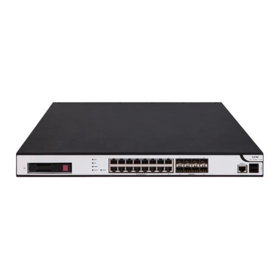
Appendix A Chassis views and technical specifications Chassis views F1005/F1010 The F1005 or F1010 firewall provides the following ports on the front panel: • Eight 10/100/1000BASE-T autosensing Ethernet ports. • Two bypass ports. • Two combo interfaces. • Two USB ports. •... -
Page 52: F1030/F1050/F1060
• Two USB ports. • One console port. • One drive slot. Figure7-3 Front panel (1) Drive slot (2) LEDs (3) 10/100/1000BASE-T copper ports (4) 1000BASE-X fiber ports (5) Console port (6) USB ports (host mode, Type A connector) (7) Management Ethernet port (0/MGMT) Figure7-4 Rear panel (1) Power receptacle (2) Interface module slot 1... - Page 53 (5) Console port (6) USB ports (host mode, Type A connector) (7) Management Ethernet port (0/MGMT) Figure7-6 Rear panel (1) Power receptacle (2) Interface module slot 1 (3) Interface module slot 2 (not supported) (4) Grounding screw F1070/F1080 The F1070 or F1080 firewall provides the following ports on the front panel: •...
- Page 54 F1090 The F1090 firewall provides the following ports on the front panel: • Fourteen 10/100/1000BASE-T autosensing Ethernet copper ports. • Eight 1000BASE-X fiber ports. • Eight 10GBASE-R fiber ports. • Two USB ports. • One console port. • One micro USB port. •...
-
Page 55: F1070/F1080
Table7-1 displays the slots available for interface module installation. Table7-1 Interface module and device slot compatibility Available interface Firewall model Slot number Slot specification modules F1005/F1010 Not supported • NSQM1GT4PFC Slot 1 F1020 Low speed • NSQM1GP4FBA • NSQM1GT4PFC Slots 1 and 2 F1030/F1040/F1050/F1060/ Low speed •... -
Page 56: Ns-Nim-Tg6A
Figure7-12 Front panel of the NSQM1GP4FBA interface module (1) 1000BASE-X fiber ports (2) Captive screw (3) Ejector lever NS-NIM-TG6A The NS-NIM-TG6A interface module provides six 10GBASE-R fiber ports. Figure7-13 Front panel of the NS-NIM-TG6A interface module (1) 10GBASE-R fiber ports (2) Captive screw (3) Ejector lever Drives... -
Page 57: Power Modules
Power modules The F1070/F1080/F1090 firewall comes with power module slot PWR0 installed with a filler panel and power module slot PWR1 empty. It supports both AC and DC power modules. No power modules are provided with the firewall. Prepare power modules for the firewall yourself as required. The F1070/F1080/F1090 firewall supports hot swapping of power modules and 1+1 power module redundancy. -
Page 58: Dc Power Modules
Figure7-15 PSR250-12A1 power module (1) Latch (2) Status LED (3) Handle (4) Power receptacle DC power modules PSR150-D1 The PSR150-D1 power module provides a maximum output power of 150 W. Figure7-16 PSR150-D1 power module (1) Handle (2) Power receptacle PSR450-12D The PSR450-12D power module provides a maximum output power of 450 W. -
Page 59: High-Voltage Dc Power Modules
Figure7-17 PSR450-12D power module (1) Latch (2) Status LED (3) Handle (4) Power receptacle High-voltage DC power modules CAUTION: You can install high-voltage DC power modules only on the F1090 firewall. PSR450-12AHD The PSR450-12AHD power module provides a maximum output power of 450 W. Figure7-18 PSR450-12AHD power module (1) Latch (2) Status LED... -
Page 60: Dimensions And Weights
Dimensions and weights The weight of the firewall includes the chassis and its removable components. Chassis Table7-4 Chassis dimensions and weights Dimensions (H × W × D), excluding rubber Firewall model Weight feet and mounting brackets F1005/F1010 44 × 440 × 230 mm (1.73 × 17.32 × 9.06 in) 3 kg (6.61 lb) F1020 44.2 ×... -
Page 61: Power Consumption
Firewall model Memory F1080 16GB DDR3 F1090 16GB DDR4 Table7-8 Memory specifications of drives Drive model Memory NS-SSD-480G-SATA-SFF 480 GB NS-HDD-500G-SATA-SFF 500 GB NS-HDD-1T-SATA-SFF 1 TB Power consumption The system power consumption includes the power consumptions of the chassis and the removable components. -
Page 62: Power Module Specifications
Power module specifications Table7-12 AC power module specifications Maximum input Maximum Model Rated input voltage range current power PSR150-A1 100 VAC to 240 VAC @ 50 Hz or 60 Hz 150 W PSR250-12A1 100 VAC to 240 VAC @ 50 Hz or 60 Hz 250 W Table7-13 DC power module specifications Maximum input... -
Page 63: Micro Usb Console Port
Micro USB console port Table7-16 Micro USB console port specifications Item Specification Connector Micro USB Standard compliant Micro USB Baud rate 9600 bps (default) to 115200 bps Cable type USB console cable ≤ 10 m (32.81 ft) Transmission distance • Connection to an ASCII terminal •... - Page 64 Table7-19 1000BASE-X SFP transceiver module specifications Central Max transmission Transceiver module Connector Fiber wavelength distance 50/125 µm SFP-GE-SX-MM850-A 850 nm multi-mode optical 0.55 km (1804.46 ft) fiber 9/125 µm SFP-GE-LX-SM1310-A 1310 nm 10 km (6.21 miles) single-mode optical fiber 9/125 µm SFP-GE-LH40-SM1310 1310 nm single-mode optical...
-
Page 65: Appendix B Leds
Central Transceiver module Connector Fiber transmission wavelength distance fiber 220 m (721.78 ft) 50/125 µm multi-mode optical fiber 100 m (328.08 ft) 9/125 µm single-mode SFP-XG-LX-SM1310 1310 nm 10 km (6.21 miles) optical fiber 9/125 µm single-mode SFP-XG-LH40-SM1550 1550 nm 40 km (24.86 miles) optical fiber Appendix B LEDs... -
Page 66: Appendix C Cables
Mark Status Description No link is present. 1000BASE-X fiber port 1000BASE- Steady green A 1000 Mbps link is present. The port is receiving and sending data at Flashing green 1000 Mbps. No link is present. 10GBASE-R fiber port 10GBASE- Steady green A 10 Gbps link is present. -
Page 67: Micro Usb Console Cable
RJ-45 Signal Direction DB-9 → → → Micro USB console cable A micro USB console cable is used to connect the micro USB console port on the firewall to the USB port on a configuration terminal (a PC for example): •... - Page 68 Table9-3 Description for commonly used Ethernet twisted pair cables Type Description Category 5 Suitable for data transmission at a maximum speed of 100 Mbps Category 5e Suitable for data transmission at a maximum speed of 1000 Mbps Category 6 Suitable for data transmission at a speed higher than 1 Gbps Based on whether a metal shielding is used, Ethernet twisted pair cables can be classified into shielded twisted pair (STP) and unshielded twisted pair (UTP).
- Page 69 Figure9-4 Straight-through cable white/orange orange white/green blue white/blue green white/brown brown Straight-through cable white/orange orange white/green blue white/blue green white/brown brown Figure9-5 Crossover cable white/orange orange white/green blue white/blue green white/brown brown Crossover cable white/green green white/orange blue white/blue orange white/brown brown Select an Ethernet twisted pair cable according to the RJ-45 Ethernet port type on your device.
-
Page 70: Making An Ethernet Twisted Pair Cable
10BASE-T/100BASE-TX 1000BASE-T Signal Function Signal Function Sends data BIDA- Bi-directional data cable A- Receives data BIDB+ Bi-directional data cable B+ Reserved BIDC+ Bi-directional data cable C+ Reserved BIDC- Bi-directional data cable C- Receives data BIDB- Bi-directional data cable B- Reserved BIDD+ Bi-directional data cable D+ Reserved... -
Page 71: Optical Fiber
Cut the top of the wires even with one another. Insert the wires into the RJ-45 connector and make sure the wires extend to the front of the RJ-45 connector and make good contact with the metal contacts in the RJ-45 connector and in the correct order. Crimp the RJ-45 connector with the crimping tool until you hear a click. - Page 72 • Before connecting an optical fiber, use dust free paper and absolute alcohol to clean the end face of the two fiber connectors. You can brush the end faces only in one direction. • Never bend or curve a fiber when connecting it. •...
Need help?
Do you have a question about the SecPath F10X0 and is the answer not in the manual?
Questions and answers