H3C SecPath F1070 Manual
Firewall
Hide thumbs
Also See for SecPath F1070:
- Configuration manual (39 pages) ,
- Installation manual (68 pages) ,
- Manual (41 pages)
Table of Contents
Advertisement
Contents
1 Preparing for installation ············································································· 1
Safety recommendations ··································································································································· 1
Safety symbols ··········································································································································· 1
General safety recommendations ·············································································································· 1
Electrical safety ·········································································································································· 2
Laser safety ················································································································································ 2
Handling safety ·········································································································································· 2
Examining the installation site ···························································································································· 3
Weight support ··········································································································································· 3
Temperature and humidity ························································································································· 3
Cleanliness ················································································································································· 3
Cooling system ··········································································································································· 4
ESD prevention ·········································································································································· 4
EMI ····························································································································································· 5
Lightning protection ···································································································································· 5
Power supply ·············································································································································· 5
Installation tools ················································································································································· 6
Accessories ························································································································································ 6
Pre-installation checklist····································································································································· 6
2 Installing the firewall ··················································································· 9
Installation flow··················································································································································· 9
Mounting the firewall on a workbench ················································································································ 9
Installing the firewall in a standard 19-inch rack ······························································································ 10
Rack-mounting the firewall by using front and rear mounting brackets ··················································· 10
Rack-mounting the firewall by using front mounting brackets ·································································· 13
Grounding the firewall ······································································································································ 15
Grounding the firewall with a grounding strip ··························································································· 15
Grounding the firewall with the grounding terminal on the rack ······························································· 16
Installing power modules·································································································································· 16
Installing a power module for an F1070 or F1080 firewall ······································································· 16
Installing a power module for an F1090 firewall ······················································································· 17
Installing an interface module ·························································································································· 18
Installing a drive ··············································································································································· 19
Connecting Ethernet cables ····························································································································· 19
Connecting a copper Ethernet port ·········································································································· 19
Connecting a fiber port ····························································································································· 20
Connecting power cords ·································································································································· 21
Connecting an AC power cord ················································································································· 22
Connecting a DC power cord ··················································································································· 24
Connecting a high-voltage DC power cord for an F1090 firewall ····························································· 24
Verifying the installation ··································································································································· 24
3 Accessing the firewall ············································································ 3-26
Starting the firewall········································································································································ 3-26
Check before starting the firewall ·········································································································· 3-26
Starting the firewall and observing the initial startup conditions···························································· 3-26
Logging in to the firewall ······························································································································· 3-28
Logging in from the Web interface ········································································································ 3-28
Logging in from the serial console port or micro USB console port ······················································ 3-29
Logging in through Telnet ····················································································································· 3-29
4 Hardware replacement··········································································· 4-30
Replacing a power module···························································································································· 4-30
Replacing a power module for an F1070 or F1080 firewall··································································· 4-30
Replacing a power module for an F1090 firewall ·················································································· 4-30
Replacing an interface module ····················································································································· 4-31
i
Advertisement
Table of Contents

Related Manuals for H3C SecPath F1070


Summary of Contents for H3C SecPath F1070
-
Page 1: Table Of Contents
Contents 1 Preparing for installation ············································································· 1 Safety recommendations ··································································································································· 1 Safety symbols ··········································································································································· 1 General safety recommendations ·············································································································· 1 Electrical safety ·········································································································································· 2 Laser safety ················································································································································ 2 Handling safety ·········································································································································· 2 Examining the installation site ···························································································································· 3 Weight support ··········································································································································· 3 Temperature and humidity ·························································································································... - Page 2 Replacing a drive ·········································································································································· 4-32 Replacing a transceiver module ···················································································································· 4-32 5 Hardware management and maintenance ············································· 5-34 Displaying detailed information about the firewall ························································································· 5-34 Displaying the software and hardware version information for the firewall ··················································· 5-34 Displaying the electrical label information for the firewall·············································································· 5-35 Displaying the CPU usage of the firewall ······································································································...
- Page 3 RJ-45 to DB9 console cable ·················································································································· 9-60 Micro USB console cable ······················································································································ 9-60 Ethernet twisted pair cable ···························································································································· 9-61 Introduction ··········································································································································· 9-61 Making an Ethernet twisted pair cable ·································································································· 9-64 Optical fiber ··················································································································································· 9-64...
-
Page 4: Preparing For Installation
Preparing for installation The H3C SecPath F10X0 firewall series include the following models: • F1005 • F1010 • F1020 • F1030 • F1050 • F1060 • F1070 • F1080 • F1090 Safety recommendations To avoid any equipment damage or bodily injury, read the following safety recommendations before installation. -
Page 5: Electrical Safety
Figure1-1 Packing symbols Symbol Description Stored with a maximum stack of n units. Transported and stored with the arrows up. Transported and stored with care. Transported and stored avoiding humidity, rains and wet floor. Electrical safety • Carefully examine your work area for possible hazards such as moist floors, ungrounded power extension cables, and missing safety grounds. -
Page 6: Examining The Installation Site
• Before you move the firewall, remove all cables and mounting brackets. • For long-distance transportation, remove all removable components, such as power modules and interface modules, and package them separately, and install the filler panels supplied with the firewall. For short-distance transportation, make sure all removable components are securely seated in the slots and the screws are fastened. -
Page 7: Cooling System
Substance Concentration limit (particles/m NOTE: Dust particle diameter ≥ 5 µm The equipment room must also meet strict limits on salts, acids, and sulfides to eliminate corrosion and premature aging of components, as shown in Table1-3. Table1-3 Harmful gas limits in an equipment room Max. -
Page 8: Emi
• Maintain the humidity and temperature at an acceptable level. For more information, see "Temperature and humidity." • Put the removed interface modules away on an ESD workbench, with the PCB upward, or put them in ESD bags for future use. •... -
Page 9: Installation Tools
Installation tools All installation tools are user supplied. Flat-head screwdriver Phillips screwdriver Needle-nose pliers Diagonal pliers ESD wrist strap Marker Accessories M6 rack screw and cage nut Mounting bracket Mounting brackets (including M4 (shipped with the F1005 for the F1005 and shoulder screw) for other F10X0 M4 screw and F1010 firewalls and... - Page 10 Item Requirements Result • Operating: Without drives: 0°C to 45°C (32°F to 113°F) Temperature With drives: 5°C to 40°C (41°F to 104°F) • Storage: –40°C to +70°C (–40°F to +158°F) • Operating: Without drives: 5% RH to 95% RH, ...
- Page 11 Item Requirements Result • accessories User-supplied tools • Documents shipped with the firewall Reference • Online documents...
-
Page 12: Installing The Firewall
Keep the tamper-proof seal on a mounting screw on the chassis cover intact, and if you want to open the chassis, contact H3C for permission. Otherwise, H3C shall not be liable for any consequence. The firewall view varies by model. The following figures are for illustration only. This document uses an F1080 firewall as an example. -
Page 13: Installing The Firewall In A Standard 19-Inch Rack
If a standard 19-inch rack is not available, you can place the firewall on a workbench. To mount the firewall on a workbench: Verify that the workbench is sturdy and reliably grounded. Place the firewall upside down on the workbench and clean the four round holes in the chassis bottom with a dry cloth. - Page 14 Wear an ESD wrist strap and make sure the wrist strap makes good skin contact and is reliably grounded. Unpack the firewall and accessories. Mark the cage nut installation positions on the rack posts by using the mounting brackets. Use a front mounting bracket to mark the positions on the front rack posts and use a rear mounting bracket to mark the positions on the rear rack posts.
- Page 15 Distance between the front and rear rack Rear mounting bracket installation posts method door. Figure2-4 Attaching the rear mounting brackets (with the wide flange inside the rack) Figure2-5 Attaching the rear mounting brackets (with the wide flange outside the rack) Mount the firewall in the rack.
-
Page 16: Rack-Mounting The Firewall By Using Front Mounting Brackets
Figure2-6 Mounting the firewall in the rack (with the wide flange of the rear mounting brackets inside the rack) Figure2-7 Mounting the firewall in the rack (with the wide flange of the rear mounting brackets outside the rack) Rack-mounting the firewall by using front mounting brackets The F1005 and F1010 firewalls support this installation method. - Page 17 Figure2-8 Installing cage nuts Attach the front mounting brackets to both sides of the firewall with M4 screws provided with the firewall. Figure2-9 Attaching the front mounting brackets to the firewall Mount the firewall in the rack. Use M6 screws to secure the mounting brackets to the front rack posts.
-
Page 18: Grounding The Firewall
Figure2-10 Mounting the firewall in the rack Grounding the firewall WARNING! • Correctly connecting the firewall grounding cable is crucial to lightning protection and EMI protection. • Do not connect the firewall grounding cable to a fire main or lightning rod. You can ground the firewall in one of the following ways, depending on the grounding conditions available at the installation site. -
Page 19: Grounding The Firewall With The Grounding Terminal On The Rack
Figure2-11 Grounding the firewall with a grounding strip Grounding the firewall with the grounding terminal on the rack Remove the grounding screw from the firewall chassis. Attach the grounding screw to the ring terminal of the grounding cable. Use a Phillips screwdriver to fasten the grounding screw into the grounding hole on the firewall. Remove the grounding screw from the grounding point on the rack. -
Page 20: Installing A Power Module For An F1090 Firewall
Remove the filler panel (if any) from the target power module slot. Figure2-13 Removing the filler panel from an F1070 or F1080 firewall The firewall comes with the PWR1 slot empty and the PWR0 slot installed with a filler panel. Orient the power module with its handle at the left. -
Page 21: Installing An Interface Module
The firewall comes with the PWR1 slot empty and the PWR0 slot installed with a filler panel. Orient the power module with its handle at the right. Holding the handle of the module with one hand and supporting the module bottom with the other, slide the power module slowly into the slot along the guide rails. -
Page 22: Installing A Drive
The device does not come with any drives and cannot recognize drives from other vendors. Purchase drives from H3C as needed. To install a drive: Wear an ESD wrist strap and make sure it makes good skin contact and is reliably grounded. -
Page 23: Connecting A Fiber Port
The firewall supports GE SFP transceiver modules and 10GE SFP+ transceiver modules. For the transceiver module specifications, see "GE fiber Ethernet port" and "10 GE fiber Ethernet port." No transceiver module is provided with the firewall. As a best practice, use H3C transceiver modules. -
Page 24: Connecting Power Cords
Figure2-21 10GE SFP+ transceiver module To connect the firewall to the network through an optical fiber: Remove the dust plug from the fiber port. Remove the dust cap from the transceiver module and insert it into the fiber port. Remove the dust cap of the optical fiber connector, and use dust free paper and absolute alcohol clean the end face of the fiber connector. -
Page 25: Connecting An Ac Power Cord
Connecting an AC power cord Connecting an AC power cord for an F1005 or F1010 firewall Attach the hooks of the power cord retainer clip into the holes on the top of the AC-input power receptacle, and pull the power cord retainer clip upwards. Connect one end of the AC power cord to the AC-input power receptacle on the firewall. - Page 26 Figure2-25 Connecting an AC power cord (using a cable tie to secure the power cord) Connecting an AC power cord for an F1070 or F1080 firewall Connect the connector of the AC power cord to the AC power receptacle on the rear panel of the chassis.
-
Page 27: Connecting A Dc Power Cord
Figure2-28 Connecting an AC power cord for an F1090 firewall Connecting a DC power cord Connecting a DC power cord for an F1070, F1080, or F1090 firewall Correctly orient the DC power cord connector with the power receptacle on the power module, and insert the connector into the receptacle. - Page 28 • There is enough space for heat dissipation around the firewall. • The firewall and its components are installed securely. The screws are fastened tightly. • The power source specifications are as required by the firewall. • The grounding cable and power cords are connected correctly.
-
Page 29: Accessing The Firewall
System is starting... Press Ctrl+D to access BASIC-BOOTWARE MENU... Press Ctrl+T to start heavy memory test Booting Normal Extended BootWare The Extended BootWare is self-decompressing..Done. **************************************************************************** H3C F1080 BootWare, Version 1.04 **************************************************************************** Compiled Date : Sep 10 2014 CPU Type : xxx... - Page 30 BootWare Size : 768KB Flash Size : 8MB CPLD_A Version : 2.0 CPLD_B Version : 2.0 PCB Version : Ver.A BootWare Validating... Press Ctrl+B to access EXTENDED-BOOTWARE MENU... Loading the main image files... Loading file flash:/f1000fw-cmw710-system-E9308.bin.............Done. Loading file flash:/f1000fw-cmw710-boot-E9308.bin..Done.
-
Page 31: Logging In To The Firewall
Known-answer test for DSA(signature/verification) passed. Known-answer test for random number generator passed. Known-Answer tests in the engine passed. Cryptographic Algorithms Known-Answer Tests passed. Line con0 is available. Press ENTER to get started.. Press Enter to access user view of the firewall. NOTE: To access the EXTENDED-BOOTWARE menu, press Ctrl + B within four seconds at the prompt "Press Ctrl+B to access EXTENDED-BOOTWARE MENU."... -
Page 32: Logging In From The Serial Console Port Or Micro Usb Console Port
Logging in from the serial console port or micro USB console port CAUTION: • When you connect the console cable, identify the port marks and make sure you are connecting the correct ports. • The serial ports on PCs do not support hot swapping. To connect a PC to an operating firewall, first connect the PC end. -
Page 33: Hardware Replacement
Hardware replacement CAUTION: Wear an ESD wrist strap or ESD gloves for hardware maintenance. They are not provided with the firewall. Prepare them yourself. Replacing a power module CAUTION: • Before you replace a power module, turn off the circuit breaker and remove the power cord. •... -
Page 34: Replacing An Interface Module
To replace a power module for an F1090 firewall: Face the rear panel of the firewall. Remove the cable tie from the power cord and then remove the power cord connector from the power module. Hold the power module handle with one hand, press the latch towards the handle, and then pull the power module part way out of the slot. -
Page 35: Replacing A Drive
Figure4-3 Removing an interface module Replacing a drive CAUTION: • To avoid storage medium damage, execute the command from the CLI to unmount all umount partitions before removing a drive. • Do not hot swap drives. To replace a drive: Log in to the Web interface. - Page 36 Figure4-5 Transceiver module golden plating Golden plating To replace a transceiver module: Use the command in interface view at the CLI to shut down the optical source shutdown before you remove the fiber connector. Remove the LC connectors with the optical fiber from the transceiver module, and install dust caps to the LC connectors.
-
Page 37: Hardware Management And Maintenance
H3C Comware Software, Version 7.1.064, Release 9313P11 Copyright (c) 2004-2017 New H3C Technologies Co., Ltd. All rights reserved. H3C SecPath F1080 uptime is 0 weeks, 0 days, 2 hours, 23 minutes Last reboot reason: User reboot Boot image: flash:/f1000fw-cmw710-boot- R9313P11.bin Boot image version: 7.1.064, Release 9313P11... -
Page 38: Displaying The Electrical Label Information For The Firewall
DEVICE_SERIAL_NUMBER : 210235A1FXH164000026 MAC_ADDRESS : 487A-DA95-91BB MANUFACTURING_DATE : 2016-04-29 VENDOR_NAME : H3C Fan 0: The operation is not supported on the specified fan. Fan 1: The operation is not supported on the specified fan. Fan 2: The operation is not supported on the specified fan. -
Page 39: Displaying The Memory Usage Of The Firewall
3% in last 5 seconds 3% in last 1 minute 3% in last 5 minutes Table5-2 Output description Field Description Slot 1 CPU 0 CPU usage CPU 0 usage information for the interface module in slot 1. Average CPU usage in the last 5 seconds. (After the firewall boots, the firewall 3% in last 5 seconds calculates and records the average CPU usage at the interval of 5 seconds.) Average CPU usage in the last minute. -
Page 40: Displaying The Operational Status Of Power Modules
Field Description Swap Swap memory. Displaying the operational status of power modules Use the command to display the operational status of power modules. display power <Sysname> display power Power 0 Status: Normal Power 1 Status: Absent Table5-4 Output description Field Description Power Number of the power module. -
Page 41: Displaying The Operational Statistics Of The Firewall
Field Description Warning-UpperLimit Warning-level high temperature alarm threshold. Alarm-UpperLimit Alarm-level high temperature alarm threshold. Shutdown-level high temperature alarm threshold. The firewall automatically Shutdown-Upperlimit powers off when the temperature exceeds this threshold. Displaying the operational statistics of the firewall When you perform routine maintenance or the system fails, you might need to view the operational information of each functional module for locating failures. -
Page 42: Rebooting The Firewall
• Power on the firewall after powering it off, which is also called hard reboot or cold start. H3C does not recommend that you use this method because it might cause data loss and hardware damages. - Page 43 Task Command Remarks and specify a reboot waiting time: scheduler reboot delay 5-40...
-
Page 44: Troubleshooting
Troubleshooting Power module failure Symptom The firewall cannot be powered on, and the power LED (PWR0/PWR1) on the front panel is off. Solution To solve the issue: Power off the firewall. Verify that the power supply is as required by the firewall. Verify that the power cords of the firewall are firmly connected. -
Page 45: Cooling System Failure
If the following alarm information is generated, the temperature of the firewall has reached the warning-level high temperature alarm threshold, %Nov 28 20:02:59:085 2019 H3C DEV/4/TEMPERATURE_WARNING: -Context=1; Temperature is greater than the high-temperature warning threshold on slot 1 sensor outflow 1. Current temperature is 58 degrees centigrade. -
Page 46: Appendix A Chassis Views And Technical Specifications
Appendix A Chassis views and technical specifications Chassis views F1005/F1010 The F1005 or F1010 firewall provides the following ports on the front panel: • Eight 10/100/1000BASE-T autosensing Ethernet ports. • Two bypass ports. • Two combo interfaces. • Two USB ports. •... -
Page 47: F1030/F1050/F1060
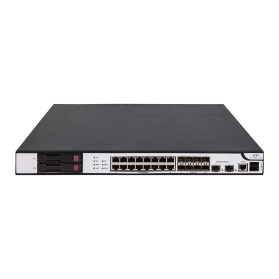
• Two USB ports. • One console port. • One drive slot. Figure7-3 Front panel (1) Drive slot (2) LEDs (3) 10/100/1000BASE-T copper ports (4) 1000BASE-X fiber ports (5) Console port (6) USB ports (host mode, Type A connector) (7) Management Ethernet port (0/MGMT) Figure7-4 Rear panel (1) Power receptacle (2) Interface module slot 1... - Page 48 (5) Console port (6) USB ports (host mode, Type A connector) (7) Management Ethernet port (0/MGMT) Figure7-6 Rear panel (1) Power receptacle (2) Interface module slot 1 (3) Interface module slot 2 (not supported) (4) Grounding screw F1070/F1080 The F1070 or F1080 firewall provides the following ports on the front panel: •...
-
Page 49: F1090
F1090 The F1090 firewall provides the following ports on the front panel: • Fourteen 10/100/1000BASE-T autosensing Ethernet copper ports. • Eight 1000BASE-X fiber ports. • Eight 10GBASE-R fiber ports. • Two USB ports. • One console port. • One micro USB port. •... -
Page 50: Interface Modules
Table7-1 displays the slots available for interface module installation. Table7-1 Interface module and device slot compatibility Available interface Firewall model Slot number Slot specification modules F1005/F1010 Not supported • NSQM1GT4PFC Slot 1 F1020 Low speed • NSQM1GP4FBA • NSQM1GT4PFC Slots 1 and 2 F1030/F1040/F1050/F1060/ Low speed •... -
Page 51: Ns-Nim-Tg6A
Do not hot swap network data encryption modules. The appearance of network data encryption modules varies by models. For more information, see H3C SecPath Firewall Network Data Encryption Module Guide. Table7-2 describes the hardware and software compatibility with the network data encryption modules. -
Page 52: Drives
Network data Applicable Applicable firewalls Applicable slots encryption software version module F1005, F1010 F1020 Slot 1 R9345 and later NSQM1F1KGMB F1030, F1050, F1060, F1070, Slots 1 and 2 R9345 and later F1080 F1090 Slots 1 to 4 R8601P24 and later F1005, F1010 F1020 Slot 1... -
Page 53: Ac Power Modules
Firewall model Available power modules • PSR150-D1 Two power module slots, supporting the following power modules: • PSR250-12A1 F1090 • PSR450-12AHD • PSR450-12D AC power modules PSR150-A1 The PSR150-A1 power module with a product code of PSR150-A1-B provides a maximum output power of 150 W. -
Page 54: Dc Power Modules
Figure7-15 PSR250-12A1 power module (1) Latch (2) Status LED (3) Handle (4) Power receptacle DC power modules PSR150-D1 The PSR150-D1 power module with a product code of PSR150-D1-B provides a maximum output power of 150 W. Figure7-16 PSR150-D1 power module (1) Handle (2) Power receptacle PSR450-12D... -
Page 55: High-Voltage Dc Power Modules
Figure7-17 PSR450-12D power module (1) Latch (2) Status LED (3) Handle (4) Power receptacle High-voltage DC power modules CAUTION: You can install high-voltage DC power modules only on the F1090 firewall. PSR450-12AHD The PSR450-12AHD power module with a product code of PSR450-12AHD provides a maximum output power of 450 W. -
Page 56: Dimensions And Weights
Dimensions and weights The weight of the firewall includes the chassis and its removable components. Chassis Table7-5 Chassis dimensions and weights Dimensions (H × W × D), excluding rubber Firewall model Weight feet and mounting brackets F1005/F1010 44 × 440 × 230 mm (1.73 × 17.32 × 9.06 in) 3 kg (6.61 lb) F1020 44.2 ×... -
Page 57: Storage Media
Storage media Table7-9 Storage media specifications of the device Firewall model Memory F1005/F1010 2GB DDR3 F1020 2GB DDR3 F1030/F1050 4GB DDR3 F1060/F1070 8GB DDR3 F1080 16GB DDR3 F1090 16GB DDR4 Table7-10 Memory specifications of drives Drive model Memory NS-SSD-480G-SATA-SFF 480 GB NS-HDD-500G-SATA-SFF 500 GB NS-HDD-1T-SATA-SFF... -
Page 58: Network Data Encryption Modules
Network data encryption modules Table7-13 Network data encryption module power consumption Network data encryption module model Power consumption NSQM1F1KGM0 4.14 W NSQM1F1KGMB 3.7 W NSQM1F1KGMC 5.7 W Drives Table7-14 Drive power consumption Drive model Power consumption NS-SSD-480G-SATA-SFF NS-HDD-500G-SATA-SFF 4.9 W NS-HDD-1T-SATA-SFF Power module specifications Table7-15 AC power module specifications... -
Page 59: Port Specifications
Port specifications Console port Table7-18 Console port specifications Item Specification Connector RJ-45 Standard compliant RS-232 Baud rate 9600 bps (default) to 115200 bps Cable type Common asynchronous serial port cable ≤ 15 m (49.21 ft) Transmission distance • Connection to an ASCII terminal •... -
Page 60: 10 Ge Fiber Port
Item Specification 100 Mbps, half/full-duplex 1000 Mbps, full-duplex NOTE: The media dependent interface (MDI) standard is typically used on the Ethernet port of network adapters. The media dependent interface crossover (MDI-X) standard is typically used on hubs or LAN switches. GE fiber port Table7-21 GE fiber port specifications Item... -
Page 61: Appendix B Leds
Table7-23 10 GE fiber port specifications Item Specification Connector type Transceiver module type SFP+ Standard compliance 10GBASE-R Interface speed LAN PHY: 10.3125 Gbps/1000 Mbps Table7-24 10 Gbps SFP+ transceiver module specifications Central Transceiver module Connector Fiber transmission wavelength distance 300 m (984.25 ft) 50/125 µm multi-mode 82 m (269.03 ft) optical fiber... - Page 62 Figure8-1 LEDs (1) System status LED (2) Drive status LED (3) 10/100/1000BASE-T copper port LED (4) 1000BASE-X fiber port LED (5) 10GBASE-R fiber port LED (6) Interface module LED (7) Power module LED Table8-2 LED description Mark Status Description The firewall is not powered on or has failed. System status LED Slow flashing green The firewall is operating correctly.
-
Page 63: Appendix C Cables
Appendix C Cables Console cable RJ-45 to DB9 console cable An RJ-45 to DB9 console cable is used to connect the console port on the firewall to the serial port on a configuration terminal (a PC for example): • Connect the DB9 female connector of the cable to the 8-core serial port on the configuration terminal. -
Page 64: Ethernet Twisted Pair Cable
Figure9-2 Micro USB console cable Type A connector Type B connector Table9-2 Micro USB console cable pinouts USB Type A USB Type mini-A/B Signal Signal connector connector VBUS VBUS ID(NC) Ethernet twisted pair cable Introduction An Ethernet twisted pair cable consists of four pairs of insulated copper wires twisted together. Every wire uses a different color, and has a diameter of about 1 mm (0.04 in). - Page 65 Figure9-3 RJ-45 connector pinout PIN #8 PIN #1 NOTE: The RJ-45 Ethernet ports of the firewall use category 5 or higher Ethernet twisted pair cables for connection. EIA/TIA cabling specifications define two standards, 568A and 568B, for cable pinouts. • Standard 568A—pin 1: white/green stripe, pin 2: green solid, pin 3: white/orange stripe, pin 4: blue solid, pin 5: white/blue stripe, pin 6: orange solid, pin 7: white/brown stripe, pin 8: brown solid.
- Page 66 Figure9-5 Crossover cable white/orange orange white/green blue white/blue green white/brown brown Crossover cable white/green green white/orange blue white/blue orange white/brown brown Select an Ethernet twisted pair cable according to the RJ-45 Ethernet port type on your device. An RJ-45 Ethernet port can be MDI (for routers and PCs) or MDIX (for switches). Table9-4 Table9-5 show their pinouts.
-
Page 67: Making An Ethernet Twisted Pair Cable
10BASE-T/100BASE-TX 1000BASE-T Signal Function Signal Function Sends data BIDA- Bi-directional data cable A- Reserved BIDC+ Bi-directional data cable C+ Reserved BIDC- Bi-directional data cable C- To ensure normal communication, the pins for sending data on one port must correspond to the pins for receiving data on the peer port. - Page 68 Item Single mode fiber Multi-mode fiber transmission distance within campus backbones for distance LANs or distances of a couple hundred of several thousand meters meters within a campus network Table9-7 Allowed maximum tensile force and crush load Period of force Tensile load (N) Crush load (N/mm) Short period...
Need help?
Do you have a question about the SecPath F1070 and is the answer not in the manual?
Questions and answers