
Subscribe to Our Youtube Channel
Related Manuals for H3C SecPath F100-C-A-W


Summary of Contents for H3C SecPath F100-C-A-W
- Page 1 H3C SecPath F100-C-A-W Firewalls Installation Guide New H3C Technologies Co., Ltd. http://www.h3c.com Document version: 6W101-20200713...
- Page 2 The information in this document is subject to change without notice. All contents in this document, including statements, information, and recommendations, are believed to be accurate, but they are presented without warranty of any kind, express or implied. H3C shall not be liable for technical or editorial errors or omissions contained herein.
- Page 3 Preface The installation guide describes preparing for installation, installing the firewall, logging in to the firewall, hardware management and maintenance, and troubleshooting. This preface includes the following topics about the documentation: • Audience. • Conventions. • Documentation feedback. Audience This documentation is intended for: •...
- Page 4 Symbols Convention Description An alert that calls attention to important information that if not understood or followed WARNING! can result in personal injury. An alert that calls attention to important information that if not understood or followed CAUTION: can result in data loss, data corruption, or damage to hardware or software. An alert that calls attention to essential information.
- Page 5 Documentation feedback You can e-mail your comments about product documentation to info@h3c.com. We appreciate your comments.
-
Page 6: Table Of Contents
Contents Preparing for installation ················································································ 1 Safety recommendations ··································································································································· 1 Safety symbols ··········································································································································· 1 General safety recommendations ·············································································································· 1 Electrical safety ·········································································································································· 2 Handling safety ·········································································································································· 2 Examining the installation site ···························································································································· 2 Weight support ··········································································································································· 2 Temperature and humidity ························································································································· 3 Cleanliness ·················································································································································... - Page 7 Troubleshooting ··························································································· 26 Power failure ···················································································································································· 26 Configuration terminal display issue ················································································································ 26 Password loss ·················································································································································· 26 Software loading failure···································································································································· 27 Appendix A Chassis views and technical specifications ······························· 28 Chassis views ·················································································································································· 28 F100-C-A3-W/F100-C-A5-W ···················································································································· 28 F100-C-A6-WL ········································································································································· 29 Technical specifications ···································································································································...
-
Page 8: Preparing For Installation
Preparing for installation The H3C SecPath F100-C-A-W firewall series include the following models: • F100-C-A3-W • F100-C-A5-W • F100-C-A6-WL Safety recommendations To avoid any equipment damage or bodily injury, read the following safety recommendations before installation. Note that the recommendations do not cover every possible hazardous condition. -
Page 9: Electrical Safety
Symbol Description Keep the device from humidity, rains, and wet floor. • When stacking devices, place the heavier and larger ones at the bottom. Make sure the devices are stacked evenly. • Ensure good ventilation of the equipment room and keep the air inlet and outlet vents of the firewall free of obstruction. -
Page 10: Temperature And Humidity
Temperature and humidity Maintain appropriate temperature and humidity in the equipment room. • Lasting high relative humidity can cause poor insulation, electricity leakage, mechanical property change of materials, and metal corrosion. • Lasting low relative humidity can cause washer contraction and ESD and bring problems including loose captive screws and circuit failure. -
Page 11: Esd Prevention
ESD prevention ESD prevention guidelines To prevent electrostatic discharge (ESD), follow these guidelines: • Make sure the firewall, the workbench, and the rack are reliably grounded. • Take dust-proof measures for the equipment room. For more information, see "Cleanliness." • Maintain the humidity and temperature at an acceptable level. -
Page 12: Lightning Protection
To prevent EMI, use the following guidelines: • If AC power is used, use a single-phase three-wire power receptacle with protection earth (PE) to filter interference from the power grid. • Keep the firewall far away from radio transmitting stations, radar stations, and high-frequency devices. -
Page 13: Installation Accessories
Installation accessories Table1-5 Installation accessories M4 mounting bracket M6 rack screw (user Mounting bracket Rubber feet screw supplied) Screw anchor and Cage nut (user supplied) Grounding cable Power cord retainer clip screw F100-C-A6-WL 4G Console cable Power cord Wi-Fi antenna antenna Pre-installation checklist Table1-6 Pre-installation checklist... - Page 14 Item Requirements Result • Keep the firewall far away from radio stations, radar and high-frequency devices working in high current. • Use electromagnetic shielding when necessary. • The grounding cable of the chassis is reliably grounded. Lightning • The grounding terminal of the AC power receptacle is protection reliably grounded.
-
Page 15: Installing The Firewall
Keep the tamper-proof seal on a mounting screw on the chassis cover intact, and if you want to open the chassis, contact H3C for permission. Otherwise, H3C shall not be liable for any consequence. The installation procedure is the same for the H3C SecPath F100-C-A-W series firewalls. This document uses the F100-C-A6-WL firewall as an example. -
Page 16: Mounting The Firewall On A Workbench
Mounting the firewall on a workbench IMPORTANT: • Ensure good ventilation and a minimum clearance of 100 mm (3.94 in) around the chassis for heat dissipation. • Avoid placing heavy objects on the firewall. If a standard 19-inch rack is not available, you can place the firewall on a workbench. To mount the firewall on a workbench: Verify that the workbench is sturdy and reliably grounded. - Page 17 Install cage nuts. Figure1-5 Installing cage nuts Use the provided M4 mounting bracket screws to secure the mounting brackets to both sides of the firewall. Figure1-6 Securing mounting brackets to the firewall Mount the firewall in the rack. Use M6 rack screws to secure the mounting brackets to the front rack posts.
-
Page 18: Mount The Firewall On A Wall
Figure1-7 Mounting the firewall in the rack Mount the firewall on a wall Unpack the firewall and accessories. Mark two installation holes spaced 102 mm (4.02 in) apart on the wall. Drill holes with a diameter of 6 mm (0.24 in) and a depth of 22 mm (0.87 in) at the marked locations. -
Page 19: Grounding The Firewall
Figure1-8 Mounting the firewall on a wall Grounding the firewall WARNING! • Correctly connecting the firewall grounding cable is crucial to lightning protection and EMI protection. • Do not connect the firewall grounding cable to a fire main or lightning rod. If you mount the firewall on a wall, connect the firewall to the grounding facility of the building. -
Page 20: Grounding The Firewall With The Grounding Terminal On The Rack
Figure1-9 Grounding the firewall with a grounding strip Grounding the firewall with the grounding terminal on the rack Remove the grounding screw from the firewall chassis. Attach the grounding screw to the ring terminal of the grounding cable. Use a Phillips screwdriver to fasten the grounding screw into the grounding hole on the firewall. Remove the grounding screw from the grounding point on the rack. -
Page 21: Installing Optional Components
Installing optional components (Optional) Installing a SIM card CAUTION: • Before installing or removing a SIM card, make sure the firewall is powered off. • Do not touch the components on the SIM card. • To avoid damaging the SIM card slot, do not use excessive force when installing a SIM card. Only the F100-C-A6-WL supports SIM cards. -
Page 22: (Optional) Installing A Lightning Arrester For An Ac Power Module
(Optional) Installing a lightning arrester for an AC power module No lightning arrester is provided with the firewall. Purchase one as needed. If part of the AC power cord is routed outdoors, install a lightning arrester to the power input end to protect the firewall from being damaged by lightning strikes. -
Page 23: Connecting Ethernet Cables
4G antenna in a location where the 4G signal is strong. No extension cable is provided with the firewall. Purchase one as required. To avoid extension cable incompatibility with the firewall, contact the H3C sales personnel or sales agents for compatible extension cables. -
Page 24: Connecting An Ac Power Cord
Connecting an AC power cord CAUTION: Make sure the grounding cable of the firewall is correctly connected and the power source is powered off before connecting the power cord. To connect an AC power cord: Attach the hooks of the power cord retainer clip into the holes on the top of the AC-input power receptacle, and pull the power cord retainer clip upwards. -
Page 25: Accessing The Firewall
Accessing the firewall By default, the firewall uses the scheme access authentication mode. The username and password are both admin. Setting up the configuration environment and configuring terminal parameters You can connect the console port on the firewall to a configuration terminal (a PC for example) for accessing the firewall for the first time. -
Page 26: Logging In To The Firewall
Press Ctrl+T to start heavy memory test. Booting Normal Extended BootWare The Extended BootWare is self-decompressing...Done. **************************************************************************** H3C SecPath BootWare, Version 1.03 **************************************************************************** Copyright (c) 2004-2018 New H3C Technologies Co., Ltd. Compiled Date : Aug 10 2018 Memory Type : DDR3 SDRAM Memory Size... -
Page 27: Logging In From The Web Interface
• Logging in from the Web interface • Logging in from the console port • Logging in through Telnet Logging in from the Web interface IMPORTANT: After accessing the Web interface with the default account, modify the password of the default account or create a new administrator account and delete the default account as a best practice. -
Page 28: Hardware Management And Maintenance
H3C Comware Software, Version 7.1.064, Alpha 9601P03 Copyright (c) 2004-2018 New H3C Technologies Co., Ltd. All rights reserved. H3C SecPath F100-C-A6-WL uptime is 1 week, 4 days, 2 hours, 47 minutes Boot image: flash:/f1010fww-cmw710-boot-a9601p03.bin Boot image version: 7.1.064, Alpha 9601P03 Compiled Nov 07 2018 16:00:00 System image: flash:/f1010fww-cmw710-system-a9601p03.bin... -
Page 29: Displaying The Electrical Label Information Of The Firewall
Slot 1 CPU 0: DEVICE_NAME : SecPath F100-C-A6-WL DEVICE_SERIAL_NUMBER : 219801A1TAH16C000002 MAC_ADDRESS : D461-FE39-D20C MANUFACTURING_DATE : 2017-01-13 VENDOR_NAME : H3C Power 0: The operation is not supported on the specified power. Table1-7 Output description Field Description DEVICE_NAME Firewall name. DEVICE_SERIAL_NUMBER Firewall serial number. -
Page 30: Displaying The Memory Usage Of The Firewall
Field Description Average CPU usage in the last 5 minutes. (After the firewall boots, the firewall 3% in last 5 minutes calculates and records the average CPU usage at the interval of 5 minutes.) Displaying the memory usage of the firewall Use the command to display the memory information of the firewall. -
Page 31: Displaying The Operational Statistics Of The Firewall
Table1-10 Output description Field Description Power Number of the power module. Power module state: • Normal—The power module is operating correctly. Status • Absent—The power module is not present. • Abnormal—The power module is faulty. Displaying the operational statistics of the firewall When you perform routine maintenance or the system fails, you might need to view the operational information of each functional module for locating failures. -
Page 32: Rebooting The Firewall
• Power on the firewall after powering it off, which is also called hard reboot or cold start. H3C does not recommend that you use this method because it might cause data loss and hardware damages. -
Page 33: Troubleshooting
Troubleshooting Power failure Symptom The firewall cannot be powered on, and the power status LED (PWR) on the front panel is off. Solution To resolve the issue: Turn off the circuit breaker for power input to the firewall. Verify that the power source is as required by the firewall. Verify that the power cord is firmly connected. -
Page 34: Software Loading Failure
Software loading failure Symptom The device fails in software loading. Solution To resolve the issue: Verify that the physical ports are correctly connected. Examine the software loading process displayed on the TeraTermPro or PuTTY for errors. Possible errors include: Inconsistent baud rates configured for XMODEM and the TeraTermPro or PuTTY. ... -
Page 35: Appendix A Chassis Views And Technical Specifications
Appendix A Chassis views and technical specifications Chassis views F100-C-A3-W/F100-C-A5-W Front panel The F100-C-A3-W/F100-C-A5-W firewall provides the following ports on the front panel: • Eight 10/100/1000BASE-T autosensing Ethernet copper ports. • One USB port. • One console port. Figure1-16 Front panel (1) Reset button (2) USB port (3) Console port... -
Page 36: F100-C-A6-Wl
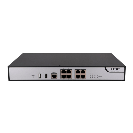
F100-C-A6-WL Front panel The F100-C-A6-WL firewall provides the following ports on the front panel: • Eight 10/100/1000BASE-T autosensing Ethernet copper ports. • One USB port. • One console port. Figure1-18 Front panel (1) Reset button (2) USB port (3) Console port (4) 10/100/1000BASE-T copper ports (5) LEDs (6) Management Ethernet port GE1/0/0... -
Page 37: Technical Specifications
Technical specifications Dimensions and weights Table1-11 Dimensions and weights Item Specification Dimensions (H × W × D), excluding rubber feet and 43.6 × 330 × 230 mm (1.72 × 12.99 × 9.06 in) mounting brackets Weight 2.2 kg (4.85 lb) Storage media Table1-12 Storage media specifications Item... - Page 38 Item Description USB port 1 (host mode, type A connector) Fixed Ethernet port 8 × GE copper ports Expansion slot Not supported • F100-C-A3-W/F100-C-A5-W: Not supported SIM card slot • F100-C-A6-WL: 1 (standard SIM card) • F100-C-A3-W/F100-C-A5-W: Not supported 4G antenna connector •...
- Page 39 WLAN module ports The WLAN module (model: SIC-AP320) is a WLAN access module that sends and receives wireless packets. It has two Wi-Fi antenna connectors and is compliant with 802.11a/b/g/n/ac. It supports 2.4 GHz and 5 GHz bands. Table1-18 WLAN module ports Item Specification Connector...
-
Page 40: Appendix B Leds
Appendix B LEDs Table1-19 LED description for the F100-C-A3-W/F100-C-A5-W firewall Mark Status Description The firewall is not powered on or has failed. System status LED Slow flashing green The firewall is operating correctly. Fast flashing green The firewall is loading software. The power system is faulty. - Page 41 Mark Status Description Alternating between Both the 2.4 GHz and 5 GHz radios yellow and amber have client access.
-
Page 42: Appendix C Cables
Appendix C Cables Console cable A console cable is an 8-core shielded cable with an RJ-45 connector at one end and a DB9 female connector at the other end. It is used to connect the console port on the firewall to a serial port on a configuration terminal (for example, a PC): •... - Page 43 Ethernet twisted pair cables can be classified into category 3, category 4, category 5, category 5e, category 6, and category 7 cables based on performance. In LANs, category 5, category 5e, and category 6 are commonly used. Table1-23 Description for commonly used Ethernet twisted pair cables •...
- Page 44 Figure1-22 Straight-through cable white/orange orange white/green blue white/blue green white/brown brown Straight-through cable white/orange orange white/green blue white/blue green white/brown brown Figure1-23 Crossover cable white/orange orange white/green blue white/blue green white/brown brown Crossover cable white/green green white/orange blue white/blue orange white/brown brown Select an Ethernet twisted pair cable according to the RJ-45 Ethernet port type on your device.
-
Page 45: Making An Ethernet Twisted Pair Cable
• 10BASE-T/100BASE-TX • 1000BASE-T • Pin • Signal • Function • Signal • Function • • • • • Sends data BIDA- Bi-directional data cable A- • • • • • Receives data BIDB+ Bi-directional data cable B+ • • •... - Page 46 Untwist the pairs so that they can lay flat, and arrange the colored wires based on the wiring specifications. Cut the top of the wires even with one another. Insert the wires into the RJ-45 connector and make sure the wires extend to the front of the RJ-45 connector and make good contact with the metal contacts in the RJ-45 connector and in the correct order.
Need help?
Do you have a question about the SecPath F100-C-A-W and is the answer not in the manual?
Questions and answers