
Subscribe to Our Youtube Channel
Related Manuals for Nakanishi E2280


Summary of Contents for Nakanishi E2280
- Page 1 E2280 CONTROLLER 取扱説明書 / OPERATION MANUAL 日本語 : P1- P55/ English : P57- P114/ French : P117- P121 OM-K0681...
-
Page 2: Table Of Contents
Always use an Air Line Kit to ensure clean, dry, properly regulated air is supplied to the motor and spindle. The E2280 system is capable of being used with coolants and cutting lubricants. -
Page 3: Important Instructions And Warning - Electric Devices
2. Replace cracked collet or collet nut immediately. 3. Do not over tighten the collet nut. 4. Use only NAKANISHI manufactured collets and arbors for grinding and sawing applications. 5. REMOVE ADJUSTING KEYS AND WRENCHES. Always check to see that keys and adjusting wrenches are removed from tool before turning the units Main Power Switch on. -
Page 4: Cautions For Handling And Operation
DANGER ① NAKANISHI warns all end-users not to remove the Power Cord or Motor Cord while the Control Power is ON. Not following these instructions may lead to serious injury or death due to electric shock. - Page 5 ⑤ Do not disassemble, modify or attempt to repair the CONTROLLER or motor spindle. Additional damage will occur to the internal components. Service must be performed by NSK NAKANISHI or an authorized service center.
- Page 6 ㊱ Disconnect CONTROLLER from power before doing maintenance on replacing tools or fuses as specified. ㊲ Do not use in flammable or explosive atmospheres. ㊳ Send back to NSK NAKANISHI or an authorized service center for servicing / repair. ㊴ Use the CONTROLLER in pollution degree 2 environment.
-
Page 7: Basic Package
When opening the package, check if it includes all items listed in " Table. 1 Packing List Contents ". In the event of any shortage, please contact either NAKANISHI (see the " 4. CONTACT US " section) or your local dealer. -
Page 8: Warranty
⑧ By setting the parameter , Emergency Operating Function can be utilized. Using the open detection signal of the motor power line and the disconnect of the motor power line by safety relay, allows the E2280 CONTROLLER to establish a safe spindle system. -
Page 9: Specifications And Dimensions
500 - 1,060hPa Pressure Height above Sea Level Less than 2000m 6 - 2 Compatibility (1) The E2280 CONTROLLER is compatible with the following overseas safety standard. ・Safety standard in North America (UL,CSA) UL 61010-1 CSA 61010-1 ・EC Directive Low Voltage Directive IEC / EN 61010-1 EMC Directive... -
Page 10: System Chart
(rpm) 30,000min (rpm) 1,000 - 50,000min Compressor Reducer ARG-2516N (1/16 Reduction) Brushless Motor EM25N-5000-J4 Air Line Kit E2280 50,000min (rpm) (Cord with Quick Disconnect) AL - C1204 CONTROLLER *Cooled - air is supplied. Lever Type Spindle (100V - 240V) NRR-2651... -
Page 11: Torque Characteristics
2,870min (rpm) (Cord with Quick Disconnect) Compressor Angle Type Spindle 1,000 - 50,000min (rpm) RA-100 (1/2.67 Reduction) E2280 Air Line Kit CONTROLLER AL - C1204 2,870min (rpm) (100V - 240V) *Cooled - air is supplied. Brushless Motor Angle Type Spindle... -
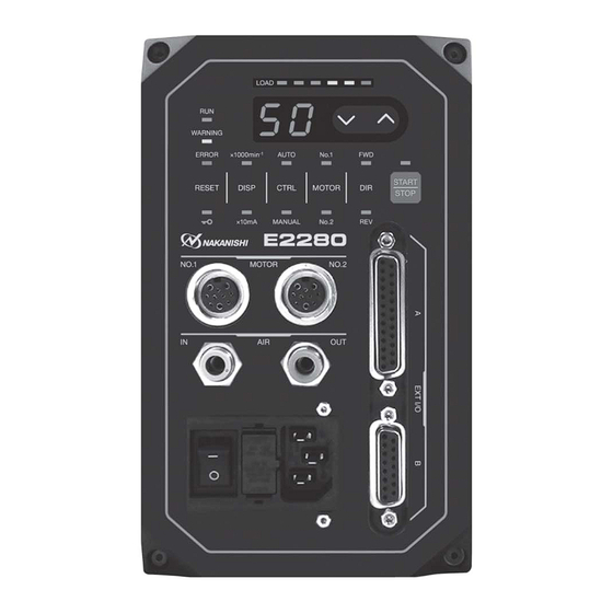
Page 12: Control Panel Features
AIR HOSE CONNECTION " section. CAUTION If the air pressure is too low the E2280 CONTROLLER will not operate. ⑧ Air Output Joint Connect Air Hose to supply clean, dry, regulated air for motor spindle cooling and purging. Refer to P71 " 14. AIR HOSE CONNECTION "... -
Page 13: Power Cord Connection
⑩ Main Power Inlet with Power Supply Fuses Insert the supplied power cord connector. Refer to P68 " 10. POWER CORD CONNECTION " section. Two fuses (T1.6AL (250V)) have been installed. Make sure the properly rated and type of fuses are used when replacements are necessary. - Page 14 10 - 1 Wiring of the power cord CAUTION ・ Be sure to connect the ground wire to the earth ground. Insufficient grounding could cause an electric shock or fire, and malfunction. ・ When connecting the power cord to the AC Power Input Terminal Block, tighten the screw securely. Loose Terminal Screws to the AC Power Input Terminal Block will cause overheating leading to damage and fire in the CONTROLLER.
-
Page 15: Replacing Fuses
11. REPLACING FUSES WARNING ・ Before removing the fuse holder and fuses, be sure that the Main Power Switch ⑨ is turned OFF and the Power Cord Connector has been removed from the CONTROLLER. ・ Verify type and use only following the properly rated and type of fuse. ... -
Page 16: Motor Cord Connection
Fig. 16 14 . AIR HOSE CONNECTION CAUTION When not using NAKANISHI Air Line Kit, make sure that the incoming air supply is dry, clean and properly regulated. 14 - 1 One Motor Spindle is connected to the CONTROLLER (Fig. 17) ⑦... - Page 17 14 - 2 Two Motor Spindles are connected to the CONTROLLER (Fig. 18) ⑦ ⑧ (1) Insert the provided 6mm Air Hose with Filter Air Branching Joint from the Air Line Kit AL-C1204 into the Air Input Joint ⑦ on the front of the CONTROLLER. (2) Insert the Air Branching Joint (standard accessories) to the Air Output Joint ⑧...
-
Page 18: Operation Procedures
15. OPERATION PROCEDURES 15 - 1 Button and LED Features of the Control Panel ⑬ ⑭ ⑮ ㉔ ㉓ ㉒ ㉑ ㉕ ⑳ ⑲ ⑱ ⑰ ⑯ Fig. 19 This Operation Manual indicates the LED status as shown below. :LED lights :LED brinks Table. - Page 19 Button / LED Description Start / Stop Button START / STOP LED The motor spindle is not rotating. (START / STOP) ⑯ goes out (not lit) START / STOP LED lights The motor spindle is rotating at the specified speed. Rotation Direction Button Select the right (FWD.) or left (REV.) rotation direction for the motor spindle.
- Page 20 Button / LED Description Control Button Switch the control mode to MANUAL or AUTO. (CTRL) ⑲ MANUAL LED Controlled by Control Panel ② . (MANUAL) lights AUTO LED Controlled by input signal to Input / Output Connector A ③ from External Signal Source. (AUTO) lights DISPLAY (DISP) Button ⑳...
- Page 21 Button / LED Description Error Reset Button (RESET) This switch resets and allows restarting of the motor spindle after an error has ㉑ been corrected. To reset when an error occurs, 1. Remove or correct the cause of the error. Check P94 "...
- Page 22 Button / LED Description A Key Hold Function is equipped to prevent erroneous operation by touching the KEY HOLD LED ( Button ㉕ control panel. All button operations will be disabled. All button operations are enabled. KEY HOLD LED ( goes out (not lit) To disable button operations on the Control Panel ②...
- Page 23 (4) Setting Motor Speed ) ⑮ of the Fig. 20.) Setting Motor Speed (Set the Motor Speed Adjustment Button (SPEED ) ⑮ . Set the speed by pushing the Motor Speed Adjustment Button (SPEED ・Motor Speed Range is 1,000 - 50,000min (rpm).
- Page 24 ③ Set by the Speed Point Signal (Set parameter . (Refer to P106 " 18 - 4 ⑦ Selection of External Speed Control Mode " section.)) Select the 4 Speed Points set beforehand by combination of " Speed Point Select 0 (POINT 0) (Pin No. 17 : SEL0) "...
-
Page 25: External Input / Output Connector
16. EXTERNAL INPUT / OUTPUT CONNECTOR 16 - 1 External Input / Output Connector A ③ (1) Details of External Input / Output Connector A ③ Signals WARNING ・ DO NOT connect any circuit other than SELV (DC+ 24 V) (Safety Extra Low Voltage) to the External Input / Output Connector A ③... - Page 26 Code Function Input / Description Output SEL1 Count Pulse Input ― One pulse will increase or decrease 1,000min Signal for in Spindle Speed depending on parameter setting. (Refer to P106 " 18 - 4 ⑦ Setting Motor Speed Selection of External Speed Control Mode " (CNT_IN) section.) Speed Point Signal can be selected.
- Page 27 Code Function Input / Description Output START Rotate Input ' OFF (Open) ' : Stop Motor Start and Motor Stop Signal Command ' ON (Closed) ' : Start Setting parameter , can start with forward rotation. (Refer to P107 " 18 - 4 ⑧ Selection of External Motor Start Signal Control Mode "...
- Page 28 Code Function Input / Description Output Motor No. 1 Input Set rotating speed Sets rotating speed of the motor. When using 30,000min of motor speed, setting parameter Speed (x 10,000min (Refer to P108 " 18 - 4 ⑩ Control Selection x (9VR-1) Voltage of Motor Speed Control Voltage / DC+10V...
- Page 29 (2) Input / Output Diagram COM_1 (+24V or 0V) START DIR_OUT DIR_IN RESET SEL_MT 500min WARNING Connector A SEL0 (D-Sub25) COIN SEL1 MT_SEL PULSE COM_2 (OV or +24V) +10V DC MOTOR_1 Variable Registor LOAD Variable Registor SPEED_V MT-CNA MT-CNB AUTO+ Connector B EMG-IN+ AUTO–...
- Page 30 (3) Input / Output Signal ① Input Signal There are 7 different input signals : " Rotate Command (START) ", " Rotating Direction Setting (DIR_IN) ", " Rotates Motor at " Centering " speed (500min (rpm)) ", " Error Release (RESET) ", " Speed Point Select 0 (POINT 0) ", "...
- Page 31 ③ Output Signal Ⅱ Refer to Fig. 24 regarding the Output Signal of the " Rotating Pulse (PULSE) ". The output signal can be connected for either sinking or sourcing. Voltage and Current Specifications ・Applied Voltage (V) ≦ DC+30V ・Working Current (lp) ≦ 50mA DC+24V or DC0V The side of CONTROLLER (COM_2)
- Page 32 Torque Characteristics.( parameter is 50,000min (rpm) 30,000min (rpm) 0.28 VR1 / VR2 ( DCV) * VR = VR1or VR2 * Less than 0.3V : 1,000min (rpm) * Unit of rotational speed : 1,000min (rpm) * Rotation Speed(x10,000min (rpm))=1 / 16 x (9VR-1) or VR(V) (16 x Rotation Speed(x10,000min (rpm))+1) / 9 ex) The VR (V) at the 50,000min...
- Page 33 16 - 2 External Input / Output Connector B ④ (1) Details of External Input / Output Connector B ④ Signals WARNING ・ DO NOT connect any circuit other than SELV ( DC+ 24 V) (Safety Extra Low Voltage) to the External Input / Output Connector B ④...
- Page 34 Code Function Input / Description Output Not Used ― ― ― *Note : Never use pin labeled not used. Not Used ― ― ― *Note : Never use pin labeled not used. EMG-INB Emergency Stop Input External Power External Power Source input for Emergency Source input for Stop Signal or Emergency Stop Signal.
- Page 35 (2) Input / Output Signals ① Output Signal Pin No. 2 - 10, 5 - 13, 6 - 14 There are 3 different output signals : " Motor Connect Contact (MT-CN) ", " Control Mode AUTO Signal (AUTO) ", and " CONTROLLER Power Source Monitor (PWON) ". These signals are MOSS Relay Contact Connections.
- Page 36 ③ Safety Relay Signal CAUTION If the Emergency Stop Function is not installed, the Emergency Stop Signal (EMG - IN) will not function. (Refer to P108 " 18 - 4 ⑪ If enabling the Emergency Stop Function, it is necessary to set parameter Selection of Emergency Stop Function "...
- Page 37 16 - 3 External Input / Output Connector Specifications CAUTION ・ To minimize RF interference and noise, please keep the length of the cables as short as possible and route them separately or as far away as possible from high voltage electrical cables. ・...
-
Page 38: Protect Function
17. PROTECT FUNCTION 17 - 1 WARNING FUNCTION CAUTION When the Warning LED (WARNING) ㉓ on the CONTROLLER blinks, conditions exist that could result in dangerous operation. Check operating conditions and continue to use only after correcting the problem. Always check the CONTROLLER, motor spindle and the condition of the cooling air prior to use. This will help prevent system errors that will result in non - operational conditions. - Page 39 * Setting parameter , will Change the Error Output Mode of the Error Signal. (Refer to P104 " 18 - 4 ① Setting of Error Output Mode " section.) ". (Refer to P110 " 18 - 4 ⑭ * Error history can be checked with parameter " Error History ".) 17 - 3 Resetting System after Error Codes There are 2 methods of releasing Error Code.
- Page 40 If you constantly operate the system in an overload condition, even for short periods of time, the CONTROLLER will overheat and damage to the CONTROLLER and motor spindle are possible. NAKANISHI recommends only continuous duty operation (LOAD LEDs with 3 LEDs lit) : Torque Load Monitor (LOAD) Voltage should be less than 5V.
-
Page 41: Setting Of Operating Parameters
18. SETTING OF OPERATING PARAMETERS 18 - 1 Entering Parameter Setting Mode CAUTION When in the parameter mode, normal operation of starting, stopping, etc. operation is not possible. When changing from the parameter mode to normal operation, be sure to toggle the Main Power Switch ⑨... - Page 42 Code Types Contents Default Setting Maximum Motor No. 1 When Maximum Motor Speed is desired, set the Speed parameter to and set the maximum speed. * Settable Motor Speed Range is 1,000 - 50,000min 1,000min increments. Setting Maximum Motor No. 2 When Maximum Motor Speed is desired, set the Speed parameter to...
- Page 43 18 - 3 Contents of Parameters CAUTION The operating parameters can be preset depending on the application requirements. Please operate only after confirming contents of parameter settings. The following parameters can be set. ① Setting of Error Output Mode ・Selection of the error output mode is on " Error (Pin No. 8 : ERR) " of Input / Output Connector A ③. ・When an error occurs the output can be select to ' ON (Closed) ' or ' OFF (Open) '.
- Page 44 ④ Setting Fixed Motor No. 2 Speed CAUTION If you set the rotation speed higher than the rotation speed set at , rotation speed will be set according to ・ Allows the Motor No. 2 speed to be fixed. Settable Motor Speed Range is 1,000 - 50,000min in 1,000min increments.
- Page 45 ⑦ Selection of External Speed Control Mode ・ When Control Mode is in AUTO, it is possible select the External Speed Control Mode from Analog Signal Pulse Signal ,or Speed Point Signal Parameter Table. 17 Parameter Set Contents Set speed by Analog Signal. Set speed by Pulse Signal.
- Page 46 Table. 19 Motor No. 2 Selection of the Speed Point. Combination of " Speed Point Select 0 (Pin No. 17 : SEL0 (POINT 0)) " and " Speed Point Select 1 (Pin No. 5 : SEL1 (POINT 1)) ". Speed Point SEL1 (Pin No.
- Page 47 ⑩ Selection of Motor Speed Control Voltage / DC+10V Signal Method CAUTION Set the Motor Speed Control Voltage so that it does not exceed the maximum rotation speed for the spindle in use. ・ Set the parameter to when you want to use the same speed command characteristic as the previous model E2530 CONTROLLER.
- Page 48 Table. 22 Parameter Set Contents Maximum rotation speed : speed command characteristic of 50,000min The same speed command characteristic as the previous model E2530 CONTROLLER ⑪ Selection of Emergency Stop Function ・The Emergency Stop Function can be enabled or disabled. ・...
- Page 49 ⑬ Confirmation of Parameter Setting ・ This mode allows the user to check the settings of parameters . The parameter cannot be checked. ⑭ Error History ・ The Error History, which records previous error codes can be confirmed by the Error Code displayed on the Digital Speed Indicator ⑬.
- Page 50 ③ Setting Fixed Motor No. 1 Speed CAUTION Actual motor rotation speed of the motor will be limited, based on maximum motor rotation speed and the type of motor connected. Procedure 1. Push the START / STOP Button (START / STOP) ⑯ . is displayed.
- Page 51 ⑥ Setting Maximum Motor No. 2 Speed Procedure 1. Push the START / STOP Button (START / STOP) ⑯ . is displayed. This indicates that Maximum Motor Rotation Speed cannot be set. The Maximum Motor Rotation Speed is 50,000min (rpm). 3.
- Page 52 3-3-4. To set the Speed Point " 4 " (Motor No. 1), push the START / STOP Button (START / STOP) ⑯ . will be displayed alternately. The Speed Point " 4 " (Motor No. 1) can be set. Push the Motor Speed Adjustment Button (SPEED ) ⑮...
- Page 53 7. If you desire to set other parameters, push the Motor Speed Adjustment Button (SPEED ) ⑮ to select the parameter that needs to be set. 8. When you are finished setting parameters, turn the Main Power Switch ⑨ to OFF. ⑨...
- Page 54 ⑫ Selection of Illumination Brightness Procedure 1. Push the START / STOP Button (START / STOP) ⑯ . 2. The first digit shows and indicates the position of the blue illumination on the Control Panel, and the second digit shows the brightness level. For details on brightness level, refer to P103 " Table. 24 ". ) ⑮...
-
Page 55: Break In Procedure
⑭ Checking the Error History Procedure 1. Push the START / STOP Button (START / STOP) ⑯ . 2. Alternately displayed are Error History and the Error Code. 3. Push the Motor Speed Adjustment Button (SPEED ) ⑮ . 4. Alternately displayed are Error History and the Error Code. -
Page 56: Troubleshooting
20. TROUBLESHOOTING If a problem or concern occurs, please check the following prior to consulting your dealer. Trouble Cause Inspection / Corrective Active No buttons on the Key Hold function is activated. (The Key Press and hold the Error Reset Button (RESET) ㉑... - Page 57 Trouble Cause Inspection / Corrective Active Motor does not rotate. Control Button (CTRL) ⑲ is set to Auto Start with an External Command Signal mode but trying to manually start with the or set the Control Button (CTRL) ⑲ on the START / STOP Button (START/STOP) ⑯...
- Page 58 Setting Maximum Motor No.2 Speed ". Spindle does not The spindles bearings have been damaged. Replace the ball bearings. rotate or rotate (Return to NAKANISHI dealer service.) smoothly. The motor has been damaged. Replace the motor. (Return to NAKANISHI dealer service.)
-
Page 59: Disposal Of The Controller
Replace the collet and the collet nut. Inside of the spindle is worn. Replace the spindle shaft. (Return to NAKANISHI dealer service.) Contaminants inside the collet and the Clean the collet, collet nut and the inside of collet nut or the spindle. - Page 60 2015.05.20 005...
Need help?
Do you have a question about the E2280 and is the answer not in the manual?
Questions and answers