
Related Manuals for Nakanishi E4000 CONTROLLER


Summary of Contents for Nakanishi E4000 CONTROLLER
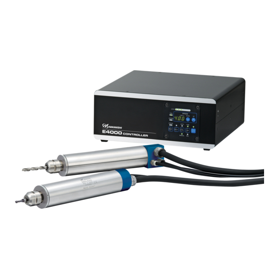
- Page 1 E4000 CONTROLLER 取扱説明書 / OPERATION MANUAL 日本語 : P1 - P46 / English : P49 - P100 OM-K0596 004...
-
Page 2: Table Of Contents
CONTENTS IMPORTANT INSTRUCTIONS AND WARNINGS - Electric Devices …………………………………………… P 50 1 . CAUTIONS FOR HANDLING AND OPERATION ……………………………………………………………… P 2 . BASIC PACKAGE …………………………………………………………………………………………………… P 3 . WARRANTY ………………………………………………………………………………………………………… P 4 . CONTACT US ………………………………………………………………………………………………………… P 5 . FEATURES ……………………………………………………………………………………………………………... -
Page 3: Important Instructions And Warnings - Electric Devices
10A current capacity. 21 . When use the Safety Relay Box, connect the Safety Relay Box to the E4000 CONTROLLER. By doing this, the outer box of Safety Relay Box is grounded and the system will be protected against electric shock. -
Page 4: Cautions For Handling And Operation
This system utilizes air to cool the motor and purge the spindle. Please use an NAKANISHI Air Line Kit to ensure clean, dry, properly regulated air is supplied to the motor and spindle. The E4000 system is capable of being used with coolants and cutting lubricants. - Page 5 WARNING ⑥ Do not use in dangerous environments. Protect the CONTROLLER from moisture and other contaminants. Failure to protect CONTROLLER can result in damage to internal components and injury to the operator. ⑦ To protective CONTROLLER or electric wiring from a possible short circuit, place a circuit breaker (MCCB) between the power source and the AC Power Input Terminal Block of the CONTROLLER.
- Page 6 CAUITION ⑮ Connect the round terminal lugs of the Power Cord to the AC Power Input Terminal Block of the CONTROLLER securely rmly. ⑯ When using in a place where the power conditions are poor, take measures to enable a supplied input power within the speci ed voltage uctuation.
-
Page 7: Basic Package
When opening the package, check if it includes all items listed in " Table 1. Packing List Contents ". In the event of any shortage, please contact either NAKANISHI (see the " 4. CONTACT US " section) or your lo- cal dealer. -
Page 8: Contact Us
: 800-585-4675 Telephone No. : 847-843-7664 Fax No. : 847-843-7622 Web Address : www.nskamericacorp.com For Other Markets Company Name Business Hours : 8:00am to 17:00pm (closed Saturday, Sunday and Public Holidays) Telephone No. : +81 (0) 289-64-3520 e-mail Address : webmaster-ie@nsk-nakanishi.co.jp... -
Page 9: Features
⑮ In an Emergency Stop condition, the power to the motor can be securely disconnected via a relay by using the E4000 Safety Relay Box. A safety system between the E4000 CONTROLLER and the machine can be con gured by utilizing auxiliary contacts. - Page 10 (rpm) speci cation: BMS-4040, BMS-4040RA, BMS-4040-MQL (2M), BMS-4040-MQL-CHK (2M), EM-4040, EM-4040A 6 - 2 Compatibility (1) The E4000 CONTROLLER is compatible with the following overseas safety standard. ・ Safety standard in North America (UL,CSA) UL508C CSA C22.2 No. 14 - 05 ・...
- Page 11 6 - 3 Outside View of the CONTROLLER CAUTION Do not stack 2 CONTROLLERs on top of each other. This will increase the heat generated inside the CONTROLLERS, leading to a premature failure. *Below is an outside view with the Brackets attached (Standard Accessory). Fig.
-
Page 12: System Chart
7 . SYSTEM CHART E4000 CONTROLLER can be used in the following the systems (Fig. 3). 20,000min (rpm) - 40,000min (rpm) Spindle Brushless Motor NR - 4040 EM- 4020 / 4040 Compressor Motor Cord Air Line Kit (Motor Power Line) -
Page 13: Parts Names
9 . PARTS NAMES 9 - 1 System ⑧ ⑨ ⑦ ⑥ ⑤ ① ③ ④ ② ⑪ ⑮ ⑭ ⑬ ⑫ ⑩ Fig. 6 Fig. 7 ① CONTROLLER ② Control Panel Refer to P62 " 9 - 2 Control Panel Details " section. ③... - Page 14 ⑪ AC Power Input Terminal Block The AC Power Input Terminal Block connects to the Power Cord terminals. Refer to P65 " 11. POWER CORD CONNECTION " section. DANGER ・ Make sure the input power supply is OFF before wiring. If the incoming power supply is ON, it may cause risk that leads to death or serious injury by electric shock.
- Page 15 9 - 2 Control Panel Details ⑯ Digital Speed Indicator ⑯ ⑰ ⑱ Preset Speed, Actual Speed, Warning and Error Codes are displayed in 3 digits format. When the motor is stopped the Preset Speed is displayed, when the motor is ㉖...
-
Page 16: Bracket And Rubber Pad Installation
10 . BRACKET AND RUBBER PAD INSTALLATION 10 - 1 Installation of the Brackets CAUTION ・ If there is a possibility for the CONTROLLER from its mounting location, be sure to secure it with the Provided Brackets for safety. ・ When mounting the Bracket, do not loosen any other screws other than the Mounting Screws that are meant to install the Bracket. - Page 17 (2) Side Surface Mounting ① Remove the Mounting Screws (4pcs.) from side of the CONTROLLER (Fig. 9). ② Install the Brackets (2pcs.) to the side of CONTROLLER by using removed Mounting Screws (4pcs.) (Fig. 12). ③ Attach the CONTROLLER (Bracket's Slotted Area) to the machine using the mounting screws (8 pcs.
-
Page 18: Power Cord Connection
11 . POWER CORD CONNECTION DANGER ・ NAKANISHI warns all end-users not to remove the CONTROLLER's Protective Covers A and B while the Control Power is ON, or there is power to the main power cord. Disconnect the main power from its power source before removing the Protective Covers A and B. Not following these instructions may lead to serious injury or death due to electric shock. -
Page 19: Motor Cord Connection
12 . MOTOR CORD CONNECTION CAUTION ・ Before connecting to the Motor Cord Plug (For Power Line / Signal Line), make sure the Main Power Switch is turned OFF. If the Main Power Switch is turned ON while connecting the Motor Cord Plug (For Power Line / Signal Line), damage may occur to the CONTROLLER . -
Page 20: Air Hose Connection
13 . AIR HOSE CONNECTION CAUTION When not using NAKANISHI Air Line Kit, make sure that the incoming air supply is dry, clean and properly regulated. (1) Insert the provided 6mm Air Hose (2m) with Filter (CONTROLLER's standard accessories) from the Air Line Kit into the Air Input Joint on the rear of the CONTROLLER . -
Page 21: Changing The Control Panel
14 . CHANGING THE CONTROL PANEL WARNING Make sure the input power supply is OFF before rotating the direction of setting Control Panel. If the incoming power supply is ON, it may cause electric shock or damage to the CONTROLLER. The position of the Control Panel can be changed from the front to rear of the CONTROLLER. -
Page 22: Operation Procedures
15 . OPERATION PROCEDURES 15 - 1 Selecting Control Mode (MANUAL / AUTO). (Select the control button (CTRL) 24 .) ㉑ of the Fig. ⑯ ⑱ (1) Using the CONTROL (CTRL) Button you can select between Manual (Front panel control) or Auto (External Signal Source) modes. External Signal Source can be used to control Motor Start / Stop, Rotation Direction, Motor Speed etc. - Page 23 (3) Motor Start / Stop Input the Motor Start Signal (Pin No. 14: START). Motor rotating is " ON " (Close). When startup, START / STOP LED of the CONTROLLER will light and motor will rotate. (4) Setting the Motor Speed Motor Speed Range is 1,000 - 40,000 min (rpm).
-
Page 24: External Input / Output Connector
16 . EXTERNAL INPUT / OUTPUT CONNECTOR 16 - 1 External Input / Output Connector A (1) Details of External Input / Output Connector A Signals WARNING ・ DO NOT connect any circuit other than SELV (DC+24V) (Safety Extra Low Voltage) to the External Input / Output Connector A of the CONTROLLER. - Page 25 Input / Code Function Description Output Error Output OFF (Open) : Error Output shows that error has occurred. ON (Closed) : Normal Error code will be displayed on Digital Speed Indicator. When setting parameter , Error Output Mode can be changed. (Refer to P90 "...
- Page 26 Input / Code Function Description Output Power source to be used for External COM_2 External Power Input DC 0V or DC+24V outputs. (Not included / prepared by the Source for end-user) External Output PULSE Rotating Pulse Output 1 pulse / rotation Output 1 pulse / rotation 1 revolution of the motor generates one pulse.
- Page 27 (2) Input / Output Diagram COM _ 1 (DC+24V or DC 0V) START DIR _ OUT DIR _ IN RESET WARNING 500min - (rpm) COIN Input / Output SEL0 Connector (D-Sub25) SEL1 PULSE COM _ 2 UD _ IN (DC 0V or DC+24V) CNT _ IN MOTOR _ I DC+10V...
- Page 28 (3) Input / Output Signal ① Input Signal There are 8 different input signals : " Rotate Command (START) ", " Rotating Direction Setting (DIR_IN) ", " Rotates Motor at ' Centering ' Rotation Speed (500min (rpm)) ", " Error Release (RESET) ", " Count Pulse Signal for Setting Motor Speed (CNT_IN) ", "...
- Page 29 ③ Output Signal Ⅱ Refer to Fig. 28 regarding the Output Signal of the " Rotating Pulse (Pulse) ". The output signal can be connected for either sinking or sourcing. Voltage and Current Speci cations ・Applied Voltage (V) ≦ DC+30V ・Working Current (lp) ≦...
- Page 30 E4000 Motor Speed Control Voltage (VR) vs Motor Speed (1.5) (0.5) Motor Speed Control Voltage (VR) Motor Speed Control Voltage ( VR ) Max.40,000min (rpm) :Motor Speed (min (rpm)) = × 10000 Motor Speed Control Voltage ( VR) Max.20,000min (rpm) :Motor Speed (min (rpm)) =...
- Page 31 16 - 2 External Input / Output Connector B (1) Details of External Input / Output Connector B Signals WARNING ・ DO NOT CONNECT any circuit other than SELV (DC+24V) (Safety Extra Low Voltage) to the External Input / Output Connector B of the CONTROLLER, this will cause I / O board damage in the CONTROLLER.
- Page 32 Input / Code Function Description Output Not Used ― ― ― *Note : Never use pin labeled " NOT USED " Not Used ― ― ― *Note : Never use pin labeled " NOT USED " EMG - INB Emergency Input External Power External Power Source input for Stop B...
- Page 33 (2) Input / Output Signals ① Output Signal (Pin No. 2 - No. 10, No. 5 - No. 13, No. 6 - No. 14) There are 3 kinds of output signals : " Motor Signal Connect Contact (MT - CN) ", " Control Mode AUTO (AUTO) ", and "...
- Page 34 ・ The voltage / current speci cations of No. 3 (SAFE - 1A) - Pin No. 11 (SAFE - 1B) and Pin No. 4 (SAFE - 2A) - Pin No. 12 (SAFE - 2B). ・Applied Voltage (V) ≦ DC+30V ・Working Current (Ip) ≦ 2A ・...
- Page 35 16 - 3 External Input / Output Connector Speci cations CAUTION ・ To minimize RF interference and noise, please keep the length of the cables as short as possible and route them separately or as far away as possible from high voltage electrical cables. ・...
-
Page 36: Protect Function
17 . PROTECT FUNCTION 17 - 1 WARNING FUNCTION CAUTION When the warning LED on the CONTROLLER blinks, conditions exist that could result in dangerous operation. Check operating conditions and continue to use only after correcting the problem. Always check the CONTROLLER, Motor Spindle and the condition of the cooling air prior to use. This will help prevent system errors that will result in non-operational conditions. - Page 37 17 - 3 Resetting System after Error Code There are 2 methods of releasing Error Code. (1) When the control is in MANUAL Mode: Push the Error Reset Button (RESET) of the Control Panel. (2) When the control is in AUTO Mode: Toggle the signal on Pin No.
- Page 38 Indicator. ・ When an error occurs due to internal damage of the CONTROLLER, the Error Signal can not be reset. Please send the Motor spindle and CONTROLLER to a NAKANISHI dealer for repair. Error Code " EF1 " ・ The FAN (80 Square Type) located on the rear of the Control Panel of the CONTROLLER has malfunctioned and stopped.
-
Page 39: Setting Of Operating Parameters
18 . SETTING OF OPERATING PARAMETERS 18 - 1 Entering Parameter Setting Mode CAUTION ・ When in the parameter mode, normal operation of starting, stopping, etc. operation is not possible. ・ When changing from the parameter mode to normal operation, be sure to toggle the Main Power Switch OFF and ON again. - Page 40 18 - 3 Contents of Parameters CAUTION The operating parameters can be preset depending on the application requirements. The operating parameter presets ( " Setting of Error Output Mode ", " Setting AUTO mode for Motor Speed Control ", " Setting Fixed Motor Speed ", " Setting Maximum Motor Speed ", " Selection of External Speed Control Mode ", "...
- Page 41 Setting Maximum Motor Speed ④ CAUTION Actual motor rotation speed of the motor will be limited, based on maximum motor rotation speed of the type of motor connected. ・Maximum Motor Speed can be set. ・Allows a safe maximum rotational speed limit depending on the application. ・The Maximum Motor Speed can set by Control Mode MANUAL or AUTO.
- Page 42 Selection of External Motor Start Signal Control Mode ⑥ ・During Auto Control Mode the motor Start signal can either by a direction signal and a Start signal or a FWD. Start and a REV. Start signal. ・When in Auto Control Mode, the Motor Start Signal can be used for either forward or reverse direction by commanding a Direction Signal and a Start Signal.
- Page 43 Temporary Motor / Spindle Operation if the FAN has stopped (80 Square Type) ⑧ CAUTION Set Parameter , after replacing the FAN (80 Square Type). When FAN (80 Square Type) is operating normally, and parameter is set to , the Error Code " EFP " will be displayed. If FAN (80 Square Type) has stopped due to a malfunction, the motor / spindle can be temporarily operated by setting parameter , until replacment the FAN (80 Square Type) has been completed.
- Page 44 Setting AUTO Mode for Motor Speed Control ② 1. Push the Start / Stop Button (START / STOP). Procedure is displayed. This indicates that speed control by the Motor Speed Adjustment Button (SPEED ) is disabled. The External Command Signal Control will be operational. 3.
- Page 45 Selection of External Speed Control Mode ⑤ CAUTION Actual motor rotation speed of the motor will be limited, based on maximum motor rotation speed and the type of motor connected. 1. Push the Start / Stop Button (START / STOP). Procedure is displayed.
- Page 46 Selection of External Motor Start Signal Control Mode ⑥ 1. Push the Start / Stop Button (START / STOP). Procedure is displayed. This indicates that motor startup and setting the rotation direction can not performed simultaneously. 3. Push the Start / Stop Button (START / STOP). is displayed.
-
Page 47: Control Panel Setting Resume Function
Please refer to the " BREAK IN PROCEDURE " in Operation Manual of the Motor / Spindle. 21 . OPTIONAL DEVICES FOR CONTROLLER 21 - 1 E 4000 SAFETY RELAY BOX When using the E4000 SAFETY RELAY BOX, connect to the E4000 CONTROLLER. (1) Features ① Safety Relay If an "... - Page 48 ② Safety of the Machines when used the Safety Relay Contacts Output ・ When input Emergency Stop Signal that is coupled to opening the movable guard of the Industrial Machinery, Safety Relay will operate and certainly open the Motor Power Line. ・...
-
Page 49: Maintenance
22 - 2 FAN ( 80 Square Type) Replacing Method DANGER NAKANISHI warns all end-users not to replace the E4000 - FAN : FAN (80 Sqare Type) while the Control Power is ON, or if there is power connected to the main power cord. Disconnect the main power from its power source and release the supplied air to the AIR IN quick disconnect before replacing the E4000 - FAN (80 Sqare Type). - Page 50 (4) Remove the Case (Fromt Panel) from the CONTROLLER (Fig. 39). (5) Remove the FAN Cord (Fig. 40). Remove Remove Front Panel Fan Leaded Connentor Fan Leaded Connentor Front Panel Fig. 39 Fig. 40 (6) Remove the FAN Mounting Screws (4pcs.) from the Case (Front Panel) of the CONTROLLER (Fig. 41). (7) Remove the FAN from the Case (Front Panel) of the CONTROLLER (Fig.
- Page 51 If once again Error Code " EF " is displayed on the display of the CONTROLLER, procede no further. As this may cause damage to the FAN or CONTROLLER. Return the CONTROLLER and replacement FAN to an authorized NAKANISHI Dealer Service Center. If Error Code " EFP " is displayed, set Parameter...
-
Page 52: Troubleshooting
22 - 4 Con rmation of Normal Operation Re-supply Air the CONTROLLER. Turn the CONTROLLER's Power Switch ON. Check for normal CONTROLLER functions. ・ If CONTROLLER is not operating normally, the CONTROLLER may be damaged. Return to a NAKANISHI Dealer Service Center. 23 . TROUBLESHOOTING If a problem or concern occurs, please check the following prior to consulting your dealer. -
Page 53: Disposal Of The Controller
Spindle does not rotate or The spindles bearings have been Replace the ball bearings. rotate smoothly. damaged. (Return to NAKANISHI dealer service.) The motor has been damaged. Replace the motor. (Return to NAKANISHI dealer service.) Overheating during Cutting debris has contaminated Replace the ball bearings. - Page 55 2017.11.21 005...
Need help?
Do you have a question about the E4000 CONTROLLER and is the answer not in the manual?
Questions and answers