Table of Contents
Advertisement
Advertisement
Chapters
Table of Contents

Related Manuals for Nakanishi E3000


Summary of Contents for Nakanishi E3000
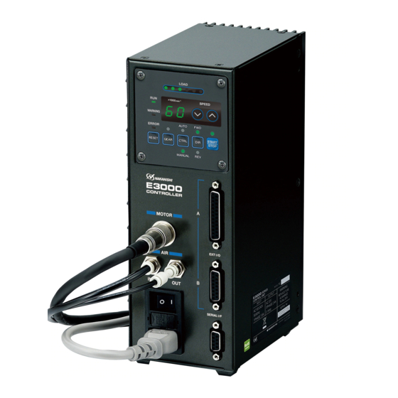
- Page 1 取扱説明書 / OPERATION MANUAL 日本語 : P1 - P44 / English : P47 - P95 OM-K0438 005...
-
Page 2: Table Of Contents
Thank you for purchasing the E 3000 Ultra-Precision, High-Speed spindle system. The E 3000 system was designed for use on CNC lathes, robots, NC lathes and special purpose machines. The motor, spindle and E 3000 CONTROLLER are designed to work as an integrated system capable of 80 , 000 min (rpm). -
Page 3: Important Instructions And Warning - Electric Devices
IMPORTANT INSTRUCTIONS AND WARNING - Electric Devices WARNING! When using electric tools, basic safety precautions should always be followed to reduce the risk of fire, electrical shock and personal injury. Read all these instructions before operating this product and save these instructions. A. -
Page 4: Cautions For Handling And Operation
2 . Replace cracked collet or collet nut immediately. 3 . Do not over tighten the collet nut. 4 . Use only NAKANISHI manufactured collets and arbors for grinding and sawing applications. REMOVE ADJUSTING KEYS AND WRENCHES. Always check to see that keys and adjusting wrenches are removed from tool before turning the units Main Power Switch on. - Page 5 WARNING ① The CONTROLLER is not a hand tool. It is designed to be used on a CNC lathe or special purpose machines. ② Do not touch the cutting tool while the spindle and tool are rotating. It is very dangerous. ③...
- Page 6 ⑰ Do not press the switches on the operation panel of the CONTROLLER with a sharp-pointed tool. ⑱ Don't touch the heat sink of CONTROLLER. This may avoid burns to your skin. ⑲ When using SELECTOR with CONTROLLER, please use E3000 SELECTOR. ⑳ When disposal of a CONTROLLER is necessary, follow the instructions from your local government agency and dispose as an industrial waste.
-
Page 7: Basic Package
When opening the package, check if it includes all items listed in " Table.1 Packing List Contents ". In the event of any shortage, please contact either NAKANISHI (see the " 4. CONTACT US " section) or your local dealer. -
Page 8: Warranty
(closed Saturday, Sunday and Public Holidays) Telephone No. : +81 (0) 289-64-3520 e-mail Address : webmaster-ie@nsk-nakanishi.co.jp 5 . FEATURES 80 , 000 min ① A high-speed brushless motor is used to achieve a maximum speed of (rpm) (when using EM- 3080 J) and eliminate the need for motor brush maintenance. -
Page 9: Specifications And Dimensions
6 . SPECIFICATIONS AND DIMENSIONS 6 - 1 Speci cation of the CONTROLLER Product Name E 3000 CONTROLLER Model NE 211 Input Voltage AC 100 - 240 V, 50 / 60 Hz, 1 PHASE, 1 . 8 A Output AC 33 V, 0 - 1 KHz, 3 PHASE, 2 . 4 A 1 , 000 - 80 , 000 min (rpm) *Note 1 Speed Range... - Page 10 First letter : Other than " D " First letter : " D " 6 - 2 Compatibility (1) The E3000 CONTROLLER is compatible with the following overseas safety standard. ・ Safety standard in North America (UL,CSA) UL508C CSA C22.2 No.14 - 05 ・...
-
Page 11: System Chart
7 . SYSTEM CHART DANGER Do not rotate the machining centers' main spindle with the HES installed. Rotating the machining centers' main spindle with the HES installed can cause the motor cord to become tangled and pull the CONTROLLER off its mounting. (rpm) 7 - 1 Motor Speed 80,000min 1,000 - 80,000min... -
Page 12: Torque Characteristics
( 2 ) Separate Type 60,000min (rpm) Spindle NR-3060S 50,000min (rpm) 1,000 - 60,000min (rpm) (NR-453E) 40,000min (rpm) Spindle NR-453E / NR- 403E (NR-403E) Brushless Motor EM-3060 7,490min (rpm) Motor Cord (Straight Type) EMCD-3000-4M / 6M / 8M 90° Angle Spindle Motor Cord (Angle Type) RAS-151E (1 / 2.67Reduction)... -
Page 13: Control Panel Features
( 3 ) 50 , 000 min (rpm) 25 N - 5000 ① EM ② HES Torque Torque Output Output Continuous Duty Area Continuous Duty Area Continuous Duty Area Continuous Duty Area Speed ( x10 (rpm)) Speed ( x10 (rpm)) Fig. - Page 14 Attach the provided Serial I / F Connector Cover for safety and dust proofing when not using Serial I / F Connector. CAUTION Do not connect any device other than E3000 CONTROLLER to the Serial I / F Connector of the CONTROLLER, as this will cause damage to the CONTROLLER. ⑥ Motor Connector Connect the Motor Cord Plug of the motor spindle.
- Page 15 9 - 2 Control Panel Details ⑫ ⑪ ⑬ ⑳ ⑲ ⑰ ⑱ ⑯ ⑮ ⑭ Fig. 13 ⑪ Digital Speed Indicator Preset Speed, Actual Speed, Warning and Error Codes are displayed in 2 digit format. When the motor is stopped the Preset Speed is displayed, when the motor is rotating the actual speed is displayed.
-
Page 16: Replacing Fuses
⑳ Warning LED (WARNING) The operating and working conditions of the system are constantly monitored and the Warning LED (WARNING) flashes when a hazardous condition has been detected. When a hazardous condition is detected the Warning LED (WARNING) ashes and the Digital Speed Indicator ⑪ alternates between the Warning Code and the actual or preset speed, depending on whether or not the motor / spindle is rotating or not. -
Page 17: Bracket And Rubber Pad Installation
11 . BRACKET AND RUBBER PAD INSTALLATION 11 - 1 Installation of the Bracket CAUTION ・ If there is a possibility for the CONTROLLER to move from its mounting location, for safety, be sure to secure it with the brackets provided. ・... - Page 18 When placing the CONTROLLER horizontally, the Rubber Pads (Provided) must be installed on the side of the air vents. The Control Panel ② can be rotated 90 ° from the original position. To rotate, remove the 4 Control Panel Mounting Screw attached to Control Panel ② . Change position of the Control panel ② and re- install the 4 Control Panel Mounting Screws.
-
Page 19: Power Cord Connection
12 . POWER CORD CONNECTION WARNING Only use grounded power sources. Using a non-speci ed Power Cord, the risk of re by over- heating of the cord is possible. CAUTION ・ Reduce the risk of unintentional starting. Make sure the Main Power Switch ⑨ is in the OFF position before connecting the CONTROLLER or plugging the system in. -
Page 20: Air Hose Connection
14. AIR HOSE CONNECTION CAUTION When not using NAKANISHI Air Line Kit, make sure that the incoming air supply is dry, clean and properly regulated. ( 1 ) Insert the provided 6 mm Air Hose with Filter from the Air Line Kit AL - C 1204 into the Air Input Joint ⑦... -
Page 21: Operation Procedures
15 . OPERATION PROCEDURES 15 - 1 Select Control Mode (MANUAL / AUTO). (Select the Control Button (CTRL) ⑯ of the Fig. 26 . ) ⑪ ⑬ ( 1 ) Using the Control Button (CTRL) ⑯ you can select between Manual (Front panel control) or Auto (External Signal Source) modes. - Page 22 ( 4 ) Motor Start / Stop (Motor Start / Stop by pushing the START / STOP Button (START / STOP) ⑭ of the Fig. 28 .) The motor spindle will start and the LED will illuminate. Push START / STOP Button (START / STOP) ⑭ again and the motor will stop and the LED will go out. ( 5 ) Setting Motor Speed (Set the Motor Speed Adjustment Button (SPEED ) ⑬...
- Page 23 ( 4 ) Motor Start / Stop Input the " Rotate Command (Pin No. 14 : START) ". Motor rotating is ' ON (Closed) '. When startup, RUN LED (RUN) of the CONTROLLER will light and motor will rotate. ( 5 ) Setting the Motor Speed 1 , 000 - 80 , 000 min ・...
-
Page 24: External Input / Output Connector
(7) Set Motor Selection (When connecting the SELECTOR to the CONTROLLER.) After connecting a CONTROLLER to a SELECTOR, 4 motors can be selected by SEL 0 and SEL 1 combination. (Refer to Table. 4 .) Table. 4 Select Motor SEL1 (Pin No.5) SEL0 (Pin No.17) Motor 1 OFF (Open) - Page 25 Input / Code Function Description Output Error Code can be released and the system Error ' ON (Closed) ' → restarted by toggling this signal OFF and RESET Input Release ' OFF (Open) ' ON. Error will not be released until cause of the error has been removed.
- Page 26 Input / Code Function Description Output Motor Start and Motor Stop Signal Setting parameter , can start with Rotate ' OFF (Open) ' : Stop START Input forward rotation. (Refer to P 91 " 18 - 4 ⑥ Command ' ON (Closed) ' : Start Selection of External Motor Start Signal Control Mode"...
- Page 27 Input / Code Function Description Output Shows that the torque being applied to the Torque Load Monitor analog motor. Torque Load LOAD Output (%) = Torque Load 20 % / V 100 % (rating) / DC+ 5 V Monitor Monitor Voltage x 20 Torque Load Monitor : 0 - 200 % ( 0 V ≦...
- Page 28 ( 3 ) Input / Output Signal ① Input Signal There are 8 different input signals : " Rotate Command (START) ", " Rotating Direction Setting (DIR_IN) ", " Rotates Motorat at " Centering " speed ( 500 min (rpm)) ", " Error Release (RESET) ", " UP / DOWN Signal for Setting Motor Speed (UD_IN) ", "...
- Page 29 ④ Motor Speed Control Signal Rotation Speed can be selected by, applying analog voltage to the " Motor Speed Control Voltage (VR) " Refer to Fig. 34 , 35 for connections. Refer to Fig. 36 , 37 for the relationship between Motor Speed and "...
- Page 30 ⑤ Analog Monitor Signals There are 3 types of monitoring signals : " Motor Current Monitor (MOTOR_I) " , " Torque Load Monitor (LOAD) " , and " Rotating Speed Analog Monitor Voltage (SPEED_V) " . Please refer to Fig. 38 for connections.
- Page 31 Input / Code Function Description Output When there is continuity between Pin Pin No. 4 and Pin No. 4 and Pin No. 12 are ' ON (Closed) ' Safety Relay No. 12 continuity SAFE- 2 A Output Safety Relay is OFF (System Stopped), no Contact 2 A ' ON (Closed) ' continuity Safety Relay is ' OFF (Open) '...
- Page 32 Input / Code Function Description Output ' ON (Closed) ' : Main Power Supply CONTROLLER If the Main Power Switch ⑨ is ON, Pin No. is connected ' OFF PWON - Power Source Output (Open) ' : Main 6 and Pin No. 14 are ' ON (Closed) '. Monitor (-) Power Supply is disconnected...
- Page 33 ② Emergency Stop Signal Input Pin No. 1 - 9 This signal is a switched DC+24V output. Please use a separate power source that is capable of applying DC+24V ± 10%, 50mA. Refer to Fig. 40 below for connections. Normal Operation circuit is ' ON (Closed) ' Emergency Stop circuit is ' OFF (Open) '. If the Emergency Stop Signal is ' OFF (Open) ' the Safety Relay is OFF and the power supply to the motor is interrupted and the motor stops.
- Page 34 * Safety Relay If an N - O contact becomes welded, all N - C contacts will maintain a minimum distance of 0 . 5 mm when the coil is not energized. N - O contacts (Normally - opened contacts) : Contacts of U - U , V - V , W - W . N - C contacts (Normally - closed contacts) : Contacts of (SAFE - 1 A) - (SAFE - 1 B), (SAFE - 2 A) - (SAFE - 2 B) * Machine Safety Circuit is possible when using the Safety Relay Contacts Output...
-
Page 35: Protect Function
17 . PROTECT FUNCTION 17 - 1 WARNING FUNCTION CAUTION When the Warning LED (WARNING) ⑳ on the CONTROLLER blinks, conditions exist that could result in dangerous operation. Check operating conditions and continue to use only after correcting the problem. Always check the CONTROLLER, Motor Spindle and the condition of the cooling air prior to use. - Page 36 Error Code is displayed on the Digital Speed Indicator ⑪ . ・ When an error occurs due to internal damage of the CONTROLLER, the Error Signal can not be reset. Please send the Motor spindle and CONTROLLER to a NAKANISHI dealer for repair.
-
Page 37: Setting Of Operating Parameters
If you constantly operate the system in an overload condition, even for short periods of time, the CONTROLLER will overheat and damage to the CONTROLLER, motor and spindle are possible. NAKANISHI recommends only continuous duty operation (LOAD LED's with 3 LED's lit) : Torque Load Monitor (LOAD) Voltage should be less than 5V. - Page 38 Table. 9 Types Default Code Contents Changes the Error Output Signal, when an error occurs Setting of Error Output Mode from normally open to normally closed. When the control is in AUTO mode, the speed Setting AUTO Mode for Motor control is adjustable from the Control Panel ②...
- Page 39 18 - 3 Contents of Parameters CAUTION The operating parameters can be preset depending on the application requirements. The operating parameter presets ( " Setting of Error Output Mode ", " Setting AUTO mode for Motor Speed Control ", " Setting Fixed Motor Speed ", " Setting Maximum Motor Speed ", "...
- Page 40 ④ Setting Maximum Motor Speed ・ Maximum Motor Speed can be set. ・ Allows a safe maximum rotational speed limit depending on the application. ・ The Maximum Motor Speed can set by Control Mode MANUAL or AUTO. Table. 13 Parameter Set Contents Setting of Maximum Motor Speed is enabled.
- Page 41 ⑥ Selection of External Motor Start Signal Control Mode ・ When in Auto Control Mode, the Motor Start Signal can be used for either forward or reverse direction by commanding a Direction Signal and a Start Signal. When set, the rotation direction is controlled by " Rotating Direction Setting (Pin No.
- Page 42 Torque Characteristics.( parameter is 80,000min (rpm) 60,000min (rpm) 50,000min (rpm) 32,000min (rpm) 30,000min (rpm) 0.15 VR (DCV) Motor type Description Max. 80,000min (rpm) DC+9.0V・・・60,000min (rpm) Max. 60,000min (rpm) Max. 50,000min (rpm) DC+7.5V・・・ 50,000min (rpm) Max. 32,000min (rpm) DC+4.8V・・・ 32,000min (rpm) Max.
- Page 43 ⑨ Selection of Emergency Stop Function ・ The Emergency Stop Function can be enabled or disabled. ・ When " Emergency Stop A (Pin No. 1 : EMG - INA) " and " Emergency Stop B (Pin No. 9 : EMG - INB) " of the External Input / Output Connector B ④...
-
Page 44: Procedure
② Setting AUTO Mode for Motor Speed Control Procedure 1 . Push the START / STOP Button (START / STOP) ⑭ . is displayed. This indicates that speed control by the Motor Speed Adjustment Button (SPEED ) ⑬ is disabled. (The External Command Signal Control will be operational.) 3 . -
Page 45: Push The Start / Stop Button (Start / Stop)
⑤ Selection of External Speed Control Mode Procedure 1 . Push the START / STOP Button (START / STOP) ⑭ . is displayed. This indicates that motor rotation speed by Motor Speed Control Voltage is possible. Push the Error Reset Button (RESET) ⑱ to send the settings to memory, will be displayed. - Page 46 ⑥ Selection of External Motor Start Signal Control Mode Procedure 1 . Push the START / STOP Button (START / STOP) ⑭ . is displayed. This indicates that motor startup and setting the rotation direction can not performed simultaneously. 3 . Push the START / STOP Button (START / STOP) ⑭...
-
Page 47: You Can Cycle Through The Choices By Pushing The Start / Stop Button (Start / Stop)
⑨ Selection of Emergency Stop Function Procedure 1 . Push the START / STOP Button (START / STOP) ⑭ . is displayed. This indicates that Emergency Stop Function can not be used. 3 . Push the START / STOP Button (START / STOP) ⑭... -
Page 48: Break In Procedure
20 . Push the Error Reset Button (RESET) ⑱ and will be displayed. 21 . If you desire to set other parameters, push the Motor Speed Adjustment Button (SPEED ⑬ to select the parameter that needs to be set. 22 . When you are nished setting parameters, press the Error Reset Button (RESET) ⑱... - Page 49 Spindle does not The spindles bearings have been damaged. Replace the ball bearings. rotate or rotate (Return to NAKANISHI dealer service.) smoothly. The motor has been damaged. Replace the motor. (Return to NAKANISHI dealer service.)
-
Page 50: Disposal Of The Controller
Replace the collet and the collet nut. Inside of the spindle is worn. Replace the spindle shaft. (Return to NAKANISHI dealer service.) Contaminants inside the collet and the Clean the collet, collet nut and the inside collet nut or the spindle. - Page 51 2017.01.27 03...
Need help?
Do you have a question about the E3000 and is the answer not in the manual?
Questions and answers