
Subscribe to Our Youtube Channel
Related Manuals for Satec C191HM


Summary of Contents for Satec C191HM
- Page 1 C191HM Powermeter Harmonic Manager Installation and Operation Manual BG0280 Rev. A4...
- Page 2 C191HM Powermeter & Harmonic Manager Installation and Operation Manual...
- Page 4 LIMITED WARRANTY The manufacturer offers the customer an 24-month functional warranty on the instrument for faulty workmanship or parts from date of dispatch from the distributor. In all cases, this warranty is valid for 36 months from the date of production.
- Page 5 The secondary of an external current transformer must never be allowed to be open circuit when the primary is energized. An open circuit can cause high voltages, possibly resulting in equipment damage, fire and even serious or fatal injury. Ensure that the current transformer wiring is made through shorting switches and is secured using an external strain relief to reduce mechanical strain on the screw terminals, if necessary.
-
Page 6: Table Of Contents
Table of Contents Quick Start ..................iv Chapter 1 Introduction ..............1 About This Manual.................. 1 About The C191HM ................. 1 Chapter 2 Installation ..............7 Mechanical Installation ................7 Electrical Installation................8 Chapter 3 Using The Menus ............18 Chapter 4 Setup Menus.............. -
Page 7: Quick Start
Quick Start TYPICAL INSTALLATION Wiring Mode 4LL3 (see Section 2.2.4 for full instructions) LINE 1(A) LINE 2(B) LOAD LINE 3(C) Shorting (PLC) Switches RS-485 Powerme ter LOAD UP TO 3 1 DEVICES R S-485 R S-232 A NALOG OUTPUT RELAYS STATUS 2 3 4 5 IN PUT... - Page 8 SETUP (see Chapter 4 for full instructions) Setups can be performed directly on the front panel or via PComTest communication software. menu bASc SELECT ENTER Press ConF option Press to activate middle window. SELECT 4L-n value Press ⇑ ⇓ to scroll to desired option. SELECT Press to activate lower window.
-
Page 10: Chapter 1 Introduction
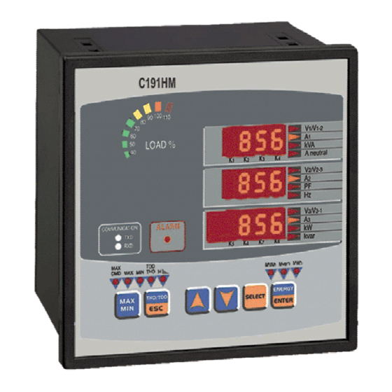
Chapter 1 Introduction 1.1 About This Manual This manual is intended for the user of the C191HM Powermeter. This Powermeter is a microprocessor-based instrument used for the measurement, monitoring, and management of electrical parameters. This chapter gives an overview of this manual and an introduction to the C191HM. - Page 11 screen with a programmable scroll interval of 2 to 15 seconds. Automatic return to the main screen is available after 30 seconds of uninterrupted use. The front panel also includes: • bar graph showing percentage load with respect to user-definable nominal (100%) load current •...
- Page 12 Measured Parameters Note: Real-time values are measured over 1 cycle of fundamental frequency; Average values are of 8, 16 or 32 real-time values Parameter Dis- Output play Analog Pulse Alarm Average Amps, Volts, Frequency $ = setup via PC # = setup via panel √...
- Page 13 Parameter Dis- Output play Analog Pulse Alarm √ √ Total active energy export √ √ Total reactive energy import √ √ Total reactive energy export √ Total reactive energy net Total reactive energy absolute √ √ Total apparent energy Min/Max Log √...
- Page 14 Parameter Dis- Output play Analog Pulse Alarm Individual Harmonic Distortion √ Voltage harmonics 1-40 per phase √ Current harmonics 1-40 per phase √ Odd voltage harmonics 3-39 per phase √ Odd current harmonics 3-39 per phase High odd voltage harmonics 3-39 triggers High odd current harmonics 3-39 triggers √...
- Page 15 Instrument Dimensions 2 - 2 t r a V 2 / 3 - 1 c99-10021/2 Figure 1-1 C191HM Dimensions Chapter 1 Introduction...
-
Page 16: Chapter 2 Installation
Prepare the panel cut-out, 136 x 136 mm, prior to mounting. STEP 1: Place the instrument through the cut-out. STEP 2: Assemble the latches onto the outer wall of the enclosure. STEP 3: Tighten the screws. 6 . 0 c99-09046/2 Figure 2-1 Mounting the C191HM Chapter 2 Installation... -
Page 17: Electrical Installation
Connect the instrument to the current transformer as shown in Figures 2-2 through 2-8. 2.2.3 Ground Connect the chassis ground C191HM terminal to the switchgear earth ground using dedicated wire of greater than 2.5 mm /13 AWG. 2.2.4 Voltage Inputs Input of 690V (Standard): Use any of the seven wiring configurations shown in Figures 2-2 through 2-8. - Page 18 Wiring Wiring Configuration (See parameter setup instructions in Section 4.1) Setup Mode Connection 3-wire direct connection using 2 CTs (2-element) 3dir2 Figure 2-2 4-wire WYE direct connection using 3 CTs (3-element) 4Ln3 or 4LL3 Figure 2-3 4-wire WYE connection using 3 PTs, 3 CTs (3-element) 4Ln3 or 4LL3 Figure 2-4 3-wire open delta connection using 2 PTs, 2 CTs (2-element)
- Page 19 Figure 2-3 LINE 1 (A) LINE 2 LOAD Four Wire WYE Direct LINE 3 Connection Using 3 CTs (3-element) Wiring Mode = 4LL3 Shorting or 4Ln3 Switches Voltages Currents c99-09036 Figure 2-4 LINE 1 LINE 2 LOAD Four Wire WYE LINE 3 Connection Using 3 PTs, 3 CTs (3-...
- Page 20 Figure 2-5 LINE 1 LOAD LINE 2 Three Wire Open LINE 3 Delta Connection Using 2 PTs, 2 CTs (2-element) Wiring Mode = 3OP2 Shorting Switches Voltages Currents c99-09038 Figure 2-6 LINE 1 Three Wire Open LINE 2 LOAD Delta Connection LINE 3 Using 2 PTs, 3 CTs (2½-element)
- Page 21 Figure 2-7 LINE 1 LINE 2 LOAD Four Wire Wye LINE 3 Connection Using 2 PTs, 3 CTs (2½- element) Wiring Mode = 3Ln3 Shorting or 3LL3 Swit ches Voltage s Currents c99-09040 LINE 1(A) 240VAC L (B) LINE 2(B) 120VAC 240VAC LOAD...
- Page 22 2.2.5 Relay Eight relays are provided for energy pulsing, alarms or remote control. C1 91H M CONTR OL R E LAY S 2 0 21 REL AY CONTROL ENABL E/ DISABLE LOAD LOAD LOAD FUSE FUSE FUSE 10 -1 5A 15 A 1 20- 230 V AC 1 2 0-23 0 V AC...
- Page 23 2.2.7 Analog Output The C191HM provides one optically isolated analog output with current output options of 0-20 mA and 4-20 mA (current loop load of up to 500 Ohm). The analog output must be used with a 24 V DC external power supply.
- Page 24 The C191HM is provided with an RS-232 or RS-485 communication port. Connections can be made as follows: RS-232: distance of up to 15 meters, one C191HM to one computer/PLC, using a flat or twisted pair cable of 0.33mm2/22AWG RS-485: distance of up to 1200 meters, up to 32 instruments on one multi-drop...
- Page 25 Activity on the communications port lines is indicated via the TXD and RXD LEDs, on the front panel and via the Status Information menu (see Chapter 6). A full description of the communication protocols may be found in the C191HM ASCII, Modbus and DNP3.0 Communications Manuals provided with your...
- Page 26 instrument. Chapter 2 Installation...
-
Page 27: Chapter 3 Using The Menus
Chapter 3 Using The Menus Press and release SELECT to enter the setup mode. The primary menus will appear: Status Information Menu (see Chapter 6) Setup Options Menu Setup Change Menu (see Chapter 4) Press again to activate the window of the desired primary menu. SELECT Press ENTER... - Page 28 SELECT ENTER Status Information Setup Options ENTER Setup Change Password PASS Reset Functions Phase Rotation PHAS Basic Setup Relay Status bASc Port Setup Status Inputs Port St.In Digital Inputs Counter #1 dinP Cnt.1 Analog Outputs Counter #2 Aout Cnt.2 Pulsing Setpoints Counter #3 PulS Cnt.3...
-
Page 29: Chapter 4 Setup Menus
Chapter 4 Setup Menus 4. CHAPTER 3 SETUP MENUS NOTE: Instrument setup can be performed directly on the front panel using the setup menus or via communications using PComTest communication software. PComTest is supplied with your instrument and provides full setup capabilities for your instrument. For information on using PComTest, refer to the user documentation supplied with your instrument. - Page 30 (0∗) When the power demand period is specified in minutes, synchronization of the demand interval can be made through communications (see the C191HM ASCII/Modbus Reference Guides) or via the front panel (see Section 4.11). If the power demand period is set to External Synchronization, an external synchronization pulse denoting the start of the next demand interval can be provided through a digital input or can be simulated by using the synchronization command sent via communications.
-
Page 31: Communications Port Setup Menu
ENTER This menu allows you to access the communications port options that the C191HM uses to communicate with a master computer. Table 4-2 lists the communications options, their code names and applicable choices. Activate the middle window to scroll through the list of available options, and then activate the lower window to set the option value. -
Page 32: Digital Input Setup Menu
ENTER ENTER This menu is used to set up a digital input provided by the C191HM. The digital input can be configured as: - a status input to monitor external contact status, or - an external synchronization pulse input to receive an external synchronization pulse indicating the beginning of a new demand interval for power demand measurements. -
Page 33: Analog Output Setup Menu
4.4 Analog Output Setup Menu [This section is relevant to instruments ordered with this option.] Aout SELECT ENTER ENTER This menu allows you to set up an output value and its zero and full scales for the internal analog output. Table 4-3 explains the analog output setup options, and Table 4-4 lists all measurement parameters that can be directed to analog output. - Page 34 Table 4-3 Analog Output Setup Options Code Option Description OutP Output parameter The output parameter for the analog output channel Zero scale (0/4 mA) The reading of the parameter corresponding to a zero- scale current output Full scale (1/20 mA) The reading of the parameter corresponding to a full-scale current output Table 4-4 Analog Output Parameters...
-
Page 35: Pulsing Output Setup Menu
ENTER This menu allows you to program any of the eight relays provided by your C191HM instrument to output energy pulses. Relays #7 and #8 are especially recommended for use as pulsing relays because of their high endurance. Available pulsing parameters are listed in Table 4-5. -
Page 36: Alarm/Event Setpoints Setup Menu
NOTES 1. If your instrument is not equipped with the optional relay, then this setup parameter will not appear on the display. 2. You will not be able to store your setup in the instrument if you assigned a parameter to relay output with a zero number of unit-hours per pulse. - Page 37 SP 1 Setpoint action The action to be triggered is operation of relay #1. rEL.1 To select a setpoint: Scroll to the desired setpoint using the up/down arrow keys. To view the setup options for the setpoint: SELECT Press to activate the middle window. Use the up/down arrow keys to scroll to the desired setup option.
- Page 38 Table 4-6 Setpoint Setup Options (middle window) Code Option Description triG Trigger parameter The measurement parameter or signal to be monitored by the setpoint. Operate limit The threshold at which the setpoint becomes operative. Release limit The threshold at which the setpoint is released (becomes inoperative).
- Page 39 Code Parameter Unit Range A. PF.Ld Low total PF Lead 0 to 1.000 Average Auxiliary Measurements Ar neU.C High neutral current 0 to Imax Ar Hi.Fr High frequency 0 to 100.00 Ar Lo.Fr Low frequency 0 to 100.00 Present Demands Hi d.U1 High volt demand L1 0 to Vmax...
- Page 40 Table 4-8 Setpoint Actions (lower window, when middle window is Act) Code Action NonE No action ALAr Assert local alarm rEL.1 Operate relay #1 rEL.2 Operate relay #2 rEL.3 Operate relay #3 rEL.4 Operate relay #4 rEL.5 Operate relay #5 rEL.6 Operate relay #6 rEL.7...
-
Page 41: Relay Operation Control Menu
4.7 Relay Operation Control Menu SELECT rELo ENTER ENTER This menu allows you to set the relay operation mode: non-failsafe or failsafe. Failsafe relay operation is the opposite of normal operation where relay contacts are closed when a relay is operated (activated), and are open when a relay is released (de-activated). -
Page 42: Display Setup Menu
4.8 Display Setup Menu SELECT diSP ENTER ENTER This menu allows you to view and change display properties. Table 4-9 lists available options with their code names and applicable ranges. Table 4-9 Display Options (∗ default setting) Display Code Parameter Options Description UPdt... - Page 43 To select a display option: Press SELECT to activate the middle window, and then use the up/down arrow keys to scroll to the desired option. To change the display option: Press SELECT to activate the lower window. Use the up/down arrow keys to set the desired option. ENTER Press to store your new setting or press...
-
Page 44: User Selectable Options Menu
4.9 User Selectable Options Menu OPtS SELECT ENTER ENTER This menu allows you to change options which relate to the instrument features and functionality. Table 4-10 lists all available options with their code names and applicable ranges. To select an option: OPtS Press SELECT... - Page 45 Energy roll value example: If roll value = 10.E4, the energy counter contains 4 digits, i.e., energy is displayed up to 9.999 MWh (Mvarh, MVAh) with resolution 0.001 MWh. Rollover Maximum Energy Maximum Display Reading Display Resolution Value kWh (kvarh, kVAh) MWh (Mvarh, MVAh) MWh (Mvarh, MVAh) 10.E4...
-
Page 46: Access Control Menu
4.10 Access Control Menu SELECT ENTER AccS ENTER This menu can be only accessed via the Setup Change Menu (CHG). It is used in order to: • change the user password • enable or disable password check To view an option setting: SELECT Press to activate the middle window. -
Page 47: Reset/Synchronization Menu
4.11 Reset/Synchronization Menu SELECT ENTER ENTER This menu allows you to reset to zero the accumulators and Min/Max registers in your instrument, and also to synchronize the power demand interval. The menu can be only accessed via the Setup Change Menu (CHG). If the reset is disabled from the Basic Setup Menu (see Section 4.1), you will not be able to enter this menu. -
Page 48: Chapter 5 Data Display
Chapter 5 Data Display 5.1 Navigating in the Display Mode The front panel has a simple interface that allows you to display numerous measurement parameters in up to 45 display pages. For easier reading, the parameters are divided into three groups, each accessible by a designated key. These are: Common measurements - no selection key... - Page 49 The highest current measured by the C191HM is divided by the nominal load current as defined in the Display Setup Menu (see Section 4.8) and expressed as a percent by the LEDs (40% to 110%) which are lit.
- Page 50 common measurements parameters. Selecting Min/Max Measurements MAX/MIN Press the key. Use the up/down arrow keys to scroll through Min/Max measurements. Selecting Total Harmonic Measurements Press the key until the THD/TDD LED is illuminated. Use the H/ESC up/down arrow keys to scroll through the different harmonic parameters. Selecting Individual Voltage Harmonics Measurements Press the key until the HARMONICS LED is illuminated and volts...
-
Page 51: Data Display Formats
5.2 Data Display Formats Table 5-1 specifies all front panel local displays available in the display mode. The display windows are labeled in the table as follows: 1 = upper window, 2 = middle window, 3 = lower window. Table 5-1 Displayed Parameters Page Window Indicator... - Page 52 Page Window Indicator Parameter Digits Unit H1.L2 Label H01 power factor L2 H01 kW L2 kW/MW H1.L3 Label H01 power factor L3 H01 kW L3 kW/MW U.Unb Label Voltage unbalance C.Unb Label Current unbalance Min/Max Measurements V1/V1-2 Min. real-time voltage L1/L12 V/kV V2/V2-3 Min.
- Page 53 Page Window Indicator Parameter Digits Unit Max. sliding window kW demand kW/MW Total Harmonic Measurements THD/TDD V1/V1-2 Voltage THD L1/L12 V2/V2-3 Voltage THD L2/L23 V3/V3-1 thd. Voltage THD L3 Current THD L1 Current THD L2 thd. Current THD L3 Current TDD L1 Current TDD L2 tdd.
- Page 54 Page Window Indicator Parameter Digits Unit Mvarh rE.En. Label Label Mvarh export Mvarh Phase Energies Ac.En. Label IP.L1 Label MWh import L1 Mvarh rE.En. Label IP.L1 Label Mvarh import L1 Mvarh MVAh AP.En. Label Label MVAh L1 MVAh Ac.En. Label IP.L2 Label MWh import L2...
-
Page 55: Self-Test Diagnostics Display
External reset (warm restart) NOTE The C191HM provides a self-check alarm register accessible through communications that indicates possible problems with instrument hardware or setup configuration. The hardware problems are indicated by the appropriate bits which are set whenever the instrument fails self-test diagnostics or in the event of loss of power. -
Page 56: Chapter 6 Viewing Status Information
Chapter 6 Viewing Status Information Through the Status Information Menu (StA), it is possible to view the status of various instrument features. 6.1 The Status Information Menu SELECT ENTER To enter the Status Information Menu: From the display mode, press to enter the Primary Selection Menu. - Page 57 Table 6-1 Status Information Display Page Window Parameter Digits Unit PHAS Label Label Phase rotation sequence (POS/NEG/ERR) Label Relay #1 - #4 status Relay #5 - #8 status St.In Label Status input Cnt.1 Label Counter #1 Cnt.2 Label Counter #2 Cnt.3 Label Counter #3...
-
Page 58: Appendix: Technical Specifications
Appendix: Technical Specifications 7. ions Input and Output Ratings 3 galvanically 690 V: DIRECT INPUT (690V line-to-line voltage and 400V line- isolated voltage (standard) to-neutral) Burden: <0.5 VA inputs INPUT USING PT Burden: <0.15 VA 120 V: INPUT USING PT (120V line-to-line voltage) Burden: <0.1 VA (optional) 3 galvanically... - Page 59 Environmental Conditions -20°C to +60°C (-4°F to +140°F) Operating temperature -25°C to +80°C (-13°F to +176°F) Storage temperature Humidity 0 to 95% non-condensing Construction Instrument body Case enclosure: flame resistant ABS & Polycarbonate Blend Dimensions: 144 x 144 x 86 mm ( 5.67 x 5.67 x 3.39 “) Mounting: 136 x 136 mm square cut-out (DIN 43700) Instrument weight 0.9 kg (2.04 lb.)
-
Page 63: Index
Index mounting, 1, 7 accuracy, 51 active energy, 3, 51 open delta, 9, 20 active power, 3, 4, 34, 50 options, 14 alarms, 13 overload withstand, 48 ampere demand, 20, 29, 42 analog output, 2, 5, 8, 14, 23, 24 analog outputs, 20 panel cut-out, 7 password, 2, 17, 36, 37, 39, 46...
Need help?
Do you have a question about the C191HM and is the answer not in the manual?
Questions and answers