
Related Manuals for Satec PM180


Summary of Contents for Satec PM180
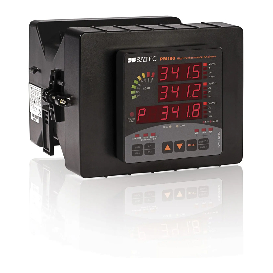
- Page 1 High Performance Analyzer PM180 IEC 61850 Communications Protocol Reference Guide BG0523 Rev. A2...
- Page 2 Every effort has been made to ensure that the material herein is complete and accurate. However, the manufacturer is not responsible for any mistakes in printing or faulty instructions contained in this book. Notification of any errors or misprints will be received with appreciation.
-
Page 3: Table Of Contents
Table of Contents 1 General.......................6 2 ACSI (Abstract Communication Service Interface) Conformance Statement......................7 ACSI basic conformance statement..............7 ACSI models conformance statement ............. 7 ACSI service conformance statement.............. 8 3 MICS - Model Implementation Conformance Statement ......11 Model conformance ..................11 Common data attributes classes.............. - Page 4 Logical node zero LLN0 ..................17 GOOSE subscription status CTRL/sbsLGOS1-sbsLGOS20 ........... 17 3.4.2 Logical nodes for control ................18 Switch controllers CTRL/CSWI1- CSWI16 ............... 18 Switch control interlocking status CTRL/CILO1-CILO16 ..........18 Relay control interlocking status MET1/blkCILO1-blkCILO8........18 3.4.3 Logical nodes for switchgear................19 Circuit breakers CTRL/XCBR1- XCBR2 ..............
- Page 5 Controls ......................40 Measurement units ..................... 40 Process Measurement Limits................. 41 Deadbands ......................41 Textual descriptions .................... 41 6 Configuring IEC 61850..................42 Licensing IEC 61850 ..................42 Configuring IED Properties ................42 Configuring Datasets ..................43 Configuring Report Control Blocks..............45 Configuring the GOOSE Publisher ..............
-
Page 6: General
1 General The PM180 is provided with an embedded IEC 61850 server compliant with the IEC 61850 set of standards. This document contains the IEC 61850 conformance statements that give the summary of the device data object model, protocol implementations and communication capabilities of the PM180. -
Page 7: Acsi (Abstract Communication Service Interface) Conformance Statement
2 ACSI (Abstract Communication Service Interface) Conformance Statement This chapter contains the ACSI conformance statement as defined in Annex A of IEC 61850- 7-2 that specifies the device communication features mapped to an SCSM (Specific Communication Service Mapping). 2.1 ACSI basic conformance statement Services Client/ Server/... -
Page 8: Acsi Service Conformance Statement
Services Client/ Server/ Value/ Subscriber Publisher Comments M8-5 data-reference M8-6 BufTm M8-7 IntgPd M8-8 Logging Log control M9-1 IntgPd Control If GSE (B31/B32) is supported GOOSE M12-1 entryID M12-2 DataRefInc GSSE If SVC (B41/B42) is supported Multicast SVC Unicast SVC Time Time source with required accuracy shall be available... - Page 9 Services Client/ Server/ Comments TP/MC Subscriber Publisher Setting group control (Clause 13) SelectActiveSG SelectEditSG SetSGValues ConfirmEditSGValues GetSGValues GetSGCBValues Reporting (Clause 14) Buffered report control block (BRCB) Report S24-1 data-change (dchg) S24-2 qchg-change (qchg) S24-3 data-update (dupd) GetBRCBValues SetBRCBValues Unbuffered report control block (URCB) Report S27-1 data-change (dchg)
- Page 10 Services Client/ Server/ Comments TP/MC Subscriber Publisher Operate Command-Termination For CSWI class nodes TimeActivated-Operate File transfer (Clause 20) GetFile SetFile DeleteFile GetFileAttributeValues Time (Clause 18) Time resolution of internal clock n=10 (T1) (nearest value of 2**-n in seconds) Time accuracy of internal clock n=10 (T1) Supported TimeStamp resolution n=10 (T1)
-
Page 11: Mics - Model Implementation Conformance Statement
This chapter contains the MICS conformance statement as required by IEC 61850-10. It lists data object model elements supported by the PM180 and provides definitions of the logical nodes, common data classes and data attribute types as defined in IEC 61850-7-3 and IEC 61850-7-4. -
Page 12: Pulse Configuration
Pulse configuration Attribute Name Attribute Type Value/Range M/O/C Comments cmdQual ENUMERATED pulse | persistent For boGGIO pulse output, a relay must be set to pulse mode via the device Relay Setup onDur INT32U boGGIO class nodes: default = 2000 ms CSWI class nodes: default = 0 offDur... -
Page 13: Common Data Classes
3.3 Common data classes The following tables indicate mandatory, conditional and optional attributes of each Common Data Class (CDC) that are supported by the PM180. Mandatory attributes (M) are always present. Single point status (SPS) Attribute Name Attribute Type M/O/C... -
Page 14: Complex Measured Value (Cmv)
Attribute Name Attribute Type M/O/C Comments the AnalogueValue may be present for a given instance of DATA Quality TimeStamp units Unit INT32U VISIBLE STRING64 Complex measured value (CMV) Attribute Name Attribute Type M/O/C Comments cVal Vector Quality TimeStamp units Unit INT32U VISIBLE STRING64 Sampled value (SAV) -
Page 15: Harmonic Value For Del (Hdel)
Attribute Name Attribute Type M/O/C Comments numCyc INT16U numCyc = 1 units Unit evalTm INT16U evalTm = nominal period frequency FLOAT32 frequency = nominal frequency VISIBLE STRING64 Harmonic value for DEL (HDEL) Attribute Name Attribute Type M/O/C Comments Quality TimeStamp phsABHar ARRAY[0..numHar] OF Vector... -
Page 16: Controllable Integer Status (Inc)
subVal CODED ENUM PICS_SUBST subQ Quality PICS_SUBST pulseConfig PulseConfig ctlModel CtlModels VISIBLE STRING64 Controllable integer status (INC) Attribute Name Attribute Type M/O/C Comments ctlVal INT32 stVal INT32 Quality TimeStamp VISIBLE STRING64 Binary controlled step position information (BSC) Common data class is not supported. Binary controlled step position information (ISC) Common data class is not supported. -
Page 17: Curve Shape Description (Csd)
Metering, measurements and general digital input and output elements Logical devices contain logical nodes LPHD and LLN0 dedicated to the PM180 unit, and a set of functional logical nodes for functions supported by the PM180. Logical node names are fixed. -
Page 18: Logical Nodes For Control
Attribute name Attribute Explanation/Value M/O/C/E Comments type number 3.4.2 Logical nodes for control Switch controllers CTRL/CSWI1- CSWI16 Attribute name Attribute Explanation/Value M/O/C/E Comments type LNName Object name CSWI1…CSWI16 A configurable prefix can be added to a LNName via the device Bay Control Setup Common Logical Node Information Mode Behavior... -
Page 19: Logical Nodes For Switchgear
Attribute name Attribute Explanation/Value M/O/C/E Comments type Relay outputs RO9-RO16 (blkCILO2) Relay setup. A relay can Relay outputs RO17-RO24 (blkCILO3) only be unblocked via a Relay outputs RO25-RO32 (blkCILO4) control setpoint. Relay outputs RO33-RO40 (blkCILO5) Relay outputs RO41-RO48 (blkCILO6) Relay outputs RO49-RO56 (blkCILO7) Relay outputs RO57-RO64 (blkCILO8) 3.4.3 Logical nodes for switchgear Circuit breakers CTRL/XCBR1- XCBR2... -
Page 20: Logical Nodes For Generic Reference
Attribute name Attribute Explanation/Value M/O/C/E Comments type Mode Behavior Health Health NamePlt Name plate Status Information RcdMade Recording made Set to TRUE when at least one disturbance waveform is available for a read. FltNum Fault number Indicates the last waveform series number available in a disturbance recorder. -
Page 21: Event Flags Met1/Evfggio1 - Evfggio2
Attribute name Attribute Explanation/Value M/O/C/E Comments type Local operation Controls SPCSO1…SPCSO8 Single point controllable status output: Relay outputs RO1-RO8 (boGGIO1) Relay outputs RO9-RO16 (boGGIO2) Relay outputs RO17-RO24 (boGGIO3) Relay outputs RO25-RO32 (boGGIO4) Relay outputs RO33-RO40 (boGGIO5) Relay outputs RO41-RO48 (boGGIO6) Relay outputs RO49-RO56 (boGGIO7) Relay outputs RO57-RO64 (boGGIO8) Event flags MET1/evfGGIO1 –... -
Page 22: Logical Nodes For Metering And Measurement
3.4.6 Logical nodes for metering and measurement Energy counters MET1/engMMTR1 Attribute name Attribute Explanation/Value M/O/C/E Comments type LNName Object name engMMTR1 Common Logical Node Information Mode Behavior Health Health NamePlt Name plate Measured values TotVAh Apparent energy Total TotWh Net real energy TotVArh Net reactive energy SupWh... -
Page 23: Total Harmonics Met1/Ocvmhai1
Attribute name Attribute Explanation/Value M/O/C/E Comments type HPPV HDEL Sequence of harmonics phase to In 4LL3, 3LL3, 3BLL3, phase voltages 3DIR2, 3OP2 and 3OP3 wiring modes Total harmonics MET1/ocvMHAI1 Attribute name Attribute Explanation/Value M/O/C/E Comments type LNName Object name ocvMHAI1 Common Logical Node Information Mode Behavior... -
Page 24: Sliding Power Demands Met1/Demmmxu2
Attribute name Attribute Explanation/Value M/O/C/E Comments type Phase and neutral current (*) See WYE demands TotkWImp Total active power imported block demand TotkWExp Total active power exported block demand TotkVarImp Total reactive power imported block demand TotkVarExp Total reactive power exported block demand TotVA Total apparent power demand... -
Page 25: Predicted Power Demands Met1/Demmmxu4
Predicted power demands MET1/demMMXU4 Attribute name Attribute Explanation/Value M/O/C/E Comments type LNName Object name demMMXU4 Common Logical Node Information Mode Behavior Health Health NamePlt Name plate Measured values TotkWImp Total active power imported predicted demand TotkWExp Total active power exported predicted demand TotkVarImp Total reactive power imported... -
Page 26: Phasors Met1/Phsrmmxu1
Attribute name Attribute Explanation/Value M/O/C/E Comments type TotW Total active power TotVAr Total reactive power TotVA Total apparent power TotPF Total power factor TotPFLag Total power factor lag TotPFLead Total power factor lead TotkWImp Total active power imported TotkWExp Total active power exported TotkVarImp Total reactive power imported TotkVarExp... -
Page 27: One-Cycle Imbalance Met1/Ocvmsqi1
Attribute name Attribute Explanation/Value M/O/C/E Comments type SeqExtA Zero sequence current, extended inputs Ix ImbNgV Imbalance negative sequence voltage ImbNgA Imbalance negative sequence current ImbNgExtA Imbalance negative sequence current, extended inputs Ix One-cycle imbalance MET1/ocvMSQI1 Attribute name Attribute Explanation/Value M/O/C/E Comments type LNName... - Page 28 Attribute name Attribute Explanation/Value M/O/C/E Comments type MinPPV Minimum voltage phase to phase MinAmps Minimum current MinW Minimum phase real power MinVAr Minimum phase reactive power MinVA Minimum phase apparent power MinPFLag Minimum phase PF lag MinPFLead Minimum phase PF lead MinThdPhV Minimum voltage THD phase to ground...
-
Page 29: Pics - Protocol Implementation Conformance Statement
4 PICS – Protocol Implementation Conformance Statement This chapter contains the PICS conformance statement as defined by IEC 61850-8-1 that specifies mapping to MMS and to ISO/IEC 8802-3. 4.1 Profile conformance A-Profile support Profile Profile description type Client/ Server/ Comments Subscriber Publisher Client/server... - Page 30 MMS service supported CBB (server) M/O/C/I Supported initiateUploadSequence uploadSegment terminateUploadSequence requestDomainDownload requestDomainUpload loadDomainContent storeDomainContent deleteDomain getDomainAttributes createProgramInvocation deleteProgramInvocation start stop resume reset kill getProgramInvocationAttributes obtainFile defineEventCondition deleteEventCondition getEventConditionAttributes reportEventConditionStatus alterEventConditionMonitoring triggerEvent defineEventAction deleteEventAction alterEventEnrollment reportEventEnrollmentStatus getEventEnrollmentAttributes acknowledgeEventNotification getAlarmSummary getAlarmEnrollmentSummary readJournal writeJournal initializeJournal reportJournalStatus...
-
Page 31: Goose Conformance Statement (Goose Services)
MMS service supported CBB (server) M/O/C/I Supported deleteAccessControlList alterAccessControl reconfigureProgramInvocation M: mandatory support O: optional support C: conditional support I: out of scope NP: not present (MMS minor version 1 compatibility) 4.3 GOOSE conformance statement (GOOSE Services) Service Subscriber Publisher Value/comments SendGOOSEMessage GetGoReference... -
Page 32: Pixit - Protocol Implementation Extra Information For Testing
5 PIXIT - Protocol Implementation Extra Information for Testing This chapter describes device specific implementation of the protocol and communication capabilities of the PM180. 5.1 Device configuration The device configuration except of the listed items cannot be modified and is listed for information only. -
Page 33: Dataset Model
Dataset model Item Value/Comments Predefined Datasets in ICD file Measurand data: MET1/LLN0$DSet01Mx MET1/LLN0$DSet02Mx MET1/LLN0$DSet03Mx MET1/LLN0$DSet04St MET1/LLN0$DSet05Mx Status data: MET1/LLN0$DSet01StInd MET1/LLN0$DSet02StInd MET1/LLN0$DSet03StInd MET1/LLN0$DSet04StInd MET1/LLN0$DSet04StSPCSO MET1/LLN0$DSet05StSPCSO MET1/LLN0$DSet06StSPCSO MET1/LLN0$DSet07StSPCSO MET1/LLN0$DSet08StInd MET1/LLN0$DSet09StInd MET1/LLN0$DSet09StFltNum GOOSE publisher data set: CTRL/LLN0$DSetGOOSE1 Maximum number of data elements in one Dataset Maximum number of persistent Datasets 17 predefined + 16 deletable Predefined Dataset members... - Page 34 Data Set name Members MET1/LLN0$osvMMXU1$MX$ExtA$phsC MET1/LLN0$osvMMXU1$MX$ExtAuxA MET1/LLN0$osvMMXU1$MX$AvExtA MET1/LLN0$DSet01StInd MET1/LLN0$biGGIO1$ST$Ind1 MET1/LLN0$biGGIO1$ST$Ind2 … MET1/LLN0$biGGIO1$ST$Ind16 MET1/LLN0$biGGIO2$ST$Ind1 MET1/LLN0$biGGIO2$ST$Ind2 … MET1/LLN0$biGGIO2$ST$Ind16 MET1/LLN0$DSet02StInd MET1/LLN0$biGGIO3$ST$Ind1 MET1/LLN0$biGGIO3$ST$Ind2 … MET1/LLN0$biGGIO3$ST$Ind16 MET1/LLN0$biGGIO4$ST$Ind1 MET1/LLN0$biGGIO4$ST$Ind2 … MET1/LLN0$biGGIO4$ST$Ind16 MET1/LLN0$DSet03StInd MET1/LLN0$biGGIO5$ST$Ind1 MET1/LLN0$biGGIO5$ST$Ind2 … MET1/LLN0$biGGIO5$ST$Ind16 MET1/LLN0$biGGIO6$ST$Ind1 MET1/LLN0$biGGIO6$ST$Ind2 … MET1/LLN0$biGGIO6$ST$Ind16 MET1/LLN0$DSet04StInd MET1/LLN0$biGGIO7$ST$Ind1 MET1/LLN0$biGGIO7$ST$Ind2 … MET1/LLN0$biGGIO7$ST$Ind16 MET1/LLN0$biGGIO8$ST$Ind1 MET1/LLN0$biGGIO8$ST$Ind2 …...
-
Page 35: Reporting Model
Data Set name Members MET1/LLN0$DSet08StInd MET1/LLN0$spGGIO1$ST$Ind1 MET1/LLN0$spGGIO1$ST$Ind2 … MET1/LLN0$spGGIO1$ST$Ind32 MET1/LLN0$DSet09StInd MET1/LLN0$spGGIO2$ST$Ind1 MET1/LLN0$spGGIO2$ST$Ind2 … MET1/LLN0$spGGIO2$ST$Ind32 MET1/LLN0$DSet09StFltNum MET1/LLN0$drRDRE1$ST$FltNum MET1/LLN0$drRDRE2$ST$FltNum … MET1/LLN0$drRDRE8$ST$FltNum CTRL/LLN0$DSetGOOSE1 CTRL/QA1XCBR1$ST$Pos$stVal CTRL/QA1XCBR1$ST$Pos$q CTRL/QA2XCBR2$ST$Pos$stVal CTRL/QA2XCBR2$ST$Pos$q CTRL/QB1XSWI1$ST$Pos$stVal CTRL/QB1XSWI1$ST$Pos$q CTRL/QB2XSWI2$ST$Pos$stVal CTRL/QB2XSWI2$ST$Pos$q CTRL/QB3XSWI3$ST$Pos$stVal CTRL/QB3XSWI3$ST$Pos$q CTRL/QB4XSWI4$ST$Pos$stVal CTRL/QB4XSWI4$ST$Pos$q CTRL/QB5XSWI5$ST$Pos$stVal CTRL/QB5XSWI5$ST$Pos$q CTRL/QB6XSWI6$ST$Pos$stVal CTRL/QB6XSWI6$ST$Pos$q CTRL/QE1XSWI7$ST$Pos$stVal CTRL/QE1XSWI7$ST$Pos$q CTRL/QE2XSWI8$ST$Pos$stVal CTRL/QE2XSWI8$ST$Pos$q CTRL/QE3XSWI9$ST$Pos$stVal CTRL/QE3XSWI9$ST$Pos$q CTRL/QE4XSWI10$ST$Pos$stVal... - Page 36 Item Value/Comments MET1/LLN0$RP$URep05 MET1/LLN0$RP$URep06 MET1/LLN0$RP$URep07 MET1/LLN0$RP$URep08 16 BRCBs: CTRL/LLN0$BR$BRep01 CTRL/LLN0$BR$BRep02 CTRL/LLN0$BR$BRep03 CTRL/LLN0$BR$BRep04 CTRL/LLN0$BR$BRep05 CTRL/LLN0$BR$BRep06 CTRL/LLN0$BR$BRep07 CTRL/LLN0$BR$BRep08 MET1/LLN0$BR$BRep01 MET1/LLN0$BR$BRep02 MET1/LLN0$BR$BRep03 MET1/LLN0$BR$BRep04 MET1/LLN0$BR$BRep05 MET1/LLN0$BR$BRep06 MET1/LLN0$BR$BRep07 MET1/LLN0$BR$BRep08 Number of RCB instances = 1 (indexed RCBs, RptEnabled max=1) 16 URCBs: CTRL/LLN0$RP$URepA01 CTRL/LLN0$RP$URepB01 CTRL/LLN0$RP$URepC01 CTRL/LLN0$RP$URepD01 CTRL/LLN0$RP$URepE01 CTRL/LLN0$RP$URepF01 CTRL/LLN0$RP$URepG01...
- Page 37 Item Value/Comments MET1/LLN0$RP$URepA02 MET1/LLN0$RP$URepB01 MET1/LLN0$RP$URepB02 MET1/LLN0$RP$URepC01 MET1/LLN0$RP$URepC02 MET1/LLN0$RP$URepD01 MET1/LLN0$RP$URepD02 8 BRCBs x 2 clients: CTRL/LLN0$BR$BRepA01 CTRL/LLN0$BR$BRepA02 CTRL/LLN0$BR$BRepB01 CTRL/LLN0$BR$BRepB02 CTRL/LLN0$BR$BRepC01 CTRL/LLN0$BR$BRepC02 CTRL/LLN0$BR$BRepD01 CTRL/LLN0$BR$BRepD02 MET1/LLN0$BR$BRepA01 MET1/LLN0$BR$BRepA02 MET1/LLN0$BR$BRepB01 MET1/LLN0$BR$BRepB02 MET1/LLN0$BR$BRepC01 MET1/LLN0$BR$BRepC02 MET1/LLN0$BR$BRepD01 MET1/LLN0$BR$BRepD02 Number of RCB instances = 4 (indexed RCBs, RptEnabled max=4) 4 URCBs x 4 clients: CTRL/LLN0$RP$URepA01 CTRL/LLN0$RP$URepA02...
- Page 38 Item Value/Comments Support of optional fields Sequence number Supported, default = TRUE Report time-stamp Supported, default = TRUE Reason for inclusion Supported, default = TRUE Dataset name Supported, default = TRUE Data reference Supported, default = TRUE Buffer overflow Supported, default = FALSE EntryID Supported, default = FALSE Conf-rev...
-
Page 39: Control Model
Control model Item Value/Comments Control models supported Status only Supported Direct with normal security Supported for GGIO class nodes Direct with enhanced security Supported for CSWI class nodes SBO with normal security Supported for GGIO class nodes SBO with enhanced security Not supported Time activated operate (operTm) Not supported... -
Page 40: File Transfer Model
AddCause=2 Blocked-by-switching- hierarchy until REMOTE MODE is set to TRUE via a logic equation. The PM180 can provide additional protection for control nodes based on client IP addresses by enabling control commands for specific clients and disabling or conditional blocking via logic equations for others. -
Page 41: Process Measurement Limits
Process Measurement Limits Measurement type Measurement limits Condition Current (standard inputs) Current Scale × CT Ratio 1, 2 (Imax) Auxiliary current I4 (standard input) 1, 2 Current Scale × I4 CT Ratio Current (extended inputs) 20 × CT Primary current Auxiliary current I4x (extended input) 20 ×... -
Page 42: Configuring Iec 61850
2. Click the “Reset IEC 61850 Configuration” button, and then confirm the command. 6.1 Licensing IEC 61850 A valid license key must be provided in the PM180 for IEC 61850 communications. The device is normally shipped with a temporary license, which is valid for a 30-day operation and then can be extended for an additional month. -
Page 43: Configuring Datasets
3. To delete dataset members, uncheck the appropriate “Included” boxes. Uncheck all dataset members to delete the entire dataset. 4. To add or change dataset members, click “Edit from file”, locate the PM180.icd template file or a CID file you generated for your device, and click Open. -
Page 45: Configuring Report Control Blocks
6.4 Configuring Report Control Blocks To configure Report Control Blocks in your device: 1. Select IEC 61850 Setup from the Meter Setup menu, and then click on the IEC 61850 Reports tab. 2. Select an RCB you wish to view or configure in the “RCB Reference” box. 3. -
Page 46: Configuring The Goose Publisher
4. Send your setup to the device. 6.6 Configuring the GOOSE Subscriber The PM180 can be subscribed to messages sent by any GOOSE network device including both PM180 and non-SATEC devices. The GOOSE subscriber supports up to 20 subscriptions with up to 16 data elements in each subscription. - Page 47 The subscription status can be monitored from an IEC 61850 client via the GOOSE subscriber logical nodes CTRL/sbsLGOS1-CTRL/sbsLGOS20, or from a Modbus client application via the GOOSE subscriber status register (see the PM180 Modbus Reference Guide for the register location).
- Page 48 control blocks that are found in the ICD/CID file. Check the Subscribe box for the dataset you wish to subscribe to. 4. The publisher attributes and a list of dataset members for the selected dataset are displayed as shown in the picture below. PAS also indicates a basic IEC 61850 data element type and a physical MMS type for dataset members.
- Page 49 Select compatible input variables to which dataset elements will be mapped in the device. See the table below for allowable mapping options depending on the basic variable type. Basic Data Type MMS Data Type Compatible Input Variables BitString32 Bstring32 ExtInd, ExtiVal Dbpos Bstring8 ExtInd, ExtiVal...
-
Page 50: Configuring Report Deadbands
See Basic Setup and Device Options Setup in the PM180 Operation Manual on how to configure these parameters in the device. See Programming Analog Inputs in the PM180 Operation Manual on how to setup the measurement scales for analog inputs. -
Page 51: Generating A Cid File
For your convenience, PAS shows the deadbands both in percent and in engineering units, and also indicates the minimum and maximum process measurements from which the percent deadband is taken. 2. Adjust the default percent deadbands to the desired values as required for your application. - Page 52 Locate a source ICD or CID file for your device you wish to update and click Open. Use the PM180.icd file provided with your device as a primary template file to create a new CID file, and then use your new file as a source to update remaining settings.
Need help?
Do you have a question about the PM180 and is the answer not in the manual?
Questions and answers