Satec PM130 PLUS Installation And Operation Manual
Powermeter series
Hide thumbs
Also See for PM130 PLUS:
- Quick start manual (4 pages) ,
- Quick start manual (10 pages) ,
- Installation and operation manual (176 pages)

Related Manuals for Satec PM130 PLUS


Summary of Contents for Satec PM130 PLUS
- Page 1 PM130 PLUS Powermeter Series PM130P/PM130E/PM130EH Installation and Operation Manual BG0425 Rev. A18...
- Page 2 Only qualified personnel familiar with the instrument and its associated electrical equipment must perform setup procedures. Do not open the instrument under any circumstances when it is connected to a power source. PM130 PLUS Powermeter Series...
- Page 3 Failure to observe precautions can result in serious or even fatal injury or damage to equipment. This equipment does not require cleaning for proper operation All trademarks are property of their respective owners. Copyright 2007-2017 PM130 PLUS Powermeter Series...
- Page 4 Quick Start Guide This section can be used by a licensed electrician to install and perform basic PM130 PLUS setup. For more detailed PM130 PLUS setup and use instructions, see the following chapters in this manual. This quick start guide will assist you to have the unit running for the first time.
- Page 5 Mounting two PM130 PLUS side by side Connecting the PM130 PLUS Unit To connect the PM130 PLUS: Ensure that all incoming power sources are OFF. Check that you have the appropriate power supply. Connect to the external CT by passing the external CT wire through the meter CT core.
- Page 6 Common Wiring Mode: 4LL3 or 4Ln3 CT wiring To connect an Option module: Assemble the module on the meter. PM130 PLUS Powermeter Series...
- Page 7 Assembling a module To operate the PM130 PLUS: Perform device diagnostics. Configure the device through the PM130 PLUS unit front panel display. Configuring the PM130 PLUS remotely Install the PAS application software on your PC. Configure the PAS database for your meter.
- Page 8 Configure Billing/TOU registers. At this stage, the PM130 PLUS should be ready for operation. PM130 PLUS Powermeter Series...
-
Page 9: Table Of Contents
Device Diagnostics ....................46 Numeric LED Display ..................... 46 Load Bar Graph ....................47 Energy Pulse LED ....................47 Port Activity LEDs ....................47 Navigation Buttons ....................47 Data Display ........................47 Display Features ....................47 Navigation Buttons ....................49 PM130 PLUS Powermeter Series... - Page 10 Preparing Setups for the Meter ................65 Downloading Setups to the Meter ................66 Uploading Setups from the Meter ................66 Authorization ......................67 Chapter 5 Configuring the PM130 PLUS ............68 Configuring Communications ..................68 Setting Up Serial Communication Ports ..............68 Setting Up Ethernet ....................69 Setting Up GPRS Network ..................
- Page 11 Appendix E Billing/TOU Profile Log File ............157 Appendix F Data Scales ..................159 Appendix G Device Diagnostic Codes ............. 160 Index ........................161 Designations used throughout the manual: E - available in the PM130E EH - available in the PM130EH PM130 PLUS Powermeter Series...
-
Page 12: Chapter 1 General Information
The PM130 PLUS comprises of three types of models: PM130P: the basic model which offers standard voltage, current, power and frequency measurements, and control capabilities. A special amp-demand version can be ordered with a simplified display layout especially suitable for current measurements. - Page 13 Digital I/O Optional four, eight or twelve digital inputs with 1-ms scan time; automatic recording of last five digital input change events with timestamps (see the PM130 PLUS Modbus Reference Guide) PM130 PLUS Powermeter Series...
-
Page 14: Available Options
PAS – free meter configuration and data acquisition tool eXpertPower – SATEC proprietary Internet services 1.2 Available Options The PM130 PLUS can be provided with an optional expansion module from the following list: Digital I/O Analog outputs ... -
Page 15: Digital I/O
1-cycle update time. Analog Output The PM130 PLUS analog output (AO) expansion module provides: 4 optically isolated analog outputs with an internal power supply; ... -
Page 16: Customized Options
kvar per phase kVA per phase Power Factor per phase Total kW Total kvar PM130 PLUS Powermeter Series... - Page 17 Voltage harmonics per phase up to order 40 Current harmonics per phase up to order 40 Voltage harmonic angles up to order 40 Current harmonic angles up to order 40 Fundamental Component PM130 PLUS Powermeter Series...
- Page 18 Day and Time Pulse Counters Digital Inputs (optional) Relay Outputs (optional) Remote Relay Control (optional) Alarm Triggers/Setpoints Self-diagnostics PM130 PLUS Powermeter Series...
-
Page 19: Chapter 2 Installation
Electrical requirements: as specified in Technical Specifications in Appendix A Technical Specifications in Appendix A for more details 2.2 Package Contents The PM130 PLUS Powermeter package contains the following items: PM130 PLUS Powermeter unit Technical Documentation CD ... -
Page 20: Mechanical Installation
C hapter 2 Installation Mechanical I N S T A L L A T I O N 2.3 Mechanical Installation Refer to the figures provided in this section to properly perform the mechanical installation. Figure 2 -1. Dimensions PM130 PLUS Powermeter Series... -
Page 21: Panel Mounting
Affix the meter using washers and nuts. (Add short text on Panel Mounting, a heading should always have text) Figure 2 -2. Mounting DIN Rail Mounting The PM130 can be mounted on a 35-mm DIN rail. Figure 2 -3. Dimensions PM130 PLUS Powermeter Series... - Page 22 C hapter 2 Installation Mechanical I N S T A L L A T I O N Figure 2 -4. DIN Rail Mounting Figure 2 -5 PM130 PLUS with 12DI/4RO module PM130 PLUS Powermeter Series...
-
Page 23: Electrical Installation
Before installing, ensure that all incoming power sources are shut OFF. Failure to observe this practice can result in serious or even fatal injury and damage to equipment. Typical Installation Figure 2 -6 Typical Installation Diagram PM130 PLUS Powermeter Series... -
Page 24: Terminals
To connect an AC power supply: Connect the Line wire to terminal L/+. Connect the Neutral wire to terminal N/-. To connect to a DC power supply: Connect the positive wire to terminal L/+ Connect the negative wire to terminal N/-. PM130 PLUS Powermeter Series... -
Page 25: Voltage Input Connection
2-10. Current Input Connection The PM130 does not have current terminals. Using internal CT, the PM130 PLUS does not have current terminals Using external CT (HACS – High Accuracy SATEC Current Sensor), the PM130 PLUS provides current terminals... -
Page 26: Wiring Diagrams
3-wire/4-wire connection using the current from one phase (1 CT) and the L-L voltage from the other two phases 1LL3 2-19/20 3-wire/4-wire connection using the current from one phase (1 CT) and the L-L voltage from the other two phases PM130 PLUS Powermeter Series... - Page 27 I N S T A L L A T I O N Figure 2 -9 3-Wire 2-Element Delta Direct Connection Using 2 CTs (Wiring Mode = 3dir2) Figure 2 -10 4-Wire Wye 3-Element Direct Connection Using 3 CTs (Wiring Mode = 4LL3 or 4Ln3) PM130 PLUS Powermeter Series...
- Page 28 Figure 2 -11 4-Wire Wye 3-Element Connection Using 3 PTs, 3 CTs (Wiring Mode = 4LL3 or 4Ln3) Figure 2 -12 3-Wire 2-Element Open Delta Connection Using 2 PTs, 2 CTs (Wiring Mode = 3OP2) PM130 PLUS Powermeter Series...
- Page 29 Figure 2 -13 4-Wire Wye 2½-Element Connection Using 2 PTs, 3 CTs (Wiring Mode = 3LL3 or 3Ln3) Figure 2 -14 3-Wire 2½-Element Open Delta Connection Using 2 PTs, 3 CTs (Wiring Mode = 3OP3) PM130 PLUS Powermeter Series...
- Page 30 Figure 2 -15 4-Wire 3-Element Delta Direct Connection Using 3 CTs (Wiring Mode = 4LL3 or 4Ln3) Figure 2 -16 3-Wire 2½-Element Broken Delta Connection Using 2 PTs, 3 CTs (Wiring Mode = 3bLn3 or 3bLL3) PM130 PLUS Powermeter Series...
- Page 31 (Wiring mode = 2LL1) Figure 18: 3-wire/4-wire connection with PT using the current from one phase (1 CT) and the L-L voltage from the other two phases (Wiring mode = 2LL1) PM130 PLUS Powermeter Series...
- Page 32 V1 connected to Neutral (Wiring mode = 1LL3) Figure 20: 3-wire/4-wire connection with PT using the current from one phase (1 CT) and the V23 voltage with V1 connected to Neutral (Wiring mode = 1LL3) PM130 PLUS Powermeter Series...
-
Page 33: I/O Connections
Figure 2 -21 Module Connector Cover – Before Module Assembly For I/O ratings, see Technical Specifications in Appendix A. 4DI/2DO Module Figure 2 -22 4DI/2DO Module Assembly Relay Outputs There are two relay outputs provided for energy pulsing, alarms, or remote control. PM130 PLUS Powermeter Series... - Page 34 C O N N E C T I O N S Figure 2 -23 Relay Output Connection Digital Inputs Four optically isolated status inputs are provided for status monitoring, pulse counting, external power demand period, and time synchronization. Figure 2 -24 Digital Input Connection PM130 PLUS Powermeter Series...
-
Page 35: Di Module
The 12DI/4RO module can be equipped with optional communication port COM2 – ETHERNET or RS-422/485. Figure 2 -26 12DI/4RO Module Relay Outputs There are four electro-mechanic relay outputs provided for energy pulsing, alarms, or remote control. PM130 PLUS Powermeter Series... - Page 36 Figure 2 -27 Relay Output Connection Digital Inputs 12 optically isolated status inputs are provided for status monitoring, pulse counting, external power demand period, and time synchronization. Figure 2 -28 12 Digital Input Connection PM130 PLUS Powermeter Series...
-
Page 37: 4Ao Module - Analog Outputs
14 AWG (up to 1.5 mm2) The type of equipment that might be connected to the TERMINAL is: o Programmable Logic Controller for automation – PLC o Digital or Analog meter PM130 PLUS Powermeter Series... -
Page 38: Tou Module - Rtc And 4 Digital Inputs
To replace the CR1632 RTC battery: Remove the TOU module from the PM130 PLUS compartment Open the TOU MODULE case by applying a flat screwdriver at three snap-in slit (1, 2 and 3), as shown in Figure 2 -31. -
Page 39: Communications Connections
RS-232 or RS-422/485 A connection to the Ethernet connector is made through a cable adaptor provided with your meter. A full description of the communication protocols is found in the PM130 protocol guides that come with your meter. PM130 PLUS Powermeter Series... -
Page 40: Com1 Rs-485 Connection
C hapter 2 Installation Communications C O N N E C T I O N S COM1 RS-485 Connection Figure 2 -32 COM1 RS-485 2-Wire Connection The connector is removable with three captured-wire terminals. PM130 PLUS Powermeter Series... -
Page 41: Eth Module - Com2 Ethernet Connection
SINGLE FAULT CONDITION The external equipment TERMINAL connection type is RJ-45 The type of equipment that might be connected to the TERMINAL is: Personal Computer – PC or LAPTOP 10/100Base-T LAN HUB and/or Switch PM130 PLUS Powermeter Series... -
Page 42: Pro Module - Com2 Profibus Connection
SINGLE FAULT CONDITION The external equipment TERMINAL connection type is DB9 The type of equipment that might be connected to the TERMINAL is: Programmable Logic Controller for automation – PLC PM130 PLUS Powermeter Series... -
Page 43: Rs-232/422-485 Module - Com2 Connection
C hapter 2 Installation Communications C O N N E C T I O N S RS-232/422-485 module – COM2 Connection Figure 2 -35: COM2 RS-232 connection PM130 PLUS Powermeter Series... - Page 44 14 AWG (up to 1.5 mm²) – RS-422/485 port and DB9 male-to- female cable more than 22 AWG (0.3mm²) The type of equipment that might be connected to the TERMINAL is: Personal Computer – PC or LAPTOP PM130 PLUS Powermeter Series...
-
Page 45: Connecting A Gsm/Gprs Modem
The GPRS modem module can be equipped with two different antennas: internal Antenna for installation into plastic closet or no-metallic environment. For metallic installation use external antenna Setting Up GPRS Network in Chapter 5 for information on configuring GPRS communications in your meter. PM130 PLUS Powermeter Series... -
Page 46: Chapter 3 Using Front Display
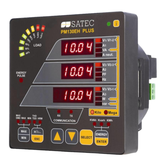
A N D C O N T R O L S Chapter 3 Using Front Display This chapter provides PM130 PLUS Power meter series front panel information and operating procedures. Figure 3 -1: PM130 PLUS Unit 3.1 Indicators and Controls... -
Page 47: Load Bar Graph
Configuring the Display). Display Features Measurement Units The PM130 PLUS has a selectable resolution for volts, amps and powers presented on the front display and via communications. See Device Options in Chapter 5 for information on selecting the data resolution in the PM130 PLUS. - Page 48 If no buttons are pressed for 30 seconds while in the common measurements display, and the Auto Scroll option is enabled in the meter, the display automatically scrolls through all available pages. The scroll interval can be adjusted through the display setup (see Configuring the Display). PM130 PLUS Powermeter Series...
-
Page 49: Navigation Buttons
Total and phase energies: select a total energy, or a phase energy page from the Energy Display. While holding the SELECT button down, press and hold the ENTER button for about 5 seconds. The displayed data is reset to zero. PM130 PLUS Powermeter Series... -
Page 50: Common Measurements Display
Fundamental phase L1 powers (PM130EH, if enabled) kW/MW H1.L2 Fundamental phase L2 powers (PM130EH, if enabled) kW/MW H1.L3 Fundamental phase L3 powers (PM130EH, if enabled) kW/MW U.Unb V% unb Voltage unbalance, percent C.Unb I% unb Current unbalance, percent PM130 PLUS Powermeter Series... -
Page 51: Min/Max And Maximum Demand Display
Minimum total var V1/V12 Minimum volts V2/V23 V3/V31 Maximum amps kVA/MVA Maximum total VA Maximum total PF (absolute) kW/MW Maximum total W Maximum neutral current Maximum frequency kvar/Mvar Maximum total var V1/V12 Maximum volt demands V2/V23 PM130 PLUS Powermeter Series... -
Page 52: Harmonics Display (Pm130Eh)
I3 TDD I1 K-Factor Current K-Factor I2 K-Factor I3 K-Factor Table 8: Individual Voltage Harmonics V1/V12 HD% Order 3 harmonic distortion V2/V23 HD% V3/V31 HD% V1/V12 HD% Order 5 harmonic distortion V2/V23 HD% V3/V31 HD% … PM130 PLUS Powermeter Series... -
Page 53: Energy Display (Pm130E/Eh)
56789 Ac.E Total kWh export 1234 56789 rE.E Total kvarh export 1234 56789 Ac.i 1 Phase L1 kWh import 1234 56789 rE.i 1 Phase L1 kvarh import 1234 56789 AP. 1 Phase L1 kVAh 1234 56789 PM130 PLUS Powermeter Series... -
Page 54: Status Display
1234 56789 … r4.t8 Tariff 8 reading 1234 56789 3.3 Status Display The meter has a separate status information display accessible through the primary meter menu. See Using the Menus for information on navigating in menus. PM130 PLUS Powermeter Series... - Page 55 Counter #2 value (a time counter – in <hour> 0.1 hour units) 12345 Cnt.3 Counter #3 value (a time counter – in <hour> 0.1 hour units) 12345 Cnt.4 Counter #4 value (a time counter – in <hour> 0.1 hour units) 12345 PM130 PLUS Powermeter Series...
-
Page 56: Pulse And Time Counters
5 seconds until the alarm code is reset to none. Diagnostics Display The diagnostics display shows a list of the device diagnostic codes recorded as a result of the meter self-test diagnostics during start-up and PM130 PLUS Powermeter Series... -
Page 57: Using The Menus
5 seconds until the diagnostic message is reset to none. 3.4 Using the Menus Navigation Buttons The PM130 PLUS has a menu-driven setup. Press and release the SELECT button to access the meter menus. See the following table for button operations in menus. -
Page 58: Entering The Password
Adjust the remaining digits in the same manner. Press ENTER to confirm the password. If the password you entered is correct, you are moved to the Main menu, otherwise you return back to the primary menu. PM130 PLUS Powermeter Series... -
Page 59: Selecting A Menu Entry
Scroll through the parameter list with the UP or DOWN arrow buttons until the required parameter name appears. To change the selected parameter: Press the SELECT button to highlight the lower item. Figure 3 -6: Changing a Parameter PM130 PLUS Powermeter Series... - Page 60 Press the ENTER button to store your selection or press the ESC button to leave the parameter unchanged. You return to the middle window and can continue scrolling through the remaining parameters or return to the main menu. Press ESC to exit the menu. PM130 PLUS Powermeter Series...
-
Page 61: Chapter 4 Using Pas Software
PM130 PLUS features, monitor your meters on-line, retrieve recorded files and view reports. PAS can communicate with your PM130 PLUS via a serial port and via the Ethernet. This chapter gives information on how to install and run PAS on your computer, and how to prepare information for your meter using PAS. - Page 62 Type a site name for your device in the File name box, click New, and then click OK. On the Instrument Setup tab, select PM130 PLUS in the Model box. PAS automatically selects the appropriate instrument options for your meter.
-
Page 63: Setting Up Communications
C O M M U N I C A T I O N S 4.3 Setting up Communications You can communicate with the PM130 PLUS via a PC RS-232 serial port or through the Internet. To configure communications with the PM130 PLUS:... -
Page 64: Communicating Through The Internet
DNP3/TCP connections on port 20000. The host port is set automatically as you select the protocol. Select Modbus RTU/TCP for Modbus/TCP or DNP3 for DNP3/TCP. In the Wait for answer box, adjust the time that PAS waits for a connection before announcing an error. PM130 PLUS Powermeter Series... -
Page 65: Setting Up The Meter
Select the target database from the file pane. Click OK. You can also reuse a setup from another site by copying it to your present site database. To copy a setup from another site’s database: Click Open. Select the desired source site database. PM130 PLUS Powermeter Series... -
Page 66: Downloading Setups To The Meter
Click Receive if you wish to retrieve the meter setup once again. To store the setup to the meter site database, click Save As, and then click OK. Batch Upload To upload all setups from the device to the site database at once: PM130 PLUS Powermeter Series... -
Page 67: Authorization
OK. If your authorization was successful, you are not prompted for the password again until you close the dialog box. Configuring Meter Security in Chapter 5 for more information on the meter password security. PM130 PLUS Powermeter Series... -
Page 68: Chapter 5 Configuring The Pm130 Plus
Select Communications Setup from the Meter Setup menu, and then click on the Serial Ports Setup tab. In the Port box, select the desired device port. Figure 5 -1: Communication Setup Dialog Box – Serial Ports Setup Tab PM130 PLUS Powermeter Series... -
Page 69: Setting Up Ethernet
Ethernet module is plugged into the meter. It allows you to set up the meter network address and the default gateway. Viewing and Changing Setup Options in Chapter 3 for information on configuring parameters via the front display. PM130 PLUS Powermeter Series... - Page 70 The table below lists available network options. Table 15: Ethernet Setup Options Display Label Parameter Options Default Device IP Address 192.168.0.203 Network Subnet Mask 255.255.255.0 Network Default Gateway 192.168.0.1 TCP Service Port 502 = Modbus/TCP 20000 = DNP3/TCP PM130 PLUS Powermeter Series...
-
Page 71: Setting Up Gprs Network
You may need to wait some additional time until PAS restores a connection with your device. Setting Up GPRS Network The PM130 PLUS can provide wireless GPRS communications with the remote Modbus/TCP server via GPRS modem module. See Connecting a... -
Page 72: Setting Up Expertpower Client
Device Control dialog in PAS (see Viewing Communication Status and Statistics). Setting Up eXpertPower Client The PM130 PLUS has an embedded eXpertPower client that provides communications with the eXpertPower server – the SATEC proprietary Internet services. Connections to the eXpertPower server are handled on a periodic basis. -
Page 73: Setting Up Tcp Notification Client
Modbus/TCP server and send notification messages either on events, or periodically on a time basis. To set up communications with a remote TCP Notification server, select Communication Setup from the Meter Setup menu, and then click on the TCP Notification Client Setup tab. PM130 PLUS Powermeter Series... - Page 74 "Notification" action setpoint action list (see Configuring Alarm/Control Setpoints). See the PM130 PLUS Modbus Reference guide for more information on operation of the notification client and the notification message structure. PM130 PLUS Powermeter Series...
-
Page 75: General Meter Setup
S E T U P 5.2 General Meter Setup Basic Meter Setup This section describes how to configure the PM130 PLUS for your particular environment and application. Before operating your meter, provide the device with basic information about your electrical network. - Page 76 4-wire Wye using 3 PTs (3 element), line-to-neutral voltage readings 3DIR2 3-wire Delta Direct Connection using 2 CTs (2 element) 4LL3 4-wire Wye using 3 PTs (3 element), line-to-line voltage readings 3OP3 3-wire Open Delta using 3 CTs (2½ element) PM130 PLUS Powermeter Series...
-
Page 77: Device Options
Calculation tESt Energy Test Mode OFF = disabled Disabled Setting this option puts the E, EH Ac.Ei = Wh pulses meter into the energy test mode rE.Ei = varh pulses (see Energy Pulse LED Chapter 3) PM130 PLUS Powermeter Series... - Page 78 This mode is recommended for electrical networks with low harmonic distortion, commonly with THD < 5% for volts, and THD < 10% for PM130 PLUS Powermeter Series...
-
Page 79: Configuring Digital Inputs
Configuring Digital Inputs The PM130 PLUS can be provided with four, eight or twelve digital inputs that can be linked to control setpoints to give an indication on input status change (see Configuring Alarm/Control Setpoints), or can be linked to... - Page 80 The debounce time is applied the same for all digital inputs. If you change the debounce time for a digital input, the same debounce time is automatically assigned to the others. PM130 PLUS Powermeter Series...
-
Page 81: Configuring Relay Outputs
General M E T E R S E T U P Configuring Relay Outputs The PM130 PLUS can be provided with two optional relay outputs. Each relay can be operated either locally from the alarm/control setpoints in response event remote... - Page 82 InS = INVERTING energized in its active (operated) state. (N.C.) Inverting polarity: the relay is normally energized in its non-active state and is de- energized in its active (operated) state. It is called failsafe relay operation. PM130 PLUS Powermeter Series...
-
Page 83: Configuring Analog Outputs
To store your new settings: Press the ENTER button when the middle window is highlighted. You are returned to the upper window and can select another analog output or exit the menu. Press ESC to exit the menu. PM130 PLUS Powermeter Series... - Page 84 (1 or 20 mA) When you select an output parameter for the analog output channel, the default engineering scales are set automatically. They correspond to the maximum available scales. If the parameter actually covers a lower range, PM130 PLUS Powermeter Series...
-
Page 85: Configuring Counters
0 to 120V, set the 1 mA scale to 60V; then the 120V reading will be scaled to 2 mA. Configuring Counters The PM130 PLUS has four six-digit general counters that can count pulses delivered through the device digital inputs with a programmable scale PM130 PLUS Powermeter Series... - Page 86 Links a digital input to the DIGITAL INPUT counter #1 - #12 SCAL Multiplier 1-9999 The value added to the counter when a pulse is detected on the pulse source input Counter Value Displays the present counter contents PM130 PLUS Powermeter Series...
-
Page 87: Configuring Alarm/Control Setpoints
Type in the required value into the Counter Value field. Click Send. Configuring Alarm/Control Setpoints The PM130 PLUS has an embedded logical controller that can perform different actions in response to user-defined internal and external events. Unlike a PLC, the meter uses a simplified programming technique based on setpoints that allows the user to define a logical expression based on measured analog and digital values that produce a required action. - Page 88 Not applicable for digital triggers. Release limit The threshold (in primary units) at which the conditional expression would be evaluated to false. Defines the hysteresis for analog triggers. Not applicable for digital triggers. PM130 PLUS Powermeter Series...
- Page 89 Binary (digital) triggers like digital inputs and relays are tested for ON/CLOSED or OFF/OPEN status. In the PM130, the binary events are level-sensitive events. An event is asserted all the time while the corresponding condition exists. PM130 PLUS Powermeter Series...
-
Page 90: Configuring The Display
Using the Front Display Select the diSP entry from the main menu. See Viewing and Changing Setup Options in Chapter 3 for information on configuring parameters via the front display. See Table 27 for the available options. PM130 PLUS Powermeter Series... -
Page 91: Local Time Settings
Select rtc from the main menu. See Viewing and Changing Setup Options in Chapter 3 for information on configuring parameters via the front display. Using PAS Select General Setup from the Meter Setup menu, and then click on the Local Settings tab. PM130 PLUS Powermeter Series... - Page 92 DST End Hour The hour when Daylight Hour Saving Time ends. SYnC Time None None The external port receiving Synchronization di.1 = DI1 the time synchronization di.2 = DI2 Input pulses di.3 = DI3 di.4 = DI4 PM130 PLUS Powermeter Series...
-
Page 93: Configuring Meter Security
ON enables password protection and OFF disables password protection. Press ENTER to confirm your new setting, or ESC to discard changes. Press ESC to exit the menu. When password protection is enabled, you are not able to change device settings through display PM130 PLUS Powermeter Series... - Page 94 Figure 5 -14: Password Setup Dialog Box To change the password: Type in a new 4-digit password Repeat the password in the Confirm new password box Check Enable password protection to enable password checking Click Send. PM130 PLUS Powermeter Series...
-
Page 95: Configuring Billing/Tou
Configure the daily tariff schedule using the TOU daily profiles for all types of days and seasons. Configure the season tariff schedule using the TOU calendar. Configuring Billing/Tariff Registers To configure the billing/TOU registers in your meter: Select Energy/TOU from the Meter Setup menu. PM130 PLUS Powermeter Series... - Page 96 DI1-DI4 Multiplier 0.001 to 100.000 1.000 The multiplication factor for the energy source. Unchangeable for internal energy sources. Target Reg#1- Reg#4 None Defines the target billing register for the energy source. It is set automatically. PM130 PLUS Powermeter Series...
-
Page 97: Configuring The Daily Tariff Schedule
TOU daily profiles. Configuring the Season Tariff Schedule To configure your season tariff schedule, select Energy/TOU from the Meter Setup menu, and then click on the TOU Calendar tab. PM130 PLUS Powermeter Series... - Page 98 The above picture shows a typical single-season tariff schedule with two daily tariff profiles configured for working days, and weekends and the designated U.S.A. holidays. PM130 PLUS Powermeter Series...
-
Page 99: Configuring Recorders
The size of the file record for a single channel or a single section. It is set automatically depending on the file and on the number of parameters in the data records Parameters The number of parameters in a single data log record PM130 PLUS Powermeter Series... - Page 100 Events Event log 3200 200 last events Data log #1 46080 5760 5760 15-min data profile for 15 days 17 Data log #16 8640 Daily billing/TOU profile for 90 days, 4 registers, totals + 3 tariffs PM130 PLUS Powermeter Series...
-
Page 101: Configuring The Event Recorder
To create a new data log file or re-configure an existing file: Double click on the file partition with the left mouse button. Select a partition type for your file. PM130 PLUS Powermeter Series... - Page 102 The file is organized as a multi-section file that has a separate section of the same structure for each billing energy and maximum demand register. The number of sections is taken automatically from the Billing/TOU Registers setup (see Configuring Billing/Tariff Registers). If the maximum demand PM130 PLUS Powermeter Series...
- Page 103 Periodic recording data is triggered by Setpoint #1 that is linked to the meter clock. To change the periodic rate at which data is recorded, change the time interval for the MINUTE INTERVAL trigger in Setpoint #1 (see Configuring Alarm/Control Setpoints). PM130 PLUS Powermeter Series...
- Page 104 Data log #16 is pre-configured for daily billing energy and maximum demand recording for the last 90 days. It is automatically updated once a day. Billing Profile Log File in Appendix E for the file record structure. PM130 PLUS Powermeter Series...
-
Page 105: Configuring Communication Protocols
Configuring Modbus Modbus Point Mapping The PM130 PLUS provides 120 user assignable registers at addresses 0 to 119. You can re-map any register available in the meter to any assignable register so that registers found at different locations may be accessed with a single request by re-mapping them to adjacent addresses. -
Page 106: Configuring Dnp3
Table 30: DNP Options Parameter Options Default Description Binary Inputs (BI) Binary Input Object Single-bit Single-bit The default BI object variation for With Status requests with qualifier code 06 when no specific variation is requested Analog Inputs (AI) PM130 PLUS Powermeter Series... - Page 107 Time Sync Period elapses. The master should synchronize the time in the meter by sending the Time and Date object to clear this bit. The meter does not send time synchronization requests if the Time Sync Period is set to 0. PM130 PLUS Powermeter Series...
- Page 108 Class 0 response. Click Send to download your setup to the meter. The factory-set Class 0 point ranges are shown in the picture below. Figure 5 -22: Protocol Setup Dialog Box – DNP Class 0 Points Tab PM130 PLUS Powermeter Series...
-
Page 109: Chapter 6 Device Control And Upgrading
Clears Min/Max log Clears all counters Cnt1 – Cnt4 Clears counter #1-#4 diAG Clears device diagnostics Using PAS Ensure that the On-line button on the PAS toolbar is checked, and then select Reset from the Monitor menu. PM130 PLUS Powermeter Series... -
Page 110: Updating The Meter Clock
Check the corresponding boxes, and then click OK. Figure 6 -2: Reset Maximum Demands Dialog Box 6.2 Updating the Meter Clock Using the Front Display Select the rtc entry from the main menu. PM130 PLUS Powermeter Series... - Page 111 PAS toolbar. The RTC dialog box displays the current PC time and the time in your meter. Figure 6 -3: Real Time Clock Window To synchronize the meter clock with the PC clock, click Set. PM130 PLUS Powermeter Series...
-
Page 112: Viewing And Clearing Device Diagnostics
To clear the device diagnostics events, click on Clear. 6.4 Viewing Communication Status and Statistics Ensure that the On-line button on the PAS toolbar is checked, select Device Control from the Monitor menu, and then click on the Communications tab. PM130 PLUS Powermeter Series... -
Page 113: Remote Relay Control
To access the relay control dialog, ensure that the On-line button on the PAS toolbar is checked, select Device Control from the Monitor menu, and then click on the Remote Relay Control tab. PM130 PLUS Powermeter Series... -
Page 114: Upgrading Device Firmware
Ensure that the On-line button on the PAS toolbar is checked, and then select Flash Downloader from the Monitor menu and confirm downloading. Point to the firmware upgrade file for your meter, click Open, and then confirm upgrading the meter. PM130 PLUS Powermeter Series... - Page 115 115,200 bps to download the file to the meter. After upgrading firmware is completed, the meter restarts, so communications can be temporarily lost. You may need to wait a short duration until PAS restores a connection with your device. PM130 PLUS Powermeter Series...
-
Page 116: Chapter 7 Monitoring Meters
You can view acquired data in a tabular form or in a graphical form as a data trend. PM130 PLUS Powermeter Series... - Page 117 PAS supports 33 programmable data sets with up to 40 data parameters. Set #0 is intended for simple meters, which have a limited number of parameters, and is not recommended for the use with the PM130 PLUS. To re-organize data sets, select RT Data Sets from the Monitor menu or click on the button on the local toolbar.
-
Page 118: Viewing Real-Time Min/Max Log
Select the device site from the list box on the PAS toolbar. Point to RT Min/Max Log on the Monitor menu, and then select a data set you want to view. Ensure that the On-line button on the PAS toolbar is checked. Click on the Poll button PM130 PLUS Powermeter Series... -
Page 119: Viewing Real-Time Waveforms
When you open a new file, PAS shows you a waveform graph with non- overlapped waveforms as shown in the picture above. Click on the button on the local toolbar to see overlapped waveforms. Click on the button for non-overlapped waveforms. PM130 PLUS Powermeter Series... - Page 120 To enable or disable the symmetrical components, click on the waveform window with the right mouse button, select Options..., check or uncheck PM130 PLUS Powermeter Series...
-
Page 121: Viewing Real-Time Harmonic Spectrum
Harmonics can be displayed as a spectrum chart for a selected channel or in a table. PAS can also synthesize waveforms based on the harmonic spectrum to let you view a shape of the voltage and current waveforms in your network. PM130 PLUS Powermeter Series... - Page 122 To change a phase, click on the window with the right mouse button, select Options..., check the phase you want displayed, and then click OK. PM130 PLUS Powermeter Series...
- Page 123 To select the channels you want to view, click with the right mouse button on the waveform window, select “Channels...”, check the channels for the phase you want displayed, and then click OK. PM130 PLUS Powermeter Series...
- Page 124 M E T E R S R E A L - T I M E H A R M O N I C S P E C T R U M Figure 7 -6: RT Harmonic Monitor – Synthesized Waveforms PM130 PLUS Powermeter Series...
-
Page 125: Chapter 8 Retrieving And Storing Files
If you wish to retrieve data starting with a known date, check the “From” box and select the start date for retrieving data. If you wish to retrieve data recorded before a known date, check the “To” box and select the last date for retrieving data. Click OK. PM130 PLUS Powermeter Series... -
Page 126: Using The Upload Scheduler
Click Browse and select a database for storing retrieved data, or type the name for a new database, select a directory where you want to save it, and then click OK. Click Configure or double click on the site row. PM130 PLUS Powermeter Series... - Page 127 When the Upload Scheduler fails to retrieve data from the device, or some data is missing, or another problem occurs, it puts an error message to the log file. To review this file, select System Log from the View menu. PM130 PLUS Powermeter Series...
-
Page 128: Viewing Files On-Line
To manually convert your waveforms or a data log into COMTRADE or PQDIF format: Click on the Export button on the PAS toolbar. Select the database and a data log table you want to export, and then click Open. PM130 PLUS Powermeter Series... - Page 129 Select a folder where you want to store converted files, type in the converted file’s name, select a desired output file format, and then click on Save. Repeat the same for all tables you wish to be converted. Click OK. PM130 PLUS Powermeter Series...
-
Page 130: Exporting Files In Excel Format
Check the Enable box and select a periodic schedule for archiving your files for this site. Click OK. To avoid archiving partially updated data, archiving is performed in a day after expiring a scheduled period and not before 2 hours a.m. PM130 PLUS Powermeter Series... -
Page 131: Chapter 9 Viewing Files
If you have an application that does not support this format, you may instruct PAS to drop milliseconds. To change the way PAS records and displays the timestamp: Select Options from the Tools menu and click on the Preferences tab. Select the preferred timestamp format. PM130 PLUS Powermeter Series... -
Page 132: Working With Tables
OK. Checkboxes for channels that are not available in the present view are dimmed. Selecting Primary and Secondary Units Voltages and currents can be displayed in primary or secondary units. PM130 PLUS Powermeter Series... - Page 133 To disable delta measurements, click on the Delta button once again. Using a Zoom You can use a horizontal and, for waveforms, also a vertical, zoom to change size of your graph. PM130 PLUS Powermeter Series...
-
Page 134: Viewing The Event Log
The Event log is displayed in a tabular view, one event per row. Use the scroll bar to view the entire log contents. Figure 9 -1: Event Log Window Working with Tables for more information on viewing options. PM130 PLUS Powermeter Series... -
Page 135: Viewing The Data Log
To view data in a graphical form, click on the Data Trend button on the local toolbar. To change the time range for your graph, click on the Time Range button on the local toolbar, and then select the desired date and time range. PM130 PLUS Powermeter Series... -
Page 136: Appendix A Technical Specifications
Input to ground: 2500 VAC 12 VDC Option: Rated input: 9.5-18 VDC, Burden 4VA Isolation: 1500VDC 24/48 VDC Option: Rated input: 18.5-58 VDC, Burden 4VA Isolation: 1500VDC Wire size: up to 12 AWG (up to 3.5 mm2) PM130 PLUS Powermeter Series... - Page 137 A ppendix A Technical Specifications Input Ratings Voltage Inputs – Installation category III Measurement operating range: 690VAC line-to-line, 400VAC line-to-neutral Direct input and input via PT (up to 828VAC line-to-line, up to 480VAC line-to- neutral) Input impedance: 1000 k Burden for 400V: <...
- Page 138 Isolation: 2500 VAC 1 min Power supply: internal Accuracy: 0.5% FS Update time: 1 cycle Connector type: removable, 5 pins. Wire size: 14 AWG (up to 1.5 mm2) Communication Ports COM1 RS-485 optically isolated port Isolation: 3000 VAC 1 min PM130 PLUS Powermeter Series...
- Page 139 A ppendix A Technical Specifications Baud rate: up to 115.2 kbps. Supported protocols: Modbus RTU, DNP3, and SATEC ASCII. Connector type: removable, 3 pins. Wire size: up to 14 AWG (up to 1.5 mm2). COM2 (Optional module) Ethernet Port Transformer-isolated 10/100BaseT Ethernet port.
- Page 140 Comply with IEC 61000-6-4: Radiated/Conducted class A Comply with IEC CISPR 22: Radiated/Conducted class A Safety/Construction: UL File no. E236895 Meets IEC 61010-1: 2006 AC and Impulse Insulation: Comply with IEC 62052-11: 2500 VAC during 1 minute 6KV/500Ω @ 1.2/50 μs impulse PM130 PLUS Powermeter Series...
- Page 141 A ppendix A Technical Specifications A.12 Measurement Specifications Table 33: Measurement Specifications Parameters Parameter Full Scale @ Input Accuracy Range Range % FS Conditions Reading Voltage 120VxPT @ 120V 0.02 10% to 120% FS 0 to 1,150,000 V 400VxPT @ 690V Starting voltage 1.5-5.0% FS (selectable) Line current...
- Page 142 A ppendix A Technical Specifications Measurement error is typically less than the maximum error indicated. PM130 PLUS Powermeter Series...
-
Page 143: Appendix B Analog Output Parameters
PF LEAD AVR Total PF Lead 1-Sec Auxiliary Values A.nEU.C In AVR In Current Ar. Fr FREQ AVR Frequency E, EH Demands Acd.P.i kW IMP ACD Accumulated kW import demand Acd.P.E kW EXP ACD Accumulated kW export demand PM130 PLUS Powermeter Series... - Page 144 EXP ACD Accumulated kvar export demand Acd.S kVA ACD Accumulated kVA demand In 4LN3, 3LN3 and 3BLN3 wiring modes, the voltages will be line-to- neutral; for any other wiring mode, they will be line-to-line voltages. PM130 PLUS Powermeter Series...
-
Page 145: Appendix C Setpoint Triggers And Actions
1-Sec Values on any Phase A.Hi. U High voltage HI VOLT AVR A.Lo. U Low voltage LO VOLT AVR A.Hi. C HI AMPS AVR High current A.Lo. C LO AMPS AVR Low current 1-Sec Total Values PM130 PLUS Powermeter Series... - Page 146 Operate relay RO1 r2 On OPERATE RELAY #2 Operate relay RO2 r1 OFF RELEASE RELAY #1 Release latched relay RO1 r2 OFF RELEASE RELAY #2 Release latched relay RO2 In.Cn.1 INC CNT #1 Increment counter #1 PM130 PLUS Powermeter Series...
- Page 147 TIME CNT #3 Count operation time using counter #3 ti.Cn.4 TIME CNT #4 Count operation time using counter #4 notiF NOTIFICATION Send a notification message dLoG1 DATA LOG #1 Record data to Data Log #1 PM130 PLUS Powermeter Series...
-
Page 148: Appendix D Parameters For Data Monitoring And Logging
I2 THD I2 Current THD I3 THD I3 Current THD I1 KF I1 K-Factor I2 KF I2 K-Factor I3 KF I3 K-Factor I1 TDD I1 Current TDD I2 TDD I2 Current TDD I3 TDD I3 Current TDD PM130 PLUS Powermeter Series... - Page 149 V2 THD V2/V23 Voltage THD V3 THD V3/V31 Voltage THD I1 THD I1 Current THD I2 THD I2 Current THD I3 THD I3 Current THD I1 KF I1 K-Factor I2 KF I2 K-Factor I3 KF I3 K-Factor PM130 PLUS Powermeter Series...
- Page 150 I3 Ampere demand kW IMP BD kW import block demand kvar IMP BD kvar import block demand kVA BD kVA block demand kW IMP SD kW import sliding window demand kvar IMP SD kvar import sliding window demand PM130 PLUS Powermeter Series...
- Page 151 L1 kWh IMP L2 kWh import L2 kWh IMP L3 kWh import L3 kvarh IMP L1 kvarh import L1 kvarh IMP L2 kvarh import L2 kvarh IMP L3 kvarh import L3 kVAh L1 kVAh total L1 PM130 PLUS Powermeter Series...
- Page 152 V3 H01 ANG H01 Harmonic angle V3 H02 ANG H02 Harmonic angle … V3 H40 ANG H40 Harmonic angle ANG I1 I1 Harmonic Angles I1 H01 ANG H01 Harmonic angle I1 H02 ANG H02 Harmonic angle PM130 PLUS Powermeter Series...
- Page 153 I3 MIN I3 Current MIN TOTAL Minimum 1-Cycle Total Values kW MIN Total kW kvar MIN Total kvar kVA MIN Total kVA PF MIN Total PF MIN AUX Minimum 1-Cycle Auxiliary Values In MIN In Current PM130 PLUS Powermeter Series...
- Page 154 REG1 TRF1 Tariff #1 register REG1 TRF2 Tariff #2 register … … REG1 TRF8 Tariff #8 register TOU REG2 E, EH Billing TOU Energy Register #2 REG2 TRF1 Tariff #1 register REG2 TRF2 Tariff #2 register PM130 PLUS Powermeter Series...
- Page 155 Long Data Name Description Name kW IMP ACD kW IMP ACC DMD Accumulated demand kW IMP PRD kW IMP PRD DMD Predicted sliding window demand PF IMP@kVA MD PF IMP@kVA MXDMD PF (import) at maximum kVA demand PM130 PLUS Powermeter Series...
- Page 156 TOU REG1 TRF1 Billing tariff energy register REG1 TRF1 MD DMD1 TRF1 MAX Billing tariff register maximum demand TRF1 SEASON TRF1 Generic billing tariff energy register TRF1 MD SEASON TRF1 Generic billing tariff register maximum demand PM130 PLUS Powermeter Series...
-
Page 157: Appendix E Billing/Tou Profile Log File
Tariff #3 max. demand reading TRF4 MD Tariff #4 max. demand reading TRF5 MD Tariff #5 max. demand reading TRF6 MD Tariff #6 max. demand reading TRF7 MD Tariff #7 max. demand reading TRF8 MD Tariff #8 max. demand reading PM130 PLUS Powermeter Series... - Page 158 P R O F I L E L O G F I L E The number of parameters in each section is automatically configured depending on the number of actual tariffs you defined in the TOU Daily Profiles. PM130 PLUS Powermeter Series...
-
Page 159: Appendix F Data Scales
Appendix F Data Scales The maximum values for volts, amps and power in the PM130 PLUS setup and in communications are limited by the voltage and current scale settings. See Device Options in Chapter 4 on how to change the voltage and current scales in your meter. -
Page 160: Appendix G Device Diagnostic Codes
The clock time has been lost Lo.bAt Low battery (with a Battery replacement is battery backup unit) required EEPr EEPROM fault Hardware failure Diagnostics Display in Chapter 3 for more information on the PM130 PLUS built-in diagnostics. PM130 PLUS Powermeter Series... -
Page 161: Index
Total Demand Distortion, 138 70, 110 Total Harmonic Distortion, 138 TOU, 93 TOU module, 15, 36 High Resolution Option, 46 Wiring Mode, 6, 27, 28, 29, 30, 73, 74 inputs, 18 Wye, 26, 27, 28, 29, 74, 75 PM130 PLUS Powermeter Series...
Need help?
Do you have a question about the PM130 PLUS and is the answer not in the manual?
Questions and answers