HPE ProLiant DL385 Gen10 Maintenance And Service Manual
Hide thumbs
Also See for ProLiant DL385 Gen10:
- User manual (177 pages) ,
- User manual (170 pages) ,
- Maintenance and service manual (166 pages)
Table of Contents
Advertisement
Quick Links
Download this manual
See also:
User Manual
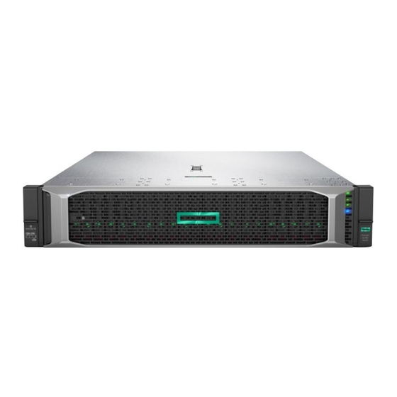
HPE ProLiant DL385 Gen10 Server
Maintenance and Service Guide
Abstract
This document is for the person who installs, administers, and troubleshoots servers and storage
systems. Hewlett Packard Enterprise assumes you are qualified in the servicing of computer
equipment and trained in recognizing hazards in products with hazardous energy levels.
Part Number: 880927-001
Published: November 2017
Edition: 1
Advertisement
Table of Contents

Related Manuals for HPE ProLiant DL385 Gen10


Summary of Contents for HPE ProLiant DL385 Gen10
- Page 1 HPE ProLiant DL385 Gen10 Server Maintenance and Service Guide Abstract This document is for the person who installs, administers, and troubleshoots servers and storage systems. Hewlett Packard Enterprise assumes you are qualified in the servicing of computer equipment and trained in recognizing hazards in products with hazardous energy levels.
- Page 2 © Copyright 2017 Hewlett Packard Enterprise Development LP Notices The information contained herein is subject to change without notice. The only warranties for Hewlett Packard Enterprise products and services are set forth in the express warranty statements accompanying such products and services. Nothing herein should be construed as constituting an additional warranty. Hewlett Packard Enterprise shall not be liable for technical or editorial errors or omissions contained herein.
-
Page 3: Table Of Contents
Chassis Intrusion Detection Switch spare part............... 21 Rear serial port interface spare part..................21 GPU option spare part......................21 HPE 12Gb DL38x Gen10 SAS Expander Card spare part.............21 HPE Smart Storage Battery spare parts.................21 Power module spare part......................22 LFF I/O UID spare parts......................22 HPE Trusted Platform Module 2.0 spare part.................22... - Page 4 Removing and replacing a GPU enablement board................76 Removing and replacing a DIMM...................... 77 Removing and replacing a processor....................78 Removing and replacing the HPE Smart Storage Battery..............81 Removing and replacing a type -a Smart Array Controller..............82 Removing and replacing the system battery..................83 Removing and replacing the system board..................
- Page 5 HPE ProLiant Gen10 DL Servers Storage Cabling Guidelines............89 Cabling diagrams..........................89 Cable routing: Front 2SFF SAS side by side for LFF............. 92 Cable routing: Front 2SFF drive option for SFF..............93 Cable routing: Front 2SFF drive option for LFF..............93 Cable routing: Front/rear 2Premium SAS (SFF + LFF)............94 Cable routing: Front 8SFF SAS/SATA drive options...............95...
- Page 6 Mechanical specifications........................140 Power supply specifications......................141 HPE 500W Flex Slot Platinum Hot Plug Low Halogen Power Supply........142 HPE 800W Flex Slot Platinum Hot Plug Low Halogen Power Supply........143 HPE 800W Flex Slot Titanium Hot Plug Low Halogen Power Supply........143 HPE 800W Flex Slot Universal Hot Plug Low Halogen Power Supply.........
-
Page 7: Illustrated Parts Catalog
Illustrated parts catalog Mechanical components Hewlett Packard Enterprise continually improves and changes product parts. For complete and current supported parts information, see the Hewlett Packard Enterprise PartSurfer website (http://www.hpe.com/ info/partssurfer). Item Description Air baffle spare part on page 7 Access panel spare parts on page 8... -
Page 8: Access Panel Spare Parts
Description Spare part number Air baffle P00659-001 Access panel spare parts Customer self repair on page 24: mandatory Description Spare part number Access panel (SFF model) P00660-001 Access panel (LFF model) P00661-001 Tertiary PCI riser cage spare part Customer self repair on page 24: optional Description Spare part number Tertiary PCI riser cage... -
Page 9: Rail Kit Spare Parts
Rail kit spare parts Customer self repair on page 24: mandatory Description Spare part number SFF 2U easy install rail kit 744114-001 LFF 2U easy install rail kit 744115-001 2U cable management arm for easy install rail kit 744116-001 SFF 2U BB rail kit 662535-001 LFF 2U BB rail kit 692480-001... -
Page 10: System Components
707300-001 System components Hewlett Packard Enterprise continually improves and changes product parts. For complete and current supported parts information, see the Hewlett Packard Enterprise PartSurfer website (http://www.hpe.com/ info/partssurfer). Fan blank, Smart Storage Battery latch, and PCIe retainer kit spare parts... -
Page 11: Dimm Spare Parts
Item Description DIMM spare parts on page 11 Processor spare parts on page 12 Heatsink spare parts on page 12 Power supply spare parts on page 12 Controller spare parts on page 13 PCI riser board spare parts on page 14 Ethernet adapter spare parts on page 14 FlexibleLOM adapter spare parts on page 14 System board spare part on page 15... -
Page 12: Processor Spare Parts
Customer self repair on page 24: mandatory Description Spare part number HPE 800W Flex Slot Universal Hot-Plug Low 866727-001 Halogen Power Supply HPE 800W Flex Slot -48VDC Hot-Plug Low Halogen 866728-001 Power Supply HPE 500W Flex Slot Platinum Hot-plug Low Halogen 866729-001 Power Supply... -
Page 13: Controller Spare Parts
Description Spare part number HPE 800W Flex Slot Titanium Hot-Plug Low Halogen 866793-001 Power Supply HPE 1600W Flex Slot Platinum Hot-Plug Low 863373-001 Halogen Power Supply Controller spare parts Smart Array controller spare parts Customer self repair on page 24: mandatory... -
Page 14: Pci Riser Board Spare Parts
Description Spare part number HPE StoreFabric CN1200E 10Gb Converged 767078-001 Network Adapter HPE StoreFabric CN1200E-T 10Gb Converged 827607-001 Network Adapter PCI riser board spare parts Customer self repair on page 24: optional Description Spare part number 2x8 x16 PCIe M.2 riser... -
Page 15: System Board Spare Part
Customer self repair on page 24: mandatory Description Spare part number System battery 319603-001 Server options Hewlett Packard Enterprise continually improves and changes product parts. For complete and current supported parts information, see the Hewlett Packard Enterprise PartSurfer website (http://www.hpe.com/ info/partssurfer). System board spare part... -
Page 16: Drive Spare Parts
GPU option spare part on page 21 HPE 12Gb DL38x Gen10 SAS Expander Card spare part on page 21 HPE Smart Storage Battery spare parts on page Power module spare part on page 22 LFF I/O UID spare parts on page 22 HPE Trusted Platform Module 2.0 spare part on... - Page 17 Hot-plug drive spare parts Customer self repair on page 24: mandatory Description Spare part number 1 TB SAS 7.2K SFF SC DS HDD 832984-001 1 TB SAS 7.2K SFF SC 512e DS HDD 765872-001 1 TB SATA 7.2K LFF SC DS HDD 862128-001 1 TB SAS 7.2K LFF SC DS HDD 846612-001...
- Page 18 Description Spare part number 300 GB SAS 15K SFF SC DS HDD 870792-001 600 GB SAS 15K SFF SC DS HDD 870794-001 600 GB SAS 15K SFF SC 512e DS HDD 870797-001 900 GB SAS 15K SFF SC DS HDD 870795-001 900 GB SAS 15K SFF SC 512e DS HDD 870798-001...
- Page 19 Description Spare part number 800 GB SAS 12G WI SFF SC DS SSD 873564-001 800 GB SAS 12G MU SFF SC DS SSD 873569-001 960 GB SAS RI SFF SC DS SSD 875682-001 960 GB SAS RI SFF SC DS SSD 872432-001 1.6 TB SAS 12G MU SFF SC DS SSD 873570-001...
-
Page 20: Fan Spare Part
Description Spare part number 960GB SATA MU LFF SCC DS SSD 879017-001 960GB SATA RI SFF SC DS SSD 878849-001 960GB SATA 6G RI SFF SC DS SSD 868928-001 960GB SATA 6G MU SFF SC DS SSD 872520-001 960GB SATA 6G MU LFF SCC DS SSD 872521-001 960GB SATA MU SFF SC DS SSD 879016-001... -
Page 21: Chassis Intrusion Detection Switch Spare Part
Description Spare part number HPE NVIDIA Tesla P100 PCIe 16GB Module 868585-001 HPE 12Gb DL38x Gen10 SAS Expander Card spare part Customer self repair on page 24: optional Description Spare part number HPE 12Gb DL38x Gen10 SAS Expander Card kit... -
Page 22: Power Module Spare Part
875088-001 HPE Trusted Platform Module 2.0 spare part Customer self repair on page 24: no Description Spare part number HPE Trusted Platform Module 2.0 Gen 10 kit, TAA 872159-001 Cable spare parts Customer self repair on page 24: mandatory Description... -
Page 23: Thermal Grease Spare Parts
Description Spare part number HPE Smart Array type-a controller to 12G SAS 875093-001 expander cable kit Expander Host Controller Cable Set 784629-001 MIni-SAS to 12G SAS expander cable kit 875094-001 Data cables kit 875095-001 DVD SATA cable 784623-001 Power cables kit... -
Page 24: Customer Self Repair
Customer self repair Hewlett Packard Enterprise products are designed with many Customer Self Repair (CSR) parts to minimize repair time and allow for greater flexibility in performing defective parts replacement. If during the diagnosis period Hewlett Packard Enterprise (or Hewlett Packard Enterprise service providers or service partners) identifies that the repair can be accomplished by the use of a CSR part, Hewlett Packard Enterprise will ship that part directly to you for replacement. - Page 25 Hewlett Packard Enterprise de remplacer ces pièces, l'intervention peut ou non vous être facturée, selon le type de garantie applicable à votre produit. REMARQUE: Certaines pièces Hewlett Packard Enterprise ne sont pas conçues pour permettre au client d'effectuer lui-même la réparation. Pour que la garantie puisse s'appliquer, Hewlett Packard Enterprise exige que le remplacement de la pièce soit effectué...
- Page 26 essere restituito con la documentazione associata nell'imballo di spedizione fornito. La mancata restituzione del componente può comportare la fatturazione del ricambio da parte di Hewlett Packard Enterprise. Nel caso di riparazione da parte del cliente, Hewlett Packard Enterprise sostiene tutte le spese di spedizione e resa e sceglie il corriere/vettore da utilizzare.
- Page 27 Parts-only Warranty Service (Garantieservice ausschließlich für Teile) Ihre Hewlett Packard Enterprise Garantie umfasst möglicherweise einen Parts-only Warranty Service (Garantieservice ausschließlich für Teile). Gemäß den Bestimmungen des Parts-only Warranty Service stellt Hewlett Packard Enterprise Ersatzteile kostenlos zur Verfügung. Für den Parts-only Warranty Service ist das CSR-Verfahren zwingend vorgegeben. Wenn Sie den Austausch dieser Teile von Hewlett Packard Enterprise vornehmen lassen, werden Ihnen die Anfahrt- und Arbeitskosten für diesen Service berechnet.
- Page 28 componentes, tendrá que hacerse cargo de los gastos de desplazamiento y de mano de obra de dicho servicio. Customer Self Repair Veel onderdelen in Hewlett Packard Enterprise producten zijn door de klant zelf te repareren, waardoor de reparatieduur tot een minimum beperkt kan blijven en de flexibiliteit in het vervangen van defecte onderdelen groter is.
- Page 29 Hewlett Packard Enterprise) concluir que o reparo pode ser efetuado pelo uso de uma peça CSR, a Hewlett Packard Enterprise enviará a peça diretamente ao cliente. Há duas categorias de peças CSR: • Obrigatória—Peças cujo reparo feito pelo cliente é obrigatório. Se desejar que a Hewlett Packard Enterprise substitua essas peças, serão cobradas as despesas de transporte e mão-de-obra do serviço.
- Page 30 Customer self repair...
- Page 31 Customer self repair...
- Page 32 Customer self repair...
- Page 33 Customer self repair...
-
Page 34: Removal And Replacement Procedures
Removal and replacement procedures Required tools You need the following items for some procedures: • T-10 Torx screwdriver • T-15 Torx screwdriver • T-20 Torx screwdriver Safety considerations Before performing service procedures, review all the safety information. Preventing electrostatic discharge To prevent damaging the system, be aware of the precautions you must follow when setting up the system or handling parts. -
Page 35: Server Warnings And Cautions
This symbol on an RJ-45 receptacle indicates a network interface connection. WARNING: To reduce the risk of electric shock, fire, or damage to the equipment, do not plug telephone or telecommunications connectors into this receptacle. This symbol indicates the presence of a hot surface or hot component. If this surface is contacted, the potential for injury exists. -
Page 36: Extend The Server From The Rack
IMPORTANT: When the server is in standby mode, auxiliary power is still being provided to the system. To power down the server, use one of the following methods: • Press and release the Power On/Standby button. This method initiates a controlled shutdown of applications and the OS before the server enters standby mode. -
Page 37: Remove The Server From The Rack
WARNING: To reduce the risk of personal injury, be careful when pressing the server rail-release latches and sliding the server into the rack. The sliding rails could pinch your fingers. Remove the server from the rack To remove the server from a Hewlett Packard Enterprise, Compaq-branded, Telco, or third-party rack, complete this procedure. -
Page 38: Remove The Access Panel
Procedure 1. Press and release the panel. 2. After the display fully ejects, rotate the display to view the LEDs. Remove the access panel WARNING: To reduce the risk of personal injury from hot surfaces, allow the drives and the internal system components to cool before touching them. -
Page 39: Release The Full-Length Expansion Board Retainer
CAUTION: For proper cooling, do not operate the server without the access panel, baffles, expansion slot covers, or blanks installed. If the server supports hot-plug components, minimize the amount of time the access panel is open. Procedure 1. Power down the server on page 35. 2. - Page 40 a. Disconnect each power cord from the power source. b. Disconnect each power cord from the server. 3. Do one of the following: • Extend the server from the rack on page 36. • Remove the server from the rack on page 37. 4.
-
Page 41: Removing And Replacing A Drive Blank
To replace the component, reverse the removal procedure. Removing and replacing a drive blank CAUTION: To prevent improper cooling and thermal damage, do not operate the server unless all bays are populated with either a component or a blank. Procedure Remove the drive blank. -
Page 42: Removing And Replacing An Nvme Drive
Removing and replacing an NVMe drive An NVMe SSD is a PCIe BUS device. Devices attached to a PCIe bus cannot be removed without allowing the device and the bus to complete and cease signal/traffic flow. Procedure 1. Back up all server data. 2. -
Page 43: Removing And Replacing The Hot-Plug Fan
To replace the component, reverse the removal procedure. Removing and replacing the hot-plug fan Procedure 1. Extend the server from the rack on page 36. 2. Remove the access panel on page 38. CAUTION: Do not operate the server for long periods with the access panel open or removed. Operating the server in this manner results in improper airflow and improper cooling that can lead to thermal damage. -
Page 44: Removing And Replacing A Power Supply Blank
To replace the component, reverse the removal procedure. Removing and replacing a power supply blank Procedure Remove the component as indicated. To replace the component, reverse the removal procedure. Removing and replacing the AC power supply CAUTION: To prevent improper cooling and thermal damage, do not operate the server unless all bays are populated with either a component or a blank. -
Page 45: Removing And Replacing The Primary Or Secondary Pcie Riser Cages
Procedure 1. Power down the server on page 35. 2. Remove all power: a. Disconnect each power cord from the power source. b. Disconnect each power cord from the server. 3. Access the product rear panel on page 37. 4. Remove the power supply. WARNING: To reduce the risk of personal injury from hot surfaces, allow the power supply or power supply blank to cool before touching it. -
Page 46: Removing And Replacing The Tertiary Pcie Riser Cage
• Extend the server from the rack on page 36. • Remove the server from the rack on page 37. 5. Remove the access panel on page 38. 6. Disconnect any internal cables that are connected to the expansion board. 7. -
Page 47: Removing And Replacing The Pcie Riser Blank
• Extend the server from the rack on page 36. • Remove the server from the rack on page 37. 5. Remove the access panel on page 38. 6. Disconnect any internal cables that are connected to the expansion board. 7. -
Page 48: Removing And Replacing The Pcie Riser Board
4. Remove the access panel on page 38. 5. Remove the PCIe riser blank: • Primary or secondary • Tertiary To replace the component, reverse the removal procedure. Removing and replacing the PCIe riser board Procedure 1. Power down the server on page 35. 2. - Page 49 a. Disconnect each power cord from the power source. b. Disconnect each power cord from the server. 3. Do one of the following: • Extend the server from the rack on page 36. • Remove the server from the rack on page 37. 4.
-
Page 50: Removing And Replacing An Expansion Slot Blank
To replace the component, reverse the removal procedure. Removing and replacing an expansion slot blank WARNING: To reduce the risk of personal injury, electric shock, or damage to the equipment, remove power from the server by removing the power cord. The front panel Power On/Standby button does not shut off system power. -
Page 51: Removing And Replacing An Expansion Board
a. Disconnect each power cord from the power source. b. Disconnect each power cord from the server. 3. Do one of the following: • Extend the server from the rack on page 36. • Remove the server from the rack on page 37. 4. -
Page 52: Removing And Replacing The Fan Cage
4. Do one of the following: • Extend the server from the rack on page 36. • Remove the server from the rack on page 37. 5. Remove the access panel on page 38. 6. Disconnect any internal cables that are connected to the expansion board. 7. -
Page 53: Removing And Replacing The Flexiblelom
CAUTION: Do not operate the server for long periods with the access panel open or removed. Operating the server in this manner results in improper airflow and improper cooling that can lead to thermal damage. IMPORTANT: For optimum cooling, install fans in all primary fan locations. For more information, refer to the fan locations table in the server user guide. -
Page 54: Removing And Replacing The Small Form Factor Universal Media Bay
To replace the component, reverse the removal procedure. Removing and replacing the small form factor universal media bay Procedure 1. Power down the server on page 35. 2. Remove all power: a. Disconnect each power cord from the power source. b. -
Page 55: Removing And Replacing The Lff Power Switch Module
To replace the component, reverse the removal procedure. Removing and replacing the LFF power switch module Procedure 1. Power down the server on page 35. 2. Remove all power: a. Disconnect each power cord from the power source. b. Disconnect each power cord from the server. 3. -
Page 56: Removing And Replacing The Sff Optical Drive
To replace the component, reverse the removal procedure. Removing and replacing the SFF optical drive Procedure Power down the server on page 35. Remove all power: a. Disconnect each power cord from the power source. b. Disconnect each power cord from the server. Do one of the following: •... - Page 57 Remove the optical drive bracket, for using with the replacement optical drive. 10. Before replacing the component, install the optical drive bracket retained from the optical drive you are replacing. Removal and replacement procedures...
-
Page 58: Removing And Replacing The Lff Optical Drive
To replace the component, reverse the removal procedure. Removing and replacing the LFF optical drive Procedure 1. Power down the server on page 35. 2. Remove all power: a. Disconnect each power cord from the power source. b. Disconnect each power cord from the server. 3. -
Page 59: Removing And Replacing The 8Sff Drive Cage
To replace the component, reverse the removal procedure. Removing and replacing the 8SFF drive cage Procedure 1. Power down the server on page 35. 2. Remove all power: a. Disconnect each power cord from the power source. b. Disconnect each power cord from the server. 3. -
Page 60: Removing And Replacing The 8Sff Drive Backplane
To replace the component, reverse the removal procedure. Removing and replacing the 8SFF drive backplane Procedure 1. Power down the server on page 35. 2. Remove all power: a. Disconnect each power cord from the power source. b. Disconnect each power cord from the server. 3. -
Page 61: Removing And Replacing The 2Sff Front Drive Cage
To replace the component, reverse the removal procedure. Removing and replacing the 2SFF front drive cage Procedure 1. Power down the server on page 35. 2. Remove all power: a. Disconnect each power cord from the power source. b. Disconnect each power cord from the server. 3. -
Page 62: Removing And Replacing The 2Sff Rear Drive Bay And Riser Cage
To replace the component, reverse the removal procedure. Removing and replacing the 2SFF rear drive bay and riser cage Procedure 1. Power down the server on page 35. 2. Remove all power: a. Disconnect each power cord from the power source. b. -
Page 63: Removing And Replacing The 2Sff Drive Cage
To replace the component, reverse the removal procedure. Removing and replacing the 2SFF drive cage Procedure 1. Power down the server on page 35. 2. Remove all power: a. Disconnect each power cord from the power source. b. Disconnect each power cord from the server. 3. -
Page 64: Removing And Replacing The 2Sff Rear Drive Backplane
To replace the component, reverse the removal procedure. Removing and replacing the 2SFF rear drive backplane Procedure 1. Power down the server on page 35. 2. Remove all power: a. Disconnect each power cord from the power source. b. Disconnect each power cord from the server. 3. -
Page 65: Removing And Replacing A 4Lff Midplane Cage
To replace the component, reverse the removal procedure. Removing and replacing a 4LFF midplane cage Procedure Power down the server on page 35. Remove all power: a. Disconnect each power cord from the power source. b. Disconnect each power cord from the server. Do one of the following: •... -
Page 66: Removing And Replacing A 3Lff Rear Drive Cage
To replace the component, reverse the removal procedure. Removing and replacing a 3LFF rear drive cage Procedure 1. Power down the server on page 35. 2. Remove all power: a. Disconnect each power cord from the power source. b. Disconnect each power cord from the server. 3. -
Page 67: Removing And Replacing The Lff Backplane Assembly
To replace the component, reverse the removal procedure. Removing and replacing the LFF backplane assembly Procedure 1. Power down the server on page 35. 2. Remove all power: a. Disconnect each power cord from the power source. b. Disconnect each power cord from the server. 3. -
Page 68: Removing And Replacing A Front Lff Drive Backplane
To replace the component, reverse the removal procedure. Removing and replacing a front LFF drive backplane Procedure 1. Power down the server on page 35. 2. Remove all power: a. Disconnect each power cord from the power source. b. Disconnect each power cord from the server. 3. -
Page 69: Removing And Replacing The 3Lff Rear Drive Backplane
9. Remove the drive backplane. To replace the component, reverse the removal procedure. Removing and replacing the 3LFF rear drive backplane Procedure 1. Power down the server on page 35. 2. Remove all power: a. Disconnect each power cord from the power source. b. -
Page 70: Removing And Replacing A Rear Serial Port Interface (Primary/Secondary)
• Extend the server from the rack on page 36. • Remove the server from the rack on page 37. 4. Remove the access panel on page 38. 5. Remove the fan cage (Removing and replacing the fan cage on page 52). 6. -
Page 71: Removing And Replacing A Rear Serial Port Interface (Tertiary Riser)
To replace the component, reverse the removal procedure. Removing and replacing a rear serial port interface (tertiary riser) Removing a rear serial port interface (tertiary) Procedure 1. Power down the server on page 35. 2. Remove all power: a. Disconnect each power cord from the power source. b. -
Page 72: Replacing A Rear Serial Port Interface (Tertiary)
Replacing a rear serial port interface (tertiary) Procedure 1. Install the serial port interface. 2. Connect the cable. 3. Install the riser. Removing and replacing an SFF power switch module Procedure 1. Power down the server on page 35. 2. Do one of the following: •... -
Page 73: Removing And Replacing An Lff Chassis Ear With Power/Uid
To replace the component, reverse the removal procedure. Removing and replacing an LFF chassis ear with power/UID Procedure 1. Power down the server on page 35. 2. Remove all power: a. Disconnect each power cord from the power source. b. Disconnect each power cord from the server. 3. - Page 74 6. Remove the cable protection panel. 7. Remove the chassis ear. Removal and replacement procedures...
-
Page 75: Removing And Replacing An Sff Standard Chassis Ear
To replace the component, reverse the removal procedure. Removing and replacing an SFF standard chassis ear Procedure 1. Power down the server on page 35. 2. Remove all power: a. Disconnect each power cord from the power source. b. Disconnect each power cord from the server. 3. -
Page 76: Removing And Replacing A Gpu Enablement Board
To replace the component, reverse the removal procedure. Removing and replacing a GPU enablement board WARNING: To reduce the risk of personal injury, electric shock, or damage to the equipment, remove the power cord to remove power from the server. The front panel Power On/Standby button does not shut off system power. -
Page 77: Removing And Replacing A Dimm
• Primary or secondary PCIe riser cage (Removing and replacing the primary or secondary PCIe riser cages on page 45) • Tertiary PCIe riser cage (Removing and replacing the tertiary PCIe riser cage on page 46) 8. Disconnect the power cable from the GPU. 9. -
Page 78: Removing And Replacing A Processor
Procedure 1. Power down the server on page 35. 2. Remove all power: a. Disconnect each power cord from the power source. b. Disconnect each power cord from the server. 3. Do one of the following: • Extend the server from the rack on page 36. •... - Page 79 CAUTION: When handling the heatsink, always hold it along the top and bottom of the fins. Holding it from the sides can damage the fins. CAUTION: To avoid damage to the processor or system board, only authorized personnel should attempt to replace or install the processor in this server.
- Page 80 c. Lift the heatsink away from the system board. d. Place the heatsink on a flat work surface. 8. Remove the processor: a. Unscrew the three force frame screws in the order indicated. b. Pivot the rail frame to the upright position. c.
-
Page 81: Removing And Replacing The Hpe Smart Storage Battery
To replace the component, reverse the removal procedure. Removing and replacing the HPE Smart Storage Battery Procedure 1. Power down the server on page 35. 2. Remove all power: a. Disconnect each power cord from the power source. b. Disconnect each power cord from the server. -
Page 82: Removing And Replacing A Type -A Smart Array Controller
To replace the component, reverse the removal procedure. Removing and replacing a type -a Smart Array Controller Procedure 1. Power down the server on page 35. 2. Remove all power: a. Disconnect each power cord from the power source. b. Disconnect each power cord from the server. 3. -
Page 83: Removing And Replacing The System Battery
To replace the component, reverse the removal procedure. Removing and replacing the system battery The system battery provides power to the real-time clock. If the server no longer automatically displays the correct date and time, you might need to replace the system battery. WARNING: The computer contains an internal lithium manganese dioxide, a vanadium pentoxide, or an alkaline battery pack. -
Page 84: Removing And Replacing The System Board
5. If installed, remove the tertiary PCIe riser cage (Removing and replacing the tertiary PCIe riser cage on page 46). 6. Locate the battery. For battery location, see System components on page 10. 7. Remove the battery. To replace the component, reverse the removal procedure. Properly dispose of the old battery. - Page 85 If installed, remove the tertiary PCIe riser cage (Removing and replacing the tertiary PCIe riser cage on page 46). Remove the FlexibleLOM (Removing and replacing the FlexibleLOM on page 53). 10. Remove all DIMMs (Removing and replacing a DIMM on page 77). 11.
- Page 86 17. Install the spare system board. 18. Install the processor heatsink assembly: a. Locate the Pin 1 indicator on the processor frame and the socket. b. Align the heatsink with the heatsink alignment sockets and gently lower it down until it sits evenly on the sockets.
-
Page 87: Re-Entering The Server Serial Number And Product Id
CAUTION: Be sure to tighten each heatsink nut fully in the order indicated. Otherwise, boot failure or intermittent shutdowns might occur. IMPORTANT: Install all components with the same configuration that was used on the failed system board. Install all components removed from the failed system board. 20. -
Page 88: Hpe Trusted Platform Module 2.0 Gen10 Option
HPE Trusted Platform Module 2.0 Gen10 Option The HPE Trusted Platform Module 2.0 Gen10 Option is not a customer-removable part. CAUTION: If the TPM is removed from the original server and powered up on a different server, data stored in the TPM including keys will be erased. -
Page 89: Cabling
Cabling HPE ProLiant Gen10 DL Servers Storage Cabling Guidelines When installing cables, observe the following: • All ports are labeled: ◦ System board ports ◦ Controller ports ◦ 12G SAS Expander ports • Most data cables have labels near each connector with destination port information. - Page 90 Expander • Controller HPE 12G SAS Expander card SAS Expander Controller 869802-001 869803-001 To order spare cables, use the following kits and spare part numbers. HPE DL385 Gen10 Mini-SAS 3POS cable kit (P00658-001) Mini SAS LFF Kit (875090-001) Cabling...
- Page 91 Bay 1 8Premium 869812-001 Drive System board 869825-001 backplane Bay 2 8Premium 869812-001 Drive System board 869825-001 backplane HPE DL380 Gen10 4-Port Slim PCIe riser Backplane 869814-001 SAS Riser, Secondary PCIe 869813-001 HPE DL380 Gen10 2-Port Slim PCIe riser Backplane 869812-001...
-
Page 92: Cable Routing: Front 2Sff Sas Side By Side For Lff
From HPE GPU 6px6p Y-Power 873193-001 Riser Cable Kit HPE GPU 8px6p Y-Power 869805-001 Riser Cable Kit HPE GPU 8p Keyed GPU 869820-001 Riser Cable Kit HPE GPU 8p Cable Kit 869821-001 Riser HPE GPU power adapter 869828-001 System board... -
Page 93: Cable Routing: Front 2Sff Drive Option For Sff
Cable routing: Front 2SFF drive option for SFF SAS Expander Controller option not shown. Cable routing: Front 2SFF drive option for LFF Controller Cable routing: Front 2SFF drive option for SFF... -
Page 94: Cable Routing: Front/Rear 2Premium Sas (Sff + Lff)
SAS Expander option not shown. Cable routing: Front/rear 2Premium SAS (SFF + LFF) Front 2SFF to system board Rear 2SFF to system board Cable routing: Front/rear 2Premium SAS (SFF + LFF) -
Page 95: Cable Routing: Front 8Sff Sas/Sata Drive Options
Cable routing: Front 8SFF SAS/SATA drive options Box 1 to SAS Expander Box 2 to SAS Expander Cable routing: Front 8SFF SAS/SATA drive options... - Page 96 All boxes to SAS Expander (orange cable) Cabling...
-
Page 97: Cable Routing: Midplane 4Lff Sas/Sata Drive Option
Cable routing: Midplane 4LFF SAS/SATA drive option Cable routing: Rear 2SFF SAS/SATA riser drive options Rear 2SFF drive option to a SAS Expander, both in the primary slot Rear 2SFF drive option in the secondary slot to a SAS Expander in the primary slot Rear 2SFF drive option above the power supplies to a controller Cable routing: Midplane 4LFF SAS/SATA drive option... -
Page 98: Cable Routing: Rear 3Lff Sas/Sata Drive Option For System Board
Cable routing: Rear 3LFF SAS/SATA drive option for system board Cable routing: Rear 3LFF SAS/SATA drive option for system board... -
Page 99: Cable Routing: Rear 3Lff Sas/Sata Drive Option For Sas Expander
Cable routing: Rear 3LFF SAS/SATA drive option for SAS Expander Controller option not shown. Cable routing: HPE 12G SAS Expander Observe the following: • Port 1 always connects to port 1 of the controller. • Port 2 always connects to port 2 of the controller. -
Page 100: Cable Routing: Front 2Sff Nvme Side-By-Side Drive Options
Cable routing: Front 2SFF NVMe side-by-side drive options Cable routing: Front 2SFF NVMe side-by-side drive options... -
Page 101: Cable Routing: Front/Rear 2Sff Premium
Cable routing: Front/rear 2SFF Premium Front 2SFF to PCIe port 7B Front 2SFF to PCIe port 8B Cable routing: Front 8SFF NVMe/SAS premium drive option The backplane shown is in box 3. Cable routing: Front/rear 2SFF Premium... -
Page 102: Cable Routing: Front 8Sff Nvme Drive Options
Cable routing: Front 8SFF NVMe drive options Box 1 Box 2 Cable routing: Front 8SFF NVMe drive options... - Page 103 Box 3 Cabling...
-
Page 104: Cable Routing: 8Nvme Bay 1 Drive Options
Cable routing: 8NVMe Bay 1 drive options Cable routing: Bays 1 and 2 8Premium Bay 1 to system board Bay 2 to system board Cable routing: 8NVMe Bay 1 drive options... -
Page 105: Cable Routing: External Usb 2.0 Cable
Cable routing: External USB 2.0 cable Front 2SFF to system board Cable routing: Systems Insight Display An SFF model is shown. The routing is the same for LFF. Cable routing: External USB 2.0 cable... - Page 106 Cabling...
-
Page 107: Diagnostic Tools
Product QuickSpecs For more information about product features, specifications, options, configurations, and compatibility, see the product QuickSpecs on the Hewlett Packard Enterprise website (http://www.hpe.com/info/qs). UEFI System Utilities The UEFI System Utilities is embedded in the system ROM. Its features enable you to perform a wide range of configuration activities, including: •... -
Page 108: Secure Boot
• Using the System Utilities options described in the following sections. • The RESTful API. For more information, see the Hewlett Packard Enterprise website (www.hpe.com/ support/restfulinterface/docs). • Using the iLO RESTful API to clear and restore certificates. For more information, see the Hewlett Packard Enterprise website (http://www.hpe.com/info/redfish). -
Page 109: Launching The Embedded Uefi Shell
5. Enter the exit command to exit the Shell. Intelligent Provisioning Intelligent Provisioning is a single-server deployment tool embedded in ProLiant servers and HPE Synergy compute modules. Intelligent Provisioning simplifies server setup, providing a reliable and consistent way to deploy servers. -
Page 110: Intelligent Provisioning Operation
Hewlett Packard Enterprise strongly recommends that you register your device for remote support to enable enhanced delivery of your Hewlett Packard Enterprise warranty, HPE support services, or Hewlett Packard Enterprise contractual support agreement. Insight Remote Support supplements your monitoring continuously... -
Page 111: Usb Support
HPE Smart Storage Administrator HPE SSA is the main tool for configuring arrays on HPE Smart Array SR controllers. It exists in three interface formats: the HPE SSA GUI, the HPE SSA CLI, and HPE SSA Scripting. All formats provide support for configuration tasks. -
Page 112: Troubleshooting
• Error Message Guide for HPE ProLiant Gen10 servers and HPE Synergy provides a list of error messages and information to assist with interpreting and resolving error messages. •... -
Page 113: Component Identification
Component identification Front panel components SFF front panel components Item Description Box 1 (optional drives or universal media bay) Box 2 (optional drives) Box 3 drives 1 through 8 Serial label pull tab or optional Systems Insight Display iLO service port USB 3.0 port Universal media bay components Item... - Page 114 12LFF front panel components Item Description Drive bays 8LFF front panel components Item Description Drives (optional) LFF power switch module Drive bays LFF power switch module components Component identification...
-
Page 115: Front Panel Leds And Buttons
Item Description Optical disk drive Serial label pull tab USB 3.0 port iLO service port Video display port Front panel LEDs and buttons SFF front panel LEDs and button Item Description Status Power On/Standby button and • Solid green = System on system power LED •... - Page 116 Item Description Status NIC status LED • Solid green = Link to network • Flashing green (1 Hz/cycle per sec) = Network active • Off = No network activity UID button/LED • Solid blue = Activated • Flashing blue: ◦ 1 Hz/cycle per sec = Remote management or firmware upgrade in progress ◦...
- Page 117 Item Description Status Health LED • Solid green = Normal • Flashing green (1 Hz/cycle per sec) = iLO is rebooting • Flashing amber = System degraded • Flashing red (1 Hz/cycle per sec) = System critical Power On/Standby button and •...
- Page 118 LFF power switch module LEDs and button Item Description Status UID button/LED • Solid blue = Activated • Flashing blue: ◦ 1 Hz/cycle per sec = Remote management or firmware upgrade in progress ◦ 4 Hz/cycle per sec = iLO manual reboot sequence initiated ◦...
-
Page 119: Uid Button Functionality
UID button functionality The UID button can be used to display the HPE ProLiant Pre-boot Health Summary when the server will not power on. For more information, see the latest HPE iLO User Guide on the Hewlett Packard Enterprise website. -
Page 120: Systems Insight Display Leds
Systems Insight Display LEDs The Systems Insight Display LEDs represent the system board layout. The display enables diagnosis with the access panel installed. Description Status Processor LEDs Off = Normal Amber = Failed processor DIMM LEDs Off = Normal Amber = Failed DIMM or configuration issue Fan LEDs Off = Normal Amber = Failed fan or missing fan... -
Page 121: Systems Insight Display Combined Led Descriptions
Description Status Amp Status LED Off = AMP modes disabled Solid green = AMP mode enabled Solid amber = Failover Flashing amber = Invalid configuration Power cap LED Off = System is in standby, or no cap is set. Solid green = Power cap applied When the health LED on the front panel illuminates either amber or red, the server is experiencing a health event. - Page 122 Systems Insight Display Health System Status LED and color power LED PCI riser (amber) Green The PCI riser cage is not seated properly. Fan (amber) Amber Green One fan has failed or has been removed. Fan (amber) Green Two or more fans have failed or been removed.
-
Page 123: Rear Panel Components
Rear panel components Item Description Primary riser slots 1 to 3 (Optional drive cage) Optional riser slots 4 to 6 (Optional drive cage) Optional riser slots 7 to 8 (Optional drive cage) Power supply 1 Power supply 2 Video port Serial port (optional) 1Gb RJ-45 ports 1 to 4 iLO management port... - Page 124 Item Description Status UID LED • Off = Deactivated • Solid blue = Activated • Flashing blue = System being managed remotely Link LED • Off = No network link • Green = Network link Activity LED • Off = No network activity •...
-
Page 125: System Board Components
System board components Item Description FlexibleLOM connector System maintenance switch Primary (processor 1) PCIe riser connector Front display port/USB 2.0 connector Table Continued System board components... -
Page 126: System Maintenance Switch Descriptions
Item Description M.2 connectors (x2) Dual USB port x1 SATA port 4 Optical/SATA port 5 Front power/USB 3.0 connector Drive backplane power connectors Smart Storage Battery connector Chassis Intrusion Detection connector Drive backplane power connector microSD card slot NVMe connector (port 7b) NVMe connector (port 8b) Flexible Smart Array connector Secondary (processor 2) PCIe riser connector... -
Page 127: Dimm Slot Locations
Position Default Function • Off = No function • On = Restore default manufacturing settings • Off = Set default boot mode to UEFI. • On = Set default boot mode to legacy. — Reserved — Reserved — Reserved — Reserved —... -
Page 128: Processor And Socket Components
Processor and socket components Item Description Pin field Rail frame Carrier frame Processor Force frame Captive screws (Torx T-20) Drives SAS/SATA drive components and LEDs Processor and socket components... -
Page 129: Nvme Drive Components And Leds
Item Description Status Locate • Solid blue = The drive is being identified by a host application. • Flashing blue = The drive carrier firmware is being updated or requires an update. Activity ring LED • Rotating green = Drive activity. •... -
Page 130: Uff Drive Components And Leds
Item Description Release lever Activity ring Do Not Remove LED Request to Remove NVMe Drive button Do not remove an NVMe SSD from the drive bay while the Do Not Remove button LED is flashing. The Do Not Remove button LED flashes to indicate that the device is still in use. Removing the NVMe SSD before the device has completed and ceased signal/traffic flow can cause loss of data. -
Page 131: Fan Bay Numbering
Item Description Status Drive status LED • Off—The drive is not configured by a RAID controller • Solid green—The drive is a member of one or more logical drives • Flashing green (4 Hz)—The drive is operating normally and has activity •... -
Page 132: Drive Box Identification
Drive box identification Front boxes Item Description Box 1 Box 2 Box 3 Item Description Box 1 Box 2 Box 3 Rear boxes Item Description Box 4 Box 5 Box 6 Drive box identification... -
Page 133: Drive Bay Numbering
Item Description Box 4 Box 6 Midplane box (LFF only) Item Description Box 7 Drive bay numbering Drive bay numbering depends on how the drive backplanes are connected: • To a controller: ◦ Embedded controllers use the onboard SATA ports. ◦... -
Page 134: Drive Bay Numbering: Smart Array Controller
Drive bay numbering: Smart Array controller When the drive backplane is connected directly to a storage controller, then each drive box starts at 1. The following images are examples of common configurations. 24SFF 12LFF 6SFF rear panel 2SFF + 3LFF rear panel Drive bay numbering: Smart Array controller... -
Page 135: Drive Bay Numbering: Sas Expander
Universal media bay 8LFF + Universal media bay, optional 2SFF, and optical drive Midplane box Drive bay numbering: SAS expander Drive numbering through a SAS Expander is continuous: • SAS expander port 1 always connects to port 1 of the controller. •... - Page 136 • SAS expander port 4 = drive numbers 5 to 8. • SAS expander port 5 = drive numbers 9 to 12. • SAS expander port 6 = drive numbers 13 to 16. • SAS expander port 7 = drive numbers 17 to 20. •...
- Page 137 8LFF front panel 12LFF front panel Midplane box (LFF only) Component identification...
-
Page 138: Drive Bay Numbering: Nvme Drives
Front 12LFF + Midplane 4LFF + All rear 2SFF Drive bay numbering: NVMe drives Server populated with NVMe drives and NVMe risers uFF drive bay numbering There are two uFF drives in each drive carrier. Drives connected to a controller •... - Page 139 For example: • If the drives are connected to port 3 of the SAS expander, then the uFF drives are 1 to 4. • If the drives are connected to port 9 of the SAS expander, then the uFF drives are 25 to 28. Component identification...
-
Page 140: Specifications
Specifications Environmental specifications Specification Value Temperature range — Operating 10°C to 35°C (50°F to 95°F) Nonoperating -30°C to 60°C (-22°F to 140°F) Relative humidity (noncondensing) — Operating Minimum to be the higher (more moisture) of -12°C (10.4°F) dew point or 8% relative humidity Maximum to be 24°C (75.2°F) dew point or 90% relative humidity Nonoperating... -
Page 141: Power Supply Specifications
Depending on the installed options and the regional location where the server was purchased, the server can be configured with one of the following power supplies: • HPE 500W Flex Slot Platinum Hot Plug Low Halogen Power Supply on page 142 • HPE 800W Flex Slot Platinum Hot Plug Low Halogen Power Supply on page 143 •... -
Page 142: Hpe 500W Flex Slot Platinum Hot Plug Low Halogen Power Supply
• HPE 800W Flex Slot -48VDC Hot Plug Low Halogen Power Supply on page 145 • HPE 1600W Flex Slot Platinum Hot Plug Low Halogen Power Supply on page 146 For detailed power supply specifications, see the QuickSpecs on the Hewlett Packard Enterprise website. -
Page 143: Hpe 800W Flex Slot Platinum Hot Plug Low Halogen Power Supply
HPE 800W Flex Slot Platinum Hot Plug Low Halogen Power Supply Specification Value Input requirements Rated input voltage 100 VAC to 127 VAC 100 VAC to 240 VAC 240 VDC for China only Rated input frequency 50 Hz to 60 Hz... -
Page 144: Hpe 800W Flex Slot Universal Hot Plug Low Halogen Power Supply
800 W at 240 VDC input for China only Maximum peak power 800 W at 200 VAC to 240 VAC input 800 W at 240 VDC input for China only HPE 800W Flex Slot Universal Hot Plug Low Halogen Power Supply Specification Value Input requirements... -
Page 145: Hpe 800W Flex Slot -48Vdc Hot Plug Low Halogen Power Supply
HPE 800W Flex Slot -48VDC Hot Plug Low Halogen Power Supply Specification Value Input requirements Rated input voltage -40 VDC to -72 VDC -48 VDC nominal input Rated input current 24 A at -40 VDC input 19 A at -48 VDC input, nominal input 12.4 A at -72 VDC input... -
Page 146: Hpe 1600W Flex Slot Platinum Hot Plug Low Halogen Power Supply
• Switching or disconnecting devices must not be in the earthed circuit conductor between the DC source and the point of connection of the earthing electrode conductor. HPE 1600W Flex Slot Platinum Hot Plug Low Halogen Power Supply Specification Value... -
Page 147: Acronyms And Abbreviations
FlexibleLOM for rack servers FSBBU Flex slot battery backup graphics processing unit host bus adapter HPE SIM HPE Systems Insight Manager HPE SIM HPE Systems Insight Manager International Electrotechnical Commission Integrated Lights-Out Integrated Management Log large form factor... - Page 148 non-volatile memory express NVRAM nonvolatile memory PCIe Peripheral Component Interconnect Express POST Power-On Self-Test RBSU ROM-Based Setup Utility REST representational state transfer RSOC relative state of change serial attached SCSI SATA serial ATA Secure Digital small form factor Service Pack for ProLiant solid-state drive serial, USB, video Trusted Platform Module...
-
Page 149: Documentation Feedback
Documentation feedback Hewlett Packard Enterprise is committed to providing documentation that meets your needs. To help us improve the documentation, send any errors, suggestions, or comments to Documentation Feedback. When submitting your feedback, include the document title, part number, edition, and publication date located on the front cover of the document.
Need help?
Do you have a question about the ProLiant DL385 Gen10 and is the answer not in the manual?
Questions and answers