inVENTer iV-Smart+ User Manual
Hide thumbs
Also See for iV-Smart+:
- Installation instructions manual (44 pages) ,
- Maintenance manual (2 pages) ,
- Manual (2 pages)
Table of Contents
Advertisement
Quick Links
Advertisement
Table of Contents

Related Manuals for inVENTer iV-Smart+


Summary of Contents for inVENTer iV-Smart+
- Page 1 iV-Smart Standard • Corner • Ohio...
- Page 2 GmbH. The copyright of this document remains with the manufacturer. Rights to all contents and images: © inVENTer GmbH 1999-2018. All trademarks used in this document are the property of their respective manufacturers and are hereby acknowledged.
-
Page 3: Table Of Contents
TA B L E O F C O N T E N T S Table of contents User and safety instructions ....................4 User information ....................... 4 Safety instructions ......................5 System overview ........................8 Function ........................... 9 Control elements ......................10 Specifications .......................... -
Page 4: User And Safety Instructions
U S E R A N D S A F E T Y I N S T R U C T I O N S User and safety instructions Thank you for purchasing this high quality product from inVENTer! This section provides an overview of the basic safety precautions for safe and proper operation of your ventilation unit. -
Page 5: Safety Instructions
Non-observance of safety warnings could result in injury and/or property damage. Intended use The ventilation unit is designed to ventilate dwellings and similar residential spaces. It is controlled via an inVENTer system controller. General instructions • Observe the relevant standards, regulations and guidelines, especially the applicable building codes and fire and accident prevention regulations issued by the respective trade association. - Page 6 U S E R A N D S A F E T Y I N S T R U C T I O N S • NOTICE: Install the wall sleeve with a slope of 1 – 2° to the exterior wall in order to ensure that occuring condensate may drain away.
- Page 7 U S E R A N D S A F E T Y I N S T R U C T I O N S Qualified personnel The equipment/system may only be installed, set up and operated in conjunction with this docu- mentation and the documentation for the controllers.
-
Page 8: System Overview
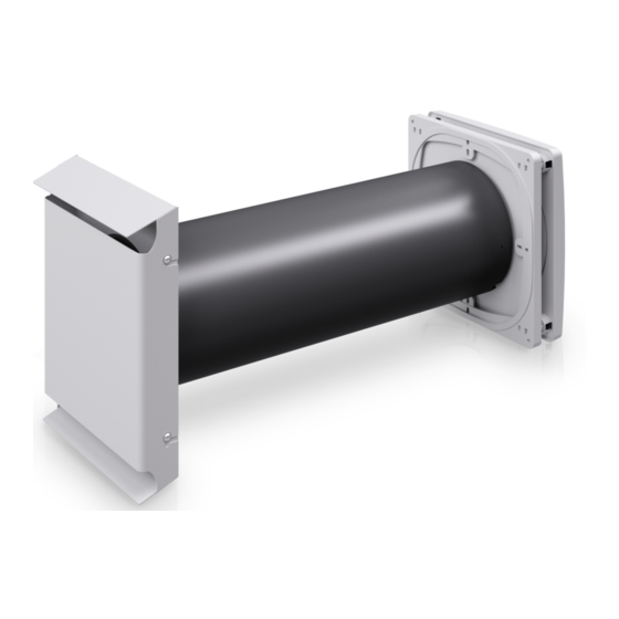
The standard length of the wall sleeve is 495 mm. For thicker walls, there is the option of ordering a wall sleeve with a length of 745 mm. Both versions can be trimmed on site. It is controlled via one of the following inVENTer system controllers • sMove s4 •... -
Page 9: Function
An air gap of about 10 mm below the door, unscrew the hinges by 5 mm, use a ventilation grille or similar (cross ventilation). The ventilation unit is controlled via one of the inVENTer system controllers. Depending on the controller, operating modes and functions may be selected. -
Page 10: Control Elements
SYS T E M OV E R V I E W Control elements sMove controller The controllers from the sMove product range are electronic control unit for controlling the iV-Smart ventilation units. They are characterised by their timeless and slim design and a simple touch-based operating concept. -
Page 11: Specifications
S P E C I F I CAT I O N S Specifications General specifications Feature Value Operating range [°C] -20 – 50 Extract air/Outdoor air Free from aggressive gases, dust and oils Air flow in reverse operation (push-pull) per unit 8.5 –... -
Page 12: Specifications According To Ec Directive For Energy Related Products
S P E C I F I CAT I O N S Specifications according to EC Directive for energy related products iV-Smart , local demand control: Product fiche iV-Smart according to VO 1254/2014 EU, dated 2014-07-11 Description Data Supplier's name inVENTer GmbH iV-Smart Supplier's model identifier iV-Smart Corner iV-Smart Ohio cold -88.068... - Page 13 S P E C I F I CAT I O N S iV-Smart , manual control: Product fiche iV-Smart according to VO 1254/2014 EU, dated 2014-07-11 Description Data Supplier's name inVENTer GmbH iV-Smart Supplier's model identifier iV-Smart Corner iV-Smart Ohio cold -82.062...
-
Page 14: Label According To Ec Directive For Energy Related Products
S P E C I F I CAT I O N S Label according to EC Directive for energy related products, regulation 1254/2014 [Germany] On the energy label you can find the following information from the product fiche: • Energy efficiency class (Specific energy consumption class) •... -
Page 15: Preparing For Installation / Installation Position
PREPARING FOR INSTALLATION / INSTALLATION POSITION Preparing for installation / Installation position • The exact positioning of the ventilation units and controllers must be determined on-site and, if necessary, adapted to the local conditions. Consult your planner! Installation is recommended in a suitable position in the upper wall area for optimal operation (approx. -
Page 16: Iv-Smart Ventilation Unit
I V- S M A R T+ V E N T I L AT I O N U N I T iV-Smart ventilation unit Construction Smart Nova Figure 1: Overview of iV-Smart Standard ventilation unit Components Exterior closure: weather Thermal accumulator insert protection hood (thermal accumulator and inVENTron) 1 Nova-R protective hood base plate... -
Page 17: Dimensions
I V- S M A R T+ V E N T I L AT I O N U N I T Dimensions Depth/ Height Designation Width [mm] Ø [mm] length [mm] [mm] Wall thickness with render [mm] > 270 Wall thick- Wall opening for wall sleeve –... - Page 18 I V- S M A R T+ V E N T I L AT I O N U N I T Exterior closure: Nova or Smart weather protection hood A ─ A Ø Nova protective hood cover Nova-R protective hood base plate Figure 3: Dimensioned drawing of Nova protective hood 1 Protective hood base plate 3 Protective hood cover...
- Page 19 I V- S M A R T+ V E N T I L AT I O N U N I T Position of wall opening ≥ 250 ≥ 250 Ø Ø With Smart protective hood With Nova protective hood Figure 5: Dimensioned drawing of wall opening iV-Smart (Interior view) 1 Wall opening: New building 4 Window reveal...
-
Page 20: Assembly And Installation
I V- S M A R T+ V E N T I L AT I O N U N I T Assembly and installation Additional required tools and materials Ø 6 mm Ø 180 mm Ø 8 mm 3 x 0.75 mm² Cable (braided flex), Wire ferrules with 3 x 0.75 mm²... - Page 21 I V- S M A R T+ V E N T I L AT I O N U N I T Checking the scope of supply Item no. 1506-0068 / 1506-0069 Item no. 1508-0080 Item no. 1508-0062 1508-0081 1508-0063 1508-0082 1508-0069 Item no.
- Page 22 I V- S M A R T+ V E N T I L AT I O N U N I T Install the wall sleeve (Item no. 1506-0068 / 1506-0069) X = ? X = ? A+B+[C]+D 1 – 2° 1-2°...
- Page 23 I V- S M A R T+ V E N T I L AT I O N U N I T Mount the weather protection hood A: Smart protective hood (Item no. 1508-0062 / 1508-0063 / 1508-0069) ø = 8 mm ...
- Page 24 I V- S M A R T+ V E N T I L AT I O N U N I T B: Nova protective hood (Item no. 1508-0080 / 1508-0081 / 1508-0082) ø = 8 mm iV-Smart ventilation system • Installation instructions...
- Page 25 I V- S M A R T+ V E N T I L AT I O N U N I T Insert thermal accumulator insert and connect the reversible fan A: Insert thermal accumulator and inVENTron (Item no. 1507-0017) Standard Slim X = ...
- Page 26 I V- S M A R T+ V E N T I L AT I O N U N I T B: Connect the fan BUS to the reversible fan Unit 1 Unit 2 Starting Direction: CCW Starting Direction: CW Supply Air (SUP) Extract Air (ETA) CW (–) CW (–)
- Page 27 I V- S M A R T+ V E N T I L AT I O N U N I T Attach Flair inner cover (Item no. 1505-0036 / 1505-0037) CLICK ø = 6 mm CLICK iV-Smart ventilation system • Installation instructions...
-
Page 28: Iv-Smart Corner Ventilation Unit
I V- S M A R T+ C O R N E R V E N T I L AT I O N U N I T iV-Smart Corner ventilation unit Construction Figure 7: Overview of iV-Smart Corner ventilation unit Components Exterior closure: Thermal accumulator insert... -
Page 29: Dimensions
I V- S M A R T+ C O R N E R V E N T I L AT I O N U N I T Dimensions Depth/ Height Designation Width [mm] Ø [mm] length [mm] [mm] Thickness Masonry and inner structure > 250 –... - Page 30 I V- S M A R T+ C O R N E R V E N T I L AT I O N U N I T Sectional drawing Installation length of the flat duct: L = ( ) +120 15 ≤...
- Page 31 I V- S M A R T+ C O R N E R V E N T I L AT I O N U N I T Wall opening ≥ 250 ≥ 350 Ø Ø Corner flat duct 400 mm Corner flat duct 500 mm Figure 9: Dimensioned drawing of wall opening with flat duct (Interior view) 1 Wall opening: New building (Simplex as...
- Page 32 I V- S M A R T+ C O R N E R V E N T I L AT I O N U N I T Exterior closure 1 Upper drip rail Ø 2 Louvres 3 Bottom drip rail 4 Through hole (2 x) 5 Condensate drip 28,1...
-
Page 33: Assembly And Installation
I V- S M A R T+ C O R N E R V E N T I L AT I O N U N I T Assembly and installation Additional required tools and materials Ø 6 mm Ø 180 mm Ø... - Page 34 I V- S M A R T+ C O R N E R V E N T I L AT I O N U N I T Checking the scope of supply Item no. 1506-0068 / 1506-0069 Item no. 1506-0066 Item no.
- Page 35 I V- S M A R T+ C O R N E R V E N T I L AT I O N U N I T Install the wall sleeve (Item no. 1506-0068 / 1506-0069) X = ? X = ? 1 –...
- Page 36 I V- S M A R T+ C O R N E R V E N T I L AT I O N U N I T Mount the Corner flat duct (Item no. 1506-0066 / 1506-0067) y ≥ 250 15 ≤ z ≤ 35 □ Ø / 1 – 2° 1–2°...
- Page 37 I V- S M A R T+ C O R N E R V E N T I L AT I O N U N I T > 1 Mount the reveal grille (Item no. 1508-0030 / 1508-0065) iV-Smart ventilation system •...
- Page 38 I V- S M A R T+ C O R N E R V E N T I L AT I O N U N I T Insert thermal accumulator insert and connect the reversible fan A: Insert thermal accumulator and inVENTron (Item no. 1507-0017) Standard Slim X = ...
- Page 39 I V- S M A R T+ C O R N E R V E N T I L AT I O N U N I T B: Connect the fan BUS to the reversible fan Unit 1 Unit 2 Starting Direction: CCW Starting Direction: CW Supply Air (SUP) Extract Air (ETA)
- Page 40 I V- S M A R T+ C O R N E R V E N T I L AT I O N U N I T Attach Flair inner cover (Item no. 1505-0036 / 1505-0037) CLICK ø = 6 mm CLICK iV-Smart ventilation system...
-
Page 41: Iv-Smart + Ohio Ventilation Unit
I V- S M A R T+ O H I O V E N T I L AT I O N U N I T iV-Smart Ohio ventilation unit Construction Figure 13: Overview of iV-Smart Ohio ventilation unit Components Exterior closure: Ohio weather Thermal accumulator insert protection hood (thermal accumulator and inVENTron) -
Page 42: Dimensions
I V- S M A R T+ O H I O V E N T I L AT I O N U N I T Dimensions Depth/ Height Designation Width [mm] Ø [mm] length [mm] [mm] Wall thickness > 180 –... - Page 43 I V- S M A R T+ O H I O V E N T I L AT I O N U N I T Wall opening ≥ 250 Ø Figure 16: Dimensioned drawing of wall opening iV-Smart Ohio (Interior view) 1 Wall opening: New buildings 4 Window reveal (Simplex as an option)
- Page 44 I V- S M A R T+ O H I O V E N T I L AT I O N U N I T Weather protection hood M4x0,7 (4x) Ø Figure 17: Dimensioned drawing of Ohio protective hood 1 Attachment points for protective grille 5 Protective grille 2 Neopor insert 6 Louvres...
-
Page 45: Assembly And Installation
I V- S M A R T+ O H I O V E N T I L AT I O N U N I T Assembly and installation Additional required tools and materials � 6 mm � 180 mm � 8 mm 3 x 0.75 mm²... - Page 46 I V- S M A R T+ O H I O V E N T I L AT I O N U N I T Checking the scope of supply Item no. 1506-0068 / 1506-0069 Item no. 1508-0019 Item no. 1508-0072 Item no.
- Page 47 I V- S M A R T+ O H I O V E N T I L AT I O N U N I T Install the wall sleeve (Item no. 1506-0068 / 1506-0069) X = ? X = ? A+B+D 1 –...
- Page 48 I V- S M A R T+ O H I O V E N T I L AT I O N U N I T Mount the Ohio protective hood (Item no. 1508-0072) 180° ø = 8 mm 180° ...
- Page 49 I V- S M A R T+ O H I O V E N T I L AT I O N U N I T iV-Smart ventilation system • Installation instructions...
- Page 50 I V- S M A R T+ O H I O V E N T I L AT I O N U N I T Insert thermal accumulator insert and connect the reversible fan A: Insert thermal accumulator and inVENTron (Item no. 1507-0017) Standard Slim X = ...
- Page 51 I V- S M A R T+ O H I O V E N T I L AT I O N U N I T B: Connect the fan BUS to the reversible fan Unit 1 Unit 2 Starting Direction: CCW Starting Direction: CW Supply Air (SUP) Extract Air (ETA) CW (–)
- Page 52 I V- S M A R T+ O H I O V E N T I L AT I O N U N I T Attach Flair inner cover (Item no. 1505-0036 / 1505-0037) CLICK ø = 6 mm CLICK iV-Smart ventilation system •...
-
Page 53: Troubleshooting And Disposal
T R O U B L E S H O O T I N G A N D D I S P O S A L Troubleshooting and disposal Troubleshooting Fault Possible cause Remedy No electrical power. Check fuse. Check wiring for correct polarity. Installation error. - Page 54 T R O U B L E S H O O T I N G A N D D I S P O S A L Disassembly Disassemble the ventilation unit in the opposite sequence to the assembly sequence. You can subsequently dispose of your old equipment/system. Please note the disposal recommendation outlined below.
-
Page 55: Guarantee And Warranty
Manufacturer guarantee inVENTer GmbH provides a five-year guarantee for all electrical components and the wall sleeve, as well as a thirty-year guarantee on the heat accumulator ceramic. This covers premature product wear. It affects in no way the applicable law. -
Page 56: Appendix 1: Terminal Assignment: Reversible Fan
A P P E N D I X 1: T E R M I N A L A S S I G N M E N T: R E V E R S I B L E FA N Appendix 1: Terminal assignment: reversible fan Plug (Cable from controller) Socket (Cable from fan) -
Page 57: Appendix 2: Wiring Protocol
A P P E N D I X 2 : W I R I N G P R O TO C O L Appendix 2: Wiring protocol Starting direction Ventila- Ventilation zone Floor Area/room and position tion unit (CAM) Supply Extract iV-Smart ventilation system... - Page 58 A P P E N D I X 1: T E R M I N A L A S S I G N M E N T: R E V E R S I B L E FA N Starting direction Ventila- Ventilation zone Floor...
- Page 59 HOMEPAGE: WWW.INVENTER.EU CEO: ANNETT WETTIG VAT ID NUMBER: DE 815494982 JENA DISTRICT COURT HRB 510380 PICTURE CREDITS: © INVENTER GMBH 2014-18 ALL RIGHTS RESERVED: © INVENTER GMBH 1999-2018 SUBJECT TO MODIFICATIONS. ALL INFORMATION IS SUPPLIED WITHOUT GUARANTEE. NO LIABILITY IS ACCEPTED FOR PRINTING ERRORS.
- Page 60 GmbH Ortsstraße 4a D-07751 Löberschütz +49 (0) 36427 211-0 +49 (0) 36427 211-113 info@inventer.de Version dated 05/2018 5005-0002 www.inventer.eu © inVENTer GmbH 1999-2018...
Need help?
Do you have a question about the iV-Smart+ and is the answer not in the manual?
Questions and answers