inVENTer iV14-Zero User And Safety Instructions
Hide thumbs
Also See for iV14-Zero:
- Installation instructions manual (44 pages) ,
- Operating instructions manual (36 pages) ,
- Manual (2 pages)
Table of Contents
Advertisement
Quick Links
Advertisement
Table of Contents

Related Manuals for inVENTer iV14-Zero


Summary of Contents for inVENTer iV14-Zero
- Page 1 Standard • Corner...
- Page 2 GmbH. The copyright of this document remains with the manufacturer. Rights to all contents and images: © inVENTer GmbH 1999-2018. All trademarks used in this document are the property of their respective manufacturers and are hereby acknowledged.
-
Page 3: Table Of Contents
Preparing for installation/mounting position ................ 15 iV14-Zero ventilation unit ......................16 Construction ........................16 ........................17 Assembly and installation ....................20 iV14-Zero Corner ventilation unit ................... 29 Construction ........................29 ........................30 Assembly and installation ....................34 Troubleshooting and disposal ....................44 Guarantee and warranty ...................... -
Page 4: User And Safety Instructions
U S E R A N D S A F E T Y I N S T R U C T I O N S User and safety instructions Thank you for purchasing this high quality product from inVENTer! This section provides an overview of the basic safety precautions for safe and proper operation of your ventilation unit. -
Page 5: Safety Instructions
Also note the safety instructions that precede the described handling instructions. Intended use The ventilation unit is designed to ventilate dwellings and similar residential spaces. It is controlled via an inVENTer system controller. General instructions • Observe the relevant standards, regulations and guidelines, especially the applicable association. - Page 6 • Are exposed to ambient temperatures below -20 °C and above 50 °C. • Contain obstacles that hinder access to, or removal of, the unit’s components. • it is used to dry up the structure. iV14-Zero ventilation system • Installation instructions...
- Page 7 Conformity The ventilation unit complies with the applicable technical safety requirements and standards for household and similar electrical appliances. They are conform to the following European directives: • • • • iV14-Zero ventilation system• Installation instructions...
-
Page 8: System Overview
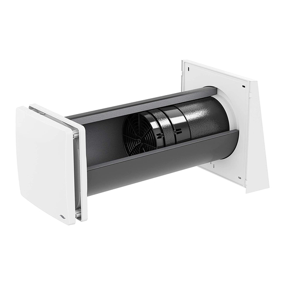
The construction of the iV14-Zero product range complies with the applicable European regulations. The ventilation unit iV14-Zero comprises a wall sleeve into which a thermal accumulator insert is installed. A closable inner cover conceals the ventilation unit visually discreet on the interior outside. -
Page 9: Function
These are operated in pairs in push-pull operation: One ventilation unit works in supply air mode while the other works in extract air mode at the same time. -
Page 10: Control Elements
They are characterised by their timeless and slim design and a simple touch-based operating concept. The sMove controller is available in the s4 and s8 versions. s4 is used to control up to four iV14-Zero ventilation units. s8 is used to control up to eight iV14-Zero ventilation units. unit completely. - Page 11 Type of protection (EN 60529) Automatically due to push-pull operation Frost protection (up to -20 °C) Max. 6,000 (with weather protection hood Nova Zero) Max. 6,800 (with exterior closure Corner Zero) Conformity local demand control manual control iV14-Zero ventilation system• Installation instructions...
- Page 12 Sound power level L 0.15 Control factor 0.65 n. a. n. a. Controller Regulated supply and exhaust grilles in the facade (one-direction devices only) Internet: www.inventer.eu 29.4 0.87 cold 90.25 average 46.13 warm 20.86 iV14-Zero ventilation system • Installation instructions...
- Page 13 S P E C I F I CAT I O N S Supplier's name inVENTer GmbH iV14-Zero iV14-Zero Corner cold -82.062 average -39.422 warm -14.995 Typology Type of drive installed Type of heat recovery system regenerative Sound power level L 0.15...
- Page 14 S P E C I F I CAT I O N S • • Sound power level L • Manual control iV14-Zero Corner control MZ-Home sMove without sMove sensors with sensors dB (A) · · ENERGIJA · ENERGY · ENERGIE 2016 1254/2014 iV14-Zero ventilation system • Installation instructions...
-
Page 15: Preparing For Installation/Mounting Position
1 between two ventilation units in push-pull operation (pair) in the same room to avoid the mixing of outdoor air and exhaust air: 1,2 m – 0,75 y 1,2 m 1,0 m 1,0 m 1,4 m iV14-Zero ventilation system• Installation instructions... -
Page 16: Iv14-Zero Ventilation Unit
I V14 - Z E R O V E N T I L AT I O N U N I T iV14-Zero ventilation unit Construction Standard version: Nova Zero Figure 1: Overview of iV14-Zero Standard ventilation unit Components Exterior closure: Standard version: (Thermal accumulator, inVENTron and... - Page 17 Nova Zero protective hood 23 – 88 incl. render, insulation, masonry and inner structure opened Sectional drawing 1 – 2° Figure 2: Sectional drawing iV14-Zero (side view) C Insulation B Masonry Render Inner cover base plate 6 Nova Zero protective hood...
- Page 18 Ø 8 mm, min. 50 mm deep (4 x) Position of wall opening Ø Position of wall opening Position of Simplex wall installation system Figure 4: Simplex installation system (Fig. 4, right) 6 Bottom edge of reveal iV14-Zero ventilation system • Installation instructions...
- Page 19 Figure 5: Inner cover base plate 2 Insert Flair Zero 6 Spacer (4 x) 3 Fan BUS feed-through 7 Interior wall attachment with Ø 6 mm, 4 Inner cover panel min. 40 mm deep (4 x) iV14-Zero ventilation system• Installation instructions...
-
Page 20: Assembly And Installation
ø 6 mm ø 225 mm ø 8 mm 3 x 0.75 mm² Cable (braided flex), Wire ferrules with 3 x 0.75 mm² collar 0.75 mm² Interior wall Exterior wall iV14-Zero ventilation system • Installation instructions... - Page 21 I V14 - Z E R O V E N T I L AT I O N U N I T Item no. 1508-0097 1508-0098 1508-0099 Item no. 1507-0018 Item no. 1505-0038 1507-0019 6 – 16 V DC CAM17 230 V AC (MZ-Home) 3x0.75 mm² sMove ø 225 1 – 2° iV14-Zero ventilation system• Installation instructions...
- Page 22 I V14 - Z E R O V E N T I L AT I O N U N I T X = ? 1 – 2° 1-2° 24 h iV14-Zero ventilation system • Installation instructions...
- Page 23 I V14 - Z E R O V E N T I L AT I O N U N I T (Item no. 1508-0097/1508-0098/1508-0099) ø = 8 mm iV14-Zero ventilation system• Installation instructions...
- Page 24 I V14 - Z E R O V E N T I L AT I O N U N I T iV14-Zero ventilation system • Installation instructions...
- Page 25 I V14 - Z E R O V E N T I L AT I O N U N I T Standard Slim 90° iV14-Zero ventilation system• Installation instructions...
- Page 26 I V14 - Z E R O V E N T I L AT I O N U N I T 3 x 0.75 mm² 3 x 0.75 III (–) IV (+) V (–) 6 – 16 V DC 230 V AC iV14-Zero ventilation system • Installation instructions...
- Page 27 I V14 - Z E R O V E N T I L AT I O N U N I T CW (–) CW (–) CCW (–) CCW (–) V (–) III (–) IV (+) IV (+) V (–) III (–) CHECK: iV14-Zero ventilation system• Installation instructions...
- Page 28 I V14 - Z E R O V E N T I L AT I O N U N I T CLICK iV14-Zero ventilation system • Installation instructions...
-
Page 29: Iv14-Zero Corner Ventilation Unit
I V14 - Z E R O C O R N E R V E N T I L AT I O N U N I T iV14-Zero Corner ventilation unit Construction Figure 6: Overview of iV14-Zero Corner ventilation unit Components Exterior closure:... - Page 30 I V14 - Z E R O C O R N E R V E N T I L AT I O N U N I T Dimensions Depth/length > 255 – – inner plaster Thickness Insulation > 120 – – Ø225 495 (745) Ø200 Reveal grille V-90x220 281.5 incl. render, insulation, masonry and inner structure opened iV14-Zero ventilation system • Installation instructions...
- Page 31 I V14 - Z E R O C O R N E R V E N T I L AT I O N U N I T Sectional drawing L = ( Figure 7: Sectional drawing iV14-Zero Corner ventilation unit E Render of reveal B Masonry...
- Page 32 Inner cover base plate 2 Insert Flair Zero (pre-assembled) 6 Spacer (4 x) 3 Fan BUS feed-through 7 Interior wall attachment with Ø 6 mm, 4 Inner cover panel min. 40 mm deep (4 x) iV14-Zero ventilation system • Installation instructions...
- Page 33 5 Condensate drip 28,1 Figure 10: 400 (500) Figure 11: 1 Fastening element (2 x) 5 Flat duct sliding sleeve 2 Sound insulation 6 Spacer (2 x) 3 Neopor insert 4 Ring insert Corner Zero iV14-Zero ventilation system• Installation instructions...
-
Page 34: Assembly And Installation
ø 6 mm ø 225 mm ø 8 mm 3 x 0.75 mm² Cable (braided flex), Wire ferrules with 3 x 0.75 mm² collar 0.75 mm² Interior wall Exterior wall iV14-Zero ventilation system • Installation instructions... - Page 35 [1001-0188] 1506-0101 Item no. 1506-0102 Item no. 1507-0018 Item no. 1505-0038 1507-0019 6 – 16 V DC CAM17 230 V AC (MZ-Home) 3x0.75 mm² sMove ø 225 1 – 2° iV14-Zero ventilation system• Installation instructions...
- Page 36 I V14 - Z E R O C O R N E R V E N T I L AT I O N U N I T X = ? 1 – 2° 1-2° 24 h iV14-Zero ventilation system • Installation instructions...
- Page 37 I V14 - Z E R O C O R N E R V E N T I L AT I O N U N I T Ø 1 – 2° 1–2° ø 8 mm 1 – 2° iV14-Zero ventilation system• Installation instructions...
- Page 38 I V14 - Z E R O C O R N E R V E N T I L AT I O N U N I T > 1 iV14-Zero ventilation system • Installation instructions...
- Page 39 I V14 - Z E R O C O R N E R V E N T I L AT I O N U N I T iV14-Zero ventilation system• Installation instructions...
- Page 40 I V14 - Z E R O C O R N E R V E N T I L AT I O N U N I T Standard Slim 90° iV14-Zero ventilation system • Installation instructions...
- Page 41 I V14 - Z E R O C O R N E R V E N T I L AT I O N U N I T 3 x 0.75 mm² 3 x 0.75 III (–) IV (+) V (–) 6 – 16 V DC 230 V AC iV14-Zero ventilation system• Installation instructions...
- Page 42 I V14 - Z E R O C O R N E R V E N T I L AT I O N U N I T CW (–) CW (–) CCW (–) CCW (–) V (–) III (–) IV (+) IV (+) V (–) III (–) CHECK: iV14-Zero ventilation system • Installation instructions...
- Page 43 I V14 - Z E R O C O R N E R V E N T I L AT I O N U N I T CLICK iV14-Zero ventilation system• Installation instructions...
-
Page 44: Troubleshooting And Disposal
Make sure, that the fan's type plate is Installation error. situated in direction of the thermal heat accumulator. Supply air is cold The controller is operating in Select heat recovery mode on the con- ventilation mode. troller. iV14-Zero ventilation system • Installation instructions... - Page 45 Recyclable material collection Recyclable material collection Sound insulation coating Inventin Recyclable material collection Flair Zero inner cover Recyclable material collection Thermal accumulator Ceramics Household waste Household waste Household waste Household waste enriched with Household waste Activated carbon iV14-Zero ventilation system• Installation instructions...
-
Page 46: Guarantee And Warranty
In the case of a warranty or guarantee claim, contact your local distributor or factory represen- tative. In all cases, return the complete device to the manufacturer. The guarantee is an additional Accessories and spare parts Technical customer service info@inventer.de iV14-Zero ventilation system • Installation instructions... -
Page 47: Appendix 1: Terminal Assignment: Reversible Fan
V (–) III (–) • The locking screws of the green BUS • The locking screws of the green BUS same direction. HINT: connected plug forms an "S" like "Supply" when starting in Supply air direction. iV14-Zero ventilation system• Installation instructions... -
Page 48: Appendix 2: Wiring Protocol
A P P E N D I X 2 : W I R I N G P R O TO C O L Appendix 2: Wiring protocol Starting direction Ventilation zone Floor Area/room and position tion unit (CAM) Supply Extract iV14-Zero ventilation system • Installation instructions... - Page 49 A P P E N D I X 2 : W I R I N G P R O TO C O L Starting direction Ventilation zone Floor Area/room and position tion unit (CAM) Supply Extract iV14-Zero ventilation system• Installation instructions...
- Page 50 A P P E N D I X 2 : W I R I N G P R O TO C O L iV14-Zero ventilation system • Installation instructions...
- Page 51 A P P E N D I X 2 : W I R I N G P R O TO C O L C O M PA N Y D E TA I L S INVENTER GMBH ORTSSTRASSE 4A GERMANY EMAIL: © INVENTER GMBH 2014-18 © INVENTER GMBH 1999-2018 iV14-Zero ventilation system• Installation instructions...
- Page 52 GmbH Ortsstraße 4a D-07751 Löberschütz +49 (0) 36427 211-0 +49 (0) 36427 211-113 info@inventer.de Version dated 07/2018 5007-0002 www.inventer.eu © inVENTer GmbH 1999-2018...
Need help?
Do you have a question about the iV14-Zero and is the answer not in the manual?
Questions and answers