inVENTer iV-Smart+ Installation Instructions Manual
Corner external termination
Hide thumbs
Also See for iV-Smart+:
- User manual (60 pages) ,
- Installation instructions manual (44 pages) ,
- Maintenance manual (2 pages)

Related Manuals for inVENTer iV-Smart+


Summary of Contents for inVENTer iV-Smart+
- Page 1 Installation instructions Corner external termination Corner flat duct 60x490x515 Corner iV-Twin+ flat duct 60x490x515 Reveal grille V-70x527 www.inventer.eu...
- Page 2 GmbH. ® The copyright to this document remains with the manufacturer. Rights to all content and images: © inVENTer GmbH 2021. All trademarks used in this document are the property of their respective manufacturers and are hereby acknowledged.
-
Page 3: Table Of Contents
Securing the flat duct to the exterior wall ................... 28 Fitting the reveal grille ....................... 31 Technical data ........................... 32 Scope of supply ..........................32 Disposal ............................. 32 Guarantee and warranty ........................33 Service ............................... 33 Corner variant of the inVENTer ventilation units | Installation instructions... -
Page 4: User And Safety Instructions
USER AND SAFETY INSTRUCTIONS User and safety instructions Thank you for purchasing this high quality product from inVENTer! This section provides an overview of the basic safety precautions for safe and proper operation of your ventilation system. User information Safety and warning instructions The safety and warning instructions in these installation instructions have a uniform structure and are marked with a symbol on the left side of the instruction. -
Page 5: Safety Instructions
The installation instructions are part of your iV14-MaxAir ventilation unit and must be available at all times (see www.inventer.de/downloads). When handing the system to a third party, the information regarding access to the installation instructions must be handed over also. - Page 6 The cleaning/care of components must not be carried out by children and/or persons who are not fully capable of doing so due to their physical, sensory or mental capabilities, inexperience or lack of knowledge. Corner variant of the inVENTer ventilation units | Installation instructions...
-
Page 7: Overview: Corner External Termination
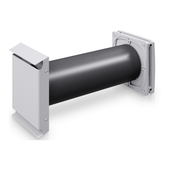
OVERVIEW: CORNER EXTERNAL TERMINATION Overview: Corner external termination The corner is an external termination for inVENTer ventilation units and comprises a flat duct and the reveal grille. It has been developed to integrate ventilation units in as inconspicuous a way as possible into exterior walls with insulation. -
Page 8: Dimensional Drawings
4 Fixing holes (4 x) Flat duct sliding sleeve Ø M3x0,5 1 Metal sleeve 2 Threaded hole (2x) 3 Fixing holes (4 x) Figure 3: Scale drawing of flat duct sliding sleeve Corner variant of the inVENTer ventilation units | Installation instructions... - Page 9 5 Air outlet 3 Pass-through drill hole (2 x) Flat duct separating insert Only used in conjunction with the inVENTer iV-Twin+ ventilation unit! 117,5 Figure 5: Scale drawing of flat duct separating insert Corner variant of the inVENTer ventilation units | Installation instructions...
-
Page 10: Preparing For Installation
Wall opening for wall sleeve Wall thickness �115 R-D103 wall sleeve 495 (745) �103 Corner flat duct 60x490x515 Reveal grille V-70x527 12.4 with masonry and plaster; insulation thickness at least 70 mm Corner variant of the inVENTer ventilation units | Installation instructions... - Page 11 Wall opening for wall sleeve �180 �225 ness Wall sleeve 495 (745) �160 �200 Corner flat duct 60x490x515 Reveal grille V-70x527 12.4 with masonry and plaster; insulation thickness at least 70 mm Corner variant of the inVENTer ventilation units | Installation instructions...
-
Page 12: Sectional Drawing Of The Installation Setup
2 Flat duct sliding sleeve with sealing tape 3 Flat duct The insulation thickness on the flat duct must be at least 10 mm. (y + z) must be min. 250 mm / max. 385 Corner variant of the inVENTer ventilation units | Installation instructions... - Page 13 2 Flat duct sliding sleeve with sealing tape 3 Flat duct The insulation thickness on the flat duct must be at least 10 mm. (y + z) must be min. 250 mm / max. 385 Corner variant of the inVENTer ventilation units | Installation instructions...
- Page 14 2 Flat duct sliding sleeve with sealing tape Ø 3 Flat duct The insulation thickness on the flat duct must be at least 10 mm. (y + z) must be min. 250 mm / max. 385 28,1 Corner variant of the inVENTer ventilation units | Installation instructions...
- Page 15 2 Flat duct sliding sleeve with sealing tape 3 Flat duct The insulation thickness on the flat duct must be at least 10 mm. (y + z) must be min. 250 mm / max. 385 Corner variant of the inVENTer ventilation units | Installation instructions...
- Page 16 2 Flat duct sliding sleeve with sealing tape 3 Flat duct The insulation thickness on the flat duct must be at least 10 mm. (y + z) must be min. 250 mm / max. 385 Corner variant of the inVENTer ventilation units | Installation instructions...
- Page 17 2 Flat duct sliding sleeve with sealing tape 3 Flat duct The insulation thickness on the flat duct must be at least 10 mm. (y + z) must be min. 250 mm / max. 385 Corner variant of the inVENTer ventilation units | Installation instructions...
-
Page 18: Installation And Assembly
2b Adapter with cut-out � 160 mm 7 Sealing tape 15 mm 2c Adapter with cut-out � 100 mm 3 Sliding sleeve with plaster protection (pre-fitted) incl. 4x fixing material Corner variant of the inVENTer ventilation units | Installation instructions... -
Page 19: Installation Instructions And Requirements
The wall sleeve matching your ventilation unit (� 100 mm, � 160 mm or � 200 mm) is installed. To install the wall sleeve, see the installation and operating instructions for your specific ventilation unit. Corner variant of the inVENTer ventilation units | Installation instructions... -
Page 20: Preparing For Installation
Make sure that the cut-out in the circumferential end-stop tape is placed in the lower area of the wall sleeve (condensate drip). The wall sleeve is prepared for installation. Corner variant of the inVENTer ventilation units | Installation instructions... -
Page 21: Preparing The Flat Duct
A: Installation on the right of the window reveal For installation on the left of the window reveal: ► Rotate the flat duct around 180°. B: Installation on the left of the window reveal Corner variant of the inVENTer ventilation units | Installation instructions... - Page 22 For installation on the left of the window reveal: ► Rotate the flat duct around 180°. B: Installation on the left of the window reveal The separating insert is secured in the flat duct. Corner variant of the inVENTer ventilation units | Installation instructions...
- Page 23 You have attached the sealing element to the separating insert. 1 Attached separating insert 2 Sealing element stuck in the centre Corner variant of the inVENTer ventilation units | Installation instructions...
-
Page 24: Cutting The Flat Duct To Size
You have determined the installation length L of the flat duct (y+z) + 130. ► Saw the flat duct to the determined installation length L. You have cut the flat duct to size. Corner variant of the inVENTer ventilation units | Installation instructions... - Page 25 ► Saw the flat duct together with the substructure panel to the determined installation length L. You have cut the flat duct and also the substructure panel to size. Corner variant of the inVENTer ventilation units | Installation instructions...
-
Page 26: Fitting The Sliding Sleeve
► Also secure the sealing tape on the inside to a cross-strut on the sliding sleeve. This cross- strut must be positioned at the bottom when the sliding sleeve is fitted to the flat duct. Corner variant of the inVENTer ventilation units | Installation instructions... - Page 27 4.5. Ensure that you measure up to the edge of the sliding sleeve. The plaster protec- tion is not included in the measurement. Corner variant of the inVENTer ventilation units | Installation instructions...
-
Page 28: Securing The Flat Duct To The Exterior Wall
► Drill the four holes with � 8 mm, min. 50 mm deep. When installing a iV-Twin+ Corner, there is no end-stop tape in the wall sleeve. The masonry is prepared. Corner variant of the inVENTer ventilation units | Installation instructions... - Page 29 ► Render the window reveal flush with the sliding sleeve. Take care not to apply render up to the plaster guard (render edge at the height of the sliding sleeve). The flat duct is installed. Corner variant of the inVENTer ventilation units | Installation instructions...
- Page 30 ► Render the window reveal flush with the sliding > 1 sleeve. Take care not to apply render up to the plaster guard (render edge at the height of the sliding sleeve). The flat duct is installed. Corner variant of the inVENTer ventilation units | Installation instructions...
-
Page 31: Fitting The Reveal Grille
► Screw the reveal grille to the flat duct. Make sure that the drip rail is directed towards the ground. You have fitted the reveal grille. The external termination is fitted. Corner variant of the inVENTer ventilation units | Installation instructions... -
Page 32: Technical Data
The table below contains disposal recommendations. Component Material Disposal Flat duct Neopor / EPS Recyclable material Sliding sleeve Stainless steel Scrap metal collection Powder-coated stainless steel | Reveal grille Scrap metal collection Powder-coated aluminium Corner variant of the inVENTer ventilation units | Installation instructions... -
Page 33: Guarantee And Warranty
Manufacturer warranty inVENTer GmbH provides a five-year warranty for all electrical components and the wall sleeve, as well as a 30-year warranty on the ceramic component of the thermal accumulator. This covers premature product wear. - Page 34 TECHNICAL DATA NOTES Corner variant of the inVENTer ventilation units | Installation instructions...
- Page 35 TECHNICAL DATA NOTES Corner variant of the inVENTer ventilation units | Installation instructions...
- Page 36 GmbH Ortsstraße 4a D-07751 Löberschütz Germany www.inventer.eu Subject to modifications. We accept no liability for printing errors. Item number: 5050-0005 Version: 1.0 – 05/2021...
Need help?
Do you have a question about the iV-Smart+ and is the answer not in the manual?
Questions and answers