inVENTer iV-Twin+ Installation Instructions Manual
Ventilation device with heat recovery
Hide thumbs
Also See for iV-Twin+:
- Installation and operating instructions manual (25 pages) ,
- Installation instructions manual (36 pages)

Subscribe to Our Youtube Channel
Related Manuals for inVENTer iV-Twin+


Summary of Contents for inVENTer iV-Twin+
- Page 1 Installation instructions iV-Twin+ Ventilation device with heat recovery www.inventer.eu...
-
Page 2: Table Of Contents
This documentation is updated regularly. Necessary corrections and appropriate supplements are Specifications according to ErP Directive, Regulation 1254/2014 ......... 36 always included in subsequent editions. You can also find the latest version at www.inventer.eu/ Specifications according to ErP Directive, Regulation 1254/2014 ......... 37 downloads. -
Page 3: User Information
The safety instructions and warnings contain the following information: attics. It is controlled via a controller of the inVENTer system (also referred to as "controller" in the following text). - Page 4 The full text of the EU Declaration of Conformity is available at the following Internet plug connections must be positioned in the wall sleeve at the rear of the fan device. address: https://www.inventer.eu/downloads/ • NOTICE: The ventilationdevice operates with protective extra-low voltage. It muss not be con- nected directly to the 230 Vpower supply system.
-
Page 5: Construction
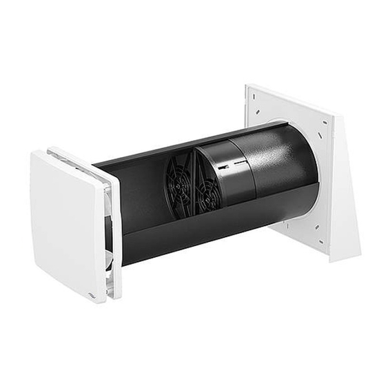
495 mm. For larger wall thicknesses, a wall sleeve with a length of 745 mm or 495 can be ordered. Both versions can be shortened on site. Figure 1: iV-Twin+ ventilation device overview The ventilation unit is controlled via one of the following controllers of the inVENTer system: • Pure • MZ-Home Components •... -
Page 6: Functions
Both reversing fans are switched to extract air mode The operation of the iV ventilation systems is intuitive with the matching inVENTer controllers. at the same time, i.e. both fans simultaneously con- Different operating modes or air volume flows can be set individually. The iV-Twin+ must be vey used extract air from the interior to the outside. -
Page 7: Control Elements
SYSTEM OVERVIEW VENTILATION DEVICE IV-TWIN+ SYSTEM OVERVIEW VENTILATION DEVICE IV-TWIN+ Control elements Multi-zone control The ventilation device is operated via a controller of the inVENTer system. Designation MZ-Home Depending on the controller different operating modes and functions can be set. -
Page 8: Preparing For Installation
PREPARING FOR INSTALLATION PREPARING FOR INSTALLATION Preparing for installation Position of the wall opening Installation Position External termination Ventilation device Variante Standard montieren • The installation location can be derived from the positioning proposal of the ventilation planning. The exact positioning of the individual devices and control units must be checked by the customer and adjusted on site if necessary. -
Page 9: Sectional Drawings Ventilation Device
PREPARING FOR INSTALLATION PREPARING FOR INSTALLATION Sectional drawings ventilation device Dimensional drawings of the components Flair Twin+ inner panel For sectional drawings of other variants of your ventilation unit, see the installation instructions A - A for your specific external termination. Schnittzeichnung Ventilation device iV-Twin+, Standard variant □... -
Page 10: Installation And Assembly
INSTALLATION AND ASSEMBLY INSTALLATION AND ASSEMBLY Installation and assembly Create wall opening Read this chapter carefully before installation to avoid installation errors. The installtion and connection of the ventilation device must be carried out by qualfied personnel. CAUTION: Falling masonry when creating the wall opening can lead to physical injuries and /or damage to property! Check the scope of supply •... -
Page 11: Laying Cables To The Wall Opening Of The Ventilation Device
INSTALLATION AND ASSEMBLY INSTALLATION AND ASSEMBLY Laying cables to the wall opening of the ventilation device Principle diagrams for cable laying CAUTION: The corresponding connection diagrams and assembly steps for installing the controller are not Exposed electrical components. part of this documentation! They can be found in the installation instructions of the respective Electric shock and injury due to live components (16 V DC)! control unit (Pure, sMove, MZ-Home). -
Page 12: Installing The Wall Sleeve
INSTALLATION AND ASSEMBLY INSTALLATION AND ASSEMBLY Installing the wall sleeve ► Remove the styrofoam discs from the wall sleeve. 12 h ► Insert the wall sleeve into the wall opening so it is Measuring tape, angle grinder, spirit level, non-pressing 2K polyurethane foam, flush with the interior wall. - Page 13 INSTALLATION AND ASSEMBLY INSTALLATION AND ASSEMBLY Installing the external termination Standard variant ► Insert the styrofoam discs into the wall sleeve from the inside and outside. The assembly of any exterior termination variants is not part of this documentation! It can be found in the installation instructions of the respective external closure. NOTICE: Interruption of the thermal insulation composite system.
-
Page 14: Inserting Separating Element
INSTALLATION AND ASSEMBLY INSTALLATION AND ASSEMBLY Inserting separating element TIP: Do not apply the sealing tape until inme- diately before installing the base plate. This prevents the sealing tape from swelling too NOTICE: IF the separating element is not positioned in the wall sleeve or is positioned incorrect- much and makes installation easier. - Page 15 INSTALLATION AND ASSEMBLY INSTALLATION AND ASSEMBLY Insert the heat accumulator, shorten the fan BUS, strip the insulation and connect it to the iV-Twin+ connection cable. NOTICE: • Ensure the correct sequence of the wire colours so that the fans start. NOTICE Do not store/stack the thermal accumulator insert outside the wall sleeve as doing so will damage the thermal accumulator's ceramic.
-
Page 16: Insert Xenion Reversible Fan, Connect And Check Functions
INSTALLATION AND ASSEMBLY INSTALLATION AND ASSEMBLY Insert Xenion reversible fan, connect and check functions NOTICE: Incorrect electrical connection will damage The mounting of the conversier fans varies depending on the place of use: the fan motor! • Use in protection zone 2 and higher (standard) •... - Page 17 INSTALLATION AND ASSEMBLY INSTALLATION AND ASSEMBLY Use in protection zone 1 (IPX4) ► The cables and plug connections are pushed into the wall sleeve and thus placed between the CAUTION: INcorrect positioning of the cables and plug connections leads to personal injury heat storage unit and the fan unit.
-
Page 18: Fitting The Inner Panel
-20 °C) • The position arrows on the back of the inner panel cover point upwards. Comformity • Check: The inVENTer logo is located at the bottom right. • The separating element is inserted into Energy efficiency class (SEC class) A+ / A the receptacle of the inner panel. -
Page 19: Specifications According To Erp Directive, Regulation 1254/2014
VO 1254/2014 EU dated 11 July • Energy efficiency class (SEC class) 2014 • Sound power level L • Maximum air flow (supply air) Description Values Supplier inVENTer GmbH iV-Twin+ Model identifier iV-Twin+ Corner iV-Twin+ Nordic Demand con- Manually con- cold -90.439... -
Page 20: Scope Of Supply
Description Values All standard components are also available as spare parts. Further accessories and spare parts Supplier inVENTer GmbH can be found in the separate accessories overview. Contact your local distributor to order components for your ventilation system. iV-Twin+ Model identifier... -
Page 21: Troubleshooting
Guarantee: Fan defective. Replace fan. Controller/power supply inVENTer GmbH gives a 5-year guarantee on all electronic components and the wall sleeve, as Switching controller/ power supply. defective. well as a 30-year guarantee on the ceramics of the thermal heat accumulator. - Page 22 GmbH Ortsstraße 4a D-07751 Löberschütz www.inventer.eu Subject to modifications No liability for printing errors Product Number 5001-00XX Version: 1.0 – 09/2022...
Need help?
Do you have a question about the iV-Twin+ and is the answer not in the manual?
Questions and answers