Table of Contents
Advertisement
Quick Links
Advertisement
Table of Contents

Subscribe to Our Youtube Channel
Related Manuals for inVENTer iV-Smart+ sMove


Summary of Contents for inVENTer iV-Smart+ sMove
- Page 1 iV-Smart sMove Operating instructions...
-
Page 2: Table Of Contents
Removing the thermal accumulator insert ............... 23 Cleaning and reassembling the thermal accumulator insert ..........24 Rights to all contents and images: © inVENTer GmbH 1999-2018. Attaching the inner cover ....................26 All trademarks used in this document are the property of their respective Troubleshooting and disposal .................... -
Page 3: User And Safety Instructions
When handing the equipment/system to a third party, the operating instructions must be handed Your inVENTer product is an exclusive system for the ventilation of your living premises, which over also. Please read the operating instructions carefully before operating or cleaning the... -
Page 4: System Overview
SYS T E M OV E R V I E W System overview • • Use the sMove controllers exclusively to control inVENTer ventilation devices with heat recovery. The iV-Smart ventilation system is designed to ventilate living rooms and bedrooms in single- If your device has a defect, contact your nearest distributor or our technical service. -
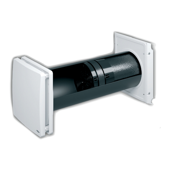
Page 5: Construction
4 Wall bracket (2 x) 12 Slim guiding vane (slim) 13 Guiding vane knob The ventilation unit is controlled via one of the inVENTer system controllers. Depending on the controller, operating modes and functions may be selected. Flair inner cover... -
Page 6: Control Elements
SYS T E M OV E R V I E W O P E R AT I O N O F T H E I V- S M A R T+ V E N T I L AT I O N U N I T Operation of the iV-Smart ventilation unit Control elements... -
Page 7: Operating The Smove Controllers
Mode button displays the currently set mode. Operating mode, output level and further functions, i. e. pause function, are adjusted via one of the inVENTer system controllers The output level of the ventilation unit can be adjusted in all operating modes. -
Page 8: Activating The Controller
O P E R AT I N G T H E S M OV E C O N T R O L L E R S O P E R AT I N G T H E S M OV E C O N T R O L L E R S The external interface is a bi-functional port on the back of the operating unit. -
Page 9: Setting Mode
O P E R AT I N G T H E S M OV E C O N T R O L L E R S O P E R AT I N G T H E S M OV E C O N T R O L L E R S Setting mode Setting pause function mode Setting heat recovery mode... -
Page 10: Set Output
O P E R AT I N G T H E S M OV E C O N T R O L L E R S O P E R AT I N G T H E S M OV E C O N T R O L L E R S Set output View hours run The intensity of the ventilation can be adjusted continuously by moving the slide control, or... -
Page 11: Remove The Inner Cover Panel
Remove the reveal grille. Clean the interior side of Flat duct Recommended maintenance The maintenance tasks and intervals listed here are recommended by inVENTer GmbH to maintain the functionality and performance of the iV-Smart ventilation system. Remove the inner cover panel Depending on requirements and/or air quality, your personal maintenance plan may deviate from these recommendations. -
Page 12: Removing The Thermal Accumulator Insert
You have removed the thermal accumulator insert. Place the cover on the four spacers. Ensure that the inVENTer logo is located on the bottom right). Press the side detent lugs inwards on the inner cover base plate's spacers. -
Page 13: Cleaning And Reassembling The Thermal Accumulator Insert
C L E A N I N G A N D M A I N T E N A N C E C L E A N I N G A N D M A I N T E N A N C E Cleaning and reassembling the thermal accumulator insert Step 1: Clean both parts of the guiding vane care- Soft brush, lint-free soft cloth and warm water... -
Page 14: Attaching The Inner Cover
Place the cover on the four spacers. Slide the thermal accumulator into the sleeve. wall sleeve as far as the end stop tape. Ensure that the inVENTer logo is located on the bottom right. Fan speed very high. Set a lower output level on the controller. - Page 15 T R O U B L E S H O O T I N G A N D D I S P O S A L S P E C I F I CAT I O N S Possible cause Remedy Wrong controller Check position of the jumper on the back...
- Page 16 AC C E S S O R I E S A N D S PA R E PA R T S AC C E S S O R I E S A N D S PA R E PA R T S Accessories and spare parts Item number sMove controller...
- Page 17 Manufacturer guarantee mounting sleeve, as well as a thirty-year guarantee on the heat accumulator ceramic. This covers premature product wear. Further information about the warranty is available at www.inventer.eu/guarantee. Service Warranty and guarantee claims In the case of a warranty or guarantee claim, contact your local distributor or factory representative.
-
Page 18: Appendix 2: Cleaning Protocol
HOMEPAGE: WWW.INVENTER.EU CEO: ANNETT WETTIG VAT ID NUMBER: DE 815494982 JENA DISTRICT COURT HRB 510380 PICTURE CREDITS: © INVENTER GMBH 1999-2018 Cleaning/ Control measure: Controlled (C) / Cleaned (R) / Changed (W) Designation / Scope Action ALL RIGHTS RESERVED: © INVENTER GMBH 1999-2018... - Page 19 GmbH Ortsstraße 4a D-07751 Löberschütz +49 (0) 36427 211-0 +49 (0) 36427 211-113 info@inventer.de Version dated 05/2018 Subject to modi cations. Item number: 5005-0004 www.inventer.eu © inVENTer GmbH 1999-2018...
Need help?
Do you have a question about the iV-Smart+ sMove and is the answer not in the manual?
Questions and answers