inVENTer MZ-Home Installation Instructions Manual
Hide thumbs
Also See for MZ-Home:
- User manual (60 pages) ,
- Operating instructions manual (36 pages) ,
- Operating instructions manual (44 pages)
Table of Contents
Advertisement
Quick Links
Advertisement
Table of Contents

Related Manuals for inVENTer MZ-Home


Summary of Contents for inVENTer MZ-Home
- Page 1 Installation instructions MZ-Home Control device www.inventer.eu...
- Page 2 GmbH. ® The copyright to this document remains with the manufacturer. Rights to all content and images: © inVENTer GmbH 2022. All trademarks used in this document are the property of their respective manufacturers and are hereby acknowledged.
-
Page 3: Table Of Contents
Commissioning ........................34 Function test........................34 Coupling ......................... 35 Start screen ........................36 Overview of the MZ-Home menu structure ..............37 Technical data .......................... 38 Scope of supply ........................39 Accessories and spare parts ....................39 10 Troubleshooting and disposal ....................40 Guarantee and warranty ...................... -
Page 4: User And Safety Instructions
USER AND SAFETY INSTRUCTIONS User and safety instructions Thank you for purchasing this high quality product from inVENTer! This section provides an overview of the basic safety precautions for safe and proper operation of your controller. User information Safety and warning instructions concept The safety and warning instructions in these installation instructions have a uniform structure and are marked with a symbol on the left side of the instruction. -
Page 5: Safety Instructions
USER AND SAFETY INSTRUCTIONS Safety instructions The installation instructions are part of your MZ-Home controller and must be available at all times (see www.inventer.eu/downloads). When handing the system to a third party, the information regarding access to the installation instructions must be handed over also. - Page 6 Any kind of use other than the intended use will exclude all liability claims. Improper use The MZ-Home controller is intended exclusively for the control of the ventilation units specified in the section on intended use. Any other use is strictly prohibited.
-
Page 7: System Overview: Mz-Home Controller
/ iV14-Zero / iV-Light / iV-Compact iV14-MaxAir / iV-Office / iV-Twin+ On the MZ-Home controller, the operating mode of the ventilation unit, the setting of the air volume flow, the programming of a weekly timer and the automatic humidity monitoring is set separately for each zone. -
Page 8: Construction
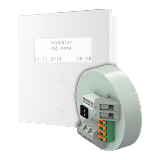
SYSTEM OVERVIEW: MZ-HOME CONTROLLER Construction The MZ-Home controller consists of a programming unit and at least one up to a maximum of 4 Clust-Air module(s). The operating unit is mounted directly on the interior wall by means of a mounting box. It serves as an operating and display interface for the user. -
Page 9: Function
SYSTEM OVERVIEW: MZ-HOME CONTROLLER Function The MZ-Home controller is a control unit for decentralised ventilation units with heat recovery from inVENTer GmbH. Thanks to its unique Clust-Air technology (zone control), the MZ-Home controller is able to control up to four areas (zones) within an accommodation unit separately from each other. For each zone, the operating mode and output level can be set manually or via a weekly timer. - Page 10 Clust-Air module for the respective zone to ventilation mode with the air volume flow rate set on the controller. If the value falls below the limit value, the MZ-Home controller switches back to the previously set operating mode and ventilation level after a 20-minute run-on time.
- Page 11 SYSTEM OVERVIEW: MZ-HOME CONTROLLER Sensor Input Limit value exceeded Limit value not reached Change all ventilation units Change all ventilation units sensor External on the Clust-Air module to on the Clust-Air module to VOC sensor switching ventilation mode. the originally set operating contact mode.
- Page 12 8.00 ≤ U ≤ 8.50 When connecting an analogue input to the Clust-Air module, the Analogue input for the respec- tive zone must be selected in the Settings main menu ( MZ-Home operating instructions). Deactivate interface The interface on the Clust-Air module can be deactivated in the Settings (main menu (...
-
Page 13: Mz-Home Controller Factory Settings
SYSTEM OVERVIEW: MZ-HOME CONTROLLER MZ-Home controller factory settings On delivery from the factory, the MZ-Home controller is configured with the following default settings: Feature Specification Value Ventilation level Ventilation level 1 All zones and operating modes 25 % Ventilation level 2... -
Page 14: Operating And Display Element: Programming Unit
Only use the following cable cross-sections: • Power cable: max. 1.5 mm² • Fan BUS: min. 0.75 mm² – max. 33 m length with star-shaped connection of the fans to the Clust-Air module • Control BUS: 0.25 – 0.5 mm² MZ-Home | Installation instructions... - Page 15 20 m Fan: Star-shaped connection 20 m Xenion EFP; Mini-Xenion Connection in series 10 m Humidity and J-Y(ST)Y-2x2x0.8 between control module and sensor 15 m temperature sensor Maximum distance between Clust-Air module and last connected ventilation unit MZ-Home | Installation instructions...
-
Page 16: Wiring Options
I I I IV I I I I I I IV I I I VI VII VIII IX VII VIII Figure 6: Connection example for the MZ-Home controller (connection of the fans to the module in series) MZ-Home | Installation instructions... - Page 17 GND ( ┴ ) DIR1 (III) GND ( ┴ ) + 24 V Figure 7: Wiring rear of MZ-Home operating unit and Clust-Air module (Connection of the ventilation units to the module in a star configuration) MZ-Home | Installation instructions...
-
Page 18: Interfaces And Terminal Assignment
3 4 5 6 DC 24 V AC 230 V Figure 8: Interfaces for MZ-Home switching Figure 9: Interfaces on the rear of the MZ-Home power supply unit operating unit Clust-Air module (control module and humidity and temperature sensor) Control module... -
Page 19: Terminal Assignments
+ 24 V Controller operating voltage supply unit / Controller 5, 6 GND ( ┴ ) operating voltage Rear of MZ-Home controller operating unit (Fig. 9) MZ-Home operating unit GND ( ┴ ) Controller operating voltage operating voltage + 24 V Connection terminal GND ( ┴... -
Page 20: Zone Assignment On The Dip Switch Of The Clust-Air Module
The ventilation zone is assigned at the DIP switch on the Clust-Air module. Structure of the DIP switch 1 Housing 2 Mini-Switch 3 Number Mini-Switch 4 Sliding Switch Figure 12: Position and structure of the DIP switch MZ-Home | Installation instructions... - Page 21 Switch 1 is switched off. The slide switch is set to 1. Switch 2 is switched on. The slide switch is in the ON position. Zone 4 Both switches are on. The slide switches are set to ON. MZ-Home | Installation instructions...
-
Page 22: Preparing For Installation
- in rooms which are free from aggressive or corrosive gases and extreme dust exposure. • The MZ-Home controller is installed on the interior wall via a mounting box. Recommended installation height: 1.50 m floor to lintel height (reachability for operation). -
Page 23: Principle Sketch: Connection Options For Ventilation Units
Installation elements Flush-mounted box 60x66 ‒ Flush-mounted plasterboard box 68x61 ‒ Control cabinet box ‒ Operating unit housing MZ-Home controller ‒ Top-hat rail switch-mode power supply unit (4 HP) ‒ Humidity/temperature sensor FTS15-MZ ‒ Table 1: Installation accessories and installation dimensions... -
Page 24: Dimensional Drawings Of Controller Components
2 Box fixing screw (4 x) 3 MZ-Home operating unit base plate Humidity and temperature sensor FTS15-MZ Figure 14: Dimensioned drawing of MZ-Home humidity and temperature sensor 1 Ventilation slots 2 Fixing points on base plate of humidity and temperature sensor (2 x) -
Page 25: Installation And Assembly
Check the delivery for completeness and transport damage upon receipt using the delivery note. Report missing items immediately. MZ-Home basic set 1 MZ-Home operating unit 2 Top-Hat rail switch-mode PSU MZ-Home 3 Control module CAM17 4 Terminating resistor 120 Ω 5 Lustre terminal for operating voltage cable... -
Page 26: Routing Wires And Attaching The Mounting Box
• The milled holes for the mounting box(es) on the interior wall are created: 1 mounting box per module. ► Route the wires needed to connect the controller to the installation site: A. Supply line between the control cabinet and the installation location of the MZ-Home operating unit: Top-hat rail switch-mode power supply unit: DC 24 V B. -
Page 27: Mounting The Clust-Air Modules
INSTALLATION AND ASSEMBLY Mounting the Clust-Air modules The MZ-Home operating unit is mounted on a mounting box. The first Clust-Air module is also connected in this. Distributing fan cables We recommend the star-shaped connection of fans to the relevant control module. The distribu- tion of wires to the fan in this case takes place within the prepared mounting box using 5-pole terminal blocks. - Page 28 INSTALLATION AND ASSEMBLY Connecting the control modules The control module contains the electronics for controlling the inVENTer ventilation devices with heat recovery within a ventilation zone, as well as a humidity and temperature sensor. The control module is placed in the mounting box after connection.
- Page 29 BUS. This is connected to the operating unit. On the last connected module: ► Attach the terminating resistor in the two middle poles (A and B) of the remaining double terminal, 4-pole, for the control BUS. MZ-Home | Installation instructions...
- Page 30 Do not cover the modules until the coupling (commissioning) has been completed, otherwise the indicator lights will no longer be visible for easy checking. Recommendation for covering the boxes for additional Clust-Air modules: • Cover in switch design. • Commercially available dummy cover for wallpapering over the box. MZ-Home | Installation instructions...
-
Page 31: Installing The Mz-Home Operating Unit
INSTALLATION AND ASSEMBLY Installing the MZ-Home operating unit The MZ-Home operating unit is mounted on a mounting box. We recommend mounting on the box in which the first Clust-Air module is also connected. Screws, screwdriver Requirements: • The operating voltage cable has been laid. -
Page 32: Connecting The Switching Power Supply Unit
• Centre-to-centre distance: 46 mm, horizontal • The drill holes are located in each case above or below the connection cable for the humidity and temperature sensor. The holes for the humidity and temperature sen- sor are in place. MZ-Home | Installation instructions... - Page 33 ► Fit the mounting pins on the cover into the pin guides on the base plate. The ventilation slots are aligned upwards and downwards. The humidity and temperature sensor is installed. MZ-Home | Installation instructions...
-
Page 34: Commissioning
Unrecognised devices connected to the MZ-Home controller cannot be coupled and therefore cannot be controlled! • Assign an address for each Clust-Air module via the DIP switch. • Check whether the MZ-Home controller has recognised all connected devices. Function test Requirements: •... -
Page 35: Coupling
Navigation arrow RIGHT Navigation arrow After approx. 30 seconds, the MZ-Home controller automatically switches to the start screen. By simultaneously pressing the navigation arrows and for longer than 5 seconds, you can manually switch to the start screen. -
Page 36: Start Screen
The start screen is the standard display when the MZ-Home controller is activated. The start screen displays the inVENTer logo, the current date and time. Depending on the situa- tion, current deviations are displayed on the start screen (e.g. no humidity sensor connected to a zone). -
Page 37: Overview Of The Mz-Home Menu Structure
COMMISSIONING Overview of the MZ-Home menu structure z o n e 1 s e t t i n g s i n V E N T e r t | r h | M Z - H o m e a c t : 2 9 °... -
Page 38: Technical Data
Potential-free normally open contact External switching contact (optional) (pressure sensor: NC or NO contact) Power consumption [W] Max. 18 Humidity and temperature sensor FTS15-MZ Feature Value Adjustment range humidity sensor [% rH] 40 – 80 Humidity sensor interval [%] MZ-Home | Installation instructions... -
Page 39: Scope Of Supply
Check the delivery for completeness and transport damage upon receipt using the delivery note. Report missing items immediately, and at the latest within 14 days to your supplier, distributor or factory representative. • MZ-Home operating unit • Switching power supply unit • Clust-Air module CAM17 (1 x) •... -
Page 40: Troubleshooting And Disposal
Information on how to do this can be found in 12: Service. Dismantling and disposal Dismantle the MZ-Home controller before disposal. Dispose of the product in compliance with the applicable national regulations. The products described in these installation and operating instructions are largely recyclable due to their low-pollutant processing. -
Page 41: Guarantee And Warranty
Outside Germany, the national guarantee provisions of the country in which the system is sold apply. Please contact the distributor for your country. Manufacturer warranty inVENTer GmbH provides a five-year warranty for electronic components. This covers premature product wear. Further information about the warranty is available at www.inventer.eu/guarantee... -
Page 42: Annex 1: Connection Log
ANNEX 1: CONNECTION LOG Annex 1: Connection log Starting direction Ventilation Ventilation zone Floor Room name and position Supply Exhaust device (CAM) MZ-Home | Installation instructions... - Page 43 ANNEX 1: CONNECTION LOG MZ-Home | Installation instructions...
- Page 44 GmbH Ortsstraße 4a 07751 Löberschütz Germany www.inventer.eu Subject to modifications. We accept no liability for printing errors. Item number: 5020-0019 Version: 1.0 – 06/2022...
Need help?
Do you have a question about the MZ-Home and is the answer not in the manual?
Questions and answers