inVENTer iV-Light Operating Instructions Manual
Hide thumbs
Also See for iV-Light:
- Installation instructions manual (40 pages) ,
- Maintenance manual (2 pages) ,
- Manual (2 pages)
Table of Contents
Advertisement
Quick Links
Advertisement
Table of Contents

Related Manuals for inVENTer iV-Light


Summary of Contents for inVENTer iV-Light
- Page 1 Operating instructions...
- Page 2 GmbH. The copyright of this document remains with the manufacturer. Rights to all contents and images: © inVENTer GmbH 1999-2018. All trademarks used in this document are the property of their respective manufacturers and are hereby acknowledged.
-
Page 3: Table Of Contents
System overview ........................7 Construction ........................8 Function ........................... 9 Control elements ......................10 Operation of the iV-Light ventilation unit ................11 Opening/closing the inner cover ..................11 Operating the sMove controllers ................... 12 Design and features ......................12 Activating the controller ....................15 Setting mode ........................ -
Page 4: User And Safety Instructions
User and safety instructions Thank you for purchasing this high quality product from inVENTer! Your inVENTer product is an exclusive system for the ventilation of your living premises, which additionally contributes to improving energy efficiency via the principle of heat recovery. Our inVENTer ventilation units are made to the highest quality standards in Germany using premium materials. -
Page 5: Safety Instructions
• Use the equipment/system exclusively for the applications that are described in this docu- mentation and only in conjunction with components that are recommended, authorised and described by inVENTer GmbH in this documentation. Changes or modifications to the equip- ment/system are not permitted. - Page 6 • Never use the unit without the filters and inner cover. • Use the sMove controllers exclusively to control inVENTer ventilation units with heat recovery. If your ventilation unit has a defect, contact your nearest distributor or our technical service.
-
Page 7: System Overview
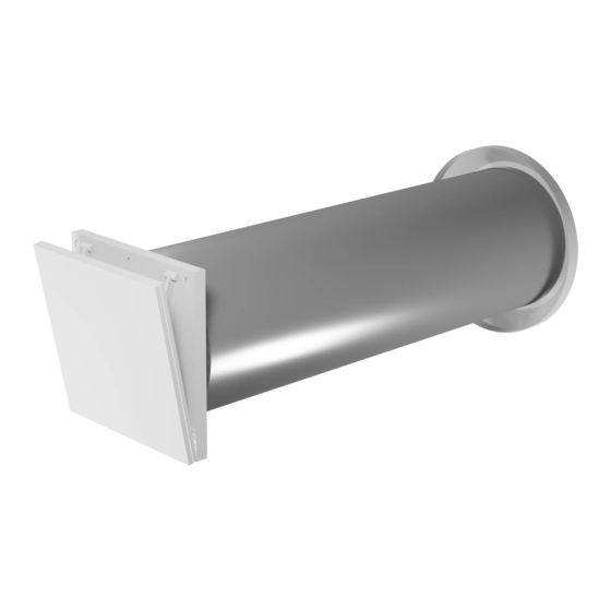
The construction of the iV-Light complies with the applicable European regulations. The iV-Light ventilation unit comprises a wall sleeve into which a thermal accumulator insert is installed. An inner cover with quick lock and in slim design conceals the ventilation unit visually discreet on the interior wall side. -
Page 8: Construction
SYSTEM OVERVIEW Construction Figure 1: Overview of iV-Light ventilation unit Components Exterior closure: Thermal accumulator insert Light protective grille (thermal accumulator and inVENTron) 1 Protective grille 6 Thermal accumulator with insulation 2 Fastening claws (2 x, pre-assembled) 7 Thermal accumulator handle... -
Page 9: Function
Due to the fan’s sensor technology it also has a high pressure stability: high pressure built-up and an active speed control (integrated wind stabiliser) keep the air flow within the system nearly constant (max. -
Page 10: Control Elements
The sMove controller is available in the s4 and s8 versions. s4 is used to control up to four iV-Light ventilation units. s8 is used to control up to eight iV-Light ventilation units. The connected ventilation units can be controlled in the following modes: •... -
Page 11: Operation Of The Iv-Light Ventilation Unit
OPERATION OF THE IV-LIGHT VENTILATION UNIT Operation of the iV-Light ventilation unit Opening/closing the inner cover For correct functioning of your ventilation system the ventilation unit’s inner cover must be opened. Close the inner cover if you take the ventilation unit out of operation. -
Page 12: Operating The Smove Controllers
The position of the illuminated display on the left side of the slide control indicates the currently set output level. The operating instructions for the MZ-Home controller are not part of this documentation. They are available separately. iV-Light ventilation system / sMove controller • Operating instructions... - Page 13 The position of the illuminated display on the left side of the slide control indicates the currently set output level. iV-Light ventilation system / sMove controller • Operating instructions...
- Page 14 (open) connected to the controller connected to the controller to to continuous ventilation the originally set mode. mode, output level 4. VOC sensor Jumper 1: Only for factory settings Hygrostat iV-Light ventilation system / sMove controller • Operating instructions...
-
Page 15: Activating The Controller
You can switch modes and change the output Ö level. If no change is made after the controller is activated, the controller will switch on the reversible fans at the lowest output level after 60 minutes. iV-Light ventilation system / sMove controller • Operating instructions... -
Page 16: Setting Mode
You have selected "continuous ventilation" mode. Ö TIP: Pressing the button again lets you switch between the "heat recovery" and "continu- ous ventilation" modes. iV-Light ventilation system / sMove controller • Operating instructions... - Page 17 ► Press the button longer than 5 seconds. The white Pause/Off indicator light is perma- Ö nently lit: 5 sec You have shut off the controller. Ö iV-Light ventilation system / sMove controller • Operating instructions...
-
Page 18: Set Output
You have set continuous output adjustment. Ö The 10th LED on the slider's left side marks 70 % output level. It can only be chosen when setting the output contiuous. iV-Light ventilation system / sMove controller • Operating instructions... -
Page 19: View Hours Run
End value: 7th indicator light to the left of slide control 7 running lights move to the end value The controller has been in operation for 0-4-0-7 days (407 days). Ö iV-Light ventilation system / sMove controller • Operating instructions... -
Page 20: Cleaning And Maintenance
• Vacuum cleaner Recommended maintenance The maintenance tasks and intervals listed here are recommended by inVENTer GmbH to maintain the functionality and performance of the iV-Light ventilation system. Depending on requirements and/or air quality, your personal maintenance plan may deviate from these recommendations. -
Page 21: Cleaning/Replacing Dust Filters
Cleaning/replacing dust filters TIP: inVENTer dust filters of class G4 are highly durable and can be washed repeatedly. We recommend cleaning the dust filter regularly. Requirements: The reversible fan is switched off on the controller. - Page 22 The cross-section of the wall sleeve is covered. ► Fold the panel back downwards. ► Audibly snap the panel into the base plate's bottom locking hooks. CLICK You have cleaned/changed the dust filter. Ö iV-Light ventilation system / sMove controller • Operating instructions...
-
Page 23: Removing The Thermal Accumulator Insert
► Step 1: Remove inVENTron from the wall sleeve by the knob. ► Step 2: Remove the thermal accumulator from the wall sleeve by the handle. You have removed the thermal accumulator insert. Ö iV-Light ventilation system / sMove controller • Operating instructions... -
Page 24: Cleaning And Reassembling The Thermal Accumulator Insert
► Turn the fan so that the remaining guiding vane is pointing upwards. ► Remove the guiding vanes from the fan. Remove the remaining guiding vane as previ- Ö ously described. iV-Light ventilation system / sMove controller • Operating instructions... - Page 25 (Appendix 1: Wiring protocol or 26) ► Slide inVENTron as far as the thermal accumulator. You have cleaned and re-installed the thermal Ö accumulator insert. iV-Light ventilation system / sMove controller • Operating instructions...
- Page 26 ► Re-insert the inner cover completely into the wall sleeve. Ensure that the inVENTer logo is located on the bottom right). ► Pull the inner cover panel on its upper edge into your direction until the quick-lock audibly releases.
-
Page 27: Troubleshooting And Disposal
Slide the thermal accumulator into the sleeve. wall sleeve as far as the end stop tape. Fan speed very high. Set a lower output level on the controller. iV-Light ventilation system / sMove controller • Operating instructions... - Page 28 Contact an electronic appliance disposal company to arrange environmentally friendly recycling and disposal of your old system. They will dispose of the product in compliance with the applicable national regulations. iV-Light ventilation system / sMove controller • Operating instructions...
-
Page 29: Specifications
6.7 – 15.3; 3 pole Analogue input (optional) [V DC] 0 – 10, Control voltage External switching contact (optional) Potential free closer contact (NO) Operating temperature [°C] 5 – 50 Conformity iV-Light ventilation system / sMove controller • Operating instructions... -
Page 30: Accessories And Spare Parts
Dust filter G4 IC Light V-220x220 (2 x) 1004-0175 Sound absorbing insert R-D160 1004-0148 Sound protector SPR R-D160 1004-0154 Wind protection insert WSE R-D160 1004-0151 Sensor CS1 1004-0145 Hygrostat HYG12 1002-0015 iV-Light ventilation system / sMove controller • Operating instructions... - Page 31 Connecting Element IC 100x42 3006-0294 Panel IC Light V-220x220 2003-0222 Controllers Control panel switching PSU NT17-s4 3002-0274 Flush-mounted switching PSU NT17-s4 3002-0273 Control panel switching PSU NT17-s8 3002-0275 Flush-mounted switching PSU NT17-MZ/s8 3002-0267 iV-Light ventilation system / sMove controller • Operating instructions...
-
Page 32: Guarantee And Warranty
Failure to observe the intended use will invalidate all warranty claims. Manufacturer guarantee inVENTer GmbH provides a five-year guarantee for all electrical components and the wall mounting sleeve, as well as a thirty-year guarantee on the heat accumulator ceramic. This covers premature product wear. -
Page 33: Appendix 1: Wiring Protocol
APPENDIX 1: WIRING PROTOCOL Appendix 1: Wiring protocol Starting direction Ventila- Ventilation zone Floor Area/room and position Supply Extract tion unit (CAM) iV-Light ventilation system / sMove controller • Operating instructions... -
Page 34: Appendix 2: Cleaning Protocol
(depending on filter type) Filter: Check, clean or change if necessary (depending on filter type) Thermal accumulator, Xenion reversible fan, guiding vanes, Cleaning Inventin Accessories Check, clean or change if necessary iV-Light ventilation system / sMove controller • Operating instructions... - Page 35 JENA DISTRICT COURT HRB 510380 PICTURE CREDITS: © INVENTER GMBH 1999-2018 ALL RIGHTS RESERVED: © INVENTER GMBH 1999-2018 SUBJECT TO MODIFICATIONS. ALL INFORMATION IS SUPPLIED WITHOUT GUARANTEE. NO LIABILITY IS ACCEPTED FOR PRINTING ERRORS. iV-Light ventilation system / sMove controller • Operating instructions...
- Page 36 GmbH Ortsstraße 4a D-07751 Löberschütz +49 (0) 36427 211-0 +49 (0) 36427 211-113 info@inventer.de Version dated 07/2018 Subject to modifications. Item number: 5008-0003 www.inventer.eu © inVENTer GmbH 1999-2018...
Need help?
Do you have a question about the iV-Light and is the answer not in the manual?
Questions and answers