
Related Manuals for ITech IT6412


Summary of Contents for ITech IT6412
- Page 1 Via Acquanera, 29 22100 Como tel. 031.526.566 (r.a.) fax 031.507.984 info@calpower.it www.calpower.it Dual-channel High-speed and High-precision Linear Power Supply IT6412 User Manual Model: IT6412 Version: V2.3...
- Page 2 (including electronic storage and “Caution” signs indicate danger. It is extent of laws, ITECH is not committed retrieval or translation into a foreign required to pay attention to the contents to any explicit or implied guarantee for...
-
Page 3: Limitation Of Warranty
ITECH, and ITECH will be responsible for return freight. If the product is sent to ITECH for warranty service from other countries, the customer will be responsible for all the freight, duties and other taxes. Limitation of Warranty This Warranty will be rendered invalid in case of the following: ... -
Page 4: Safety Precautions
Do not block the air vent of the equipment. Environmental conditions The IT6412 power supply can only be used indoors or in low condensation areas. The following table shows general environmental requirements for this Copyright © Itech Electronic Co., Ltd. -
Page 5: Regulation Tag
According to the equipment classification in Annex I of the WEEE directive, this instrument belongs to the “Monitoring” product. If you want to return the unnecessary instrument, please contact the nearest sales office of ITECH. Copyright © Itech Electronic Co., Ltd. -
Page 6: Compliance Information
Connection of the instrument to a test object may produce radiations beyond the specified limit. Use high-performance shielded interface cable to ensure conformity with the EMC standards listed above. Safety Standard IEC 61010-1:2010/ EN 61010-1:2010 Copyright © Itech Electronic Co., Ltd. -
Page 7: Table Of Contents
Chapter6 List Function ..........................43 6.1 Basic Concepts ..............................43 6.2 List Operation ..............................45 Chapter7 Routine Maintenance ........................50 7.1 Self-Inspection ..............................50 7.2 Error Information References ..........................50 7.3 Daily maintenance.............................. 50 Copyright © Itech Electronic Co., Ltd. - Page 8 IT6412 User Manual 7.4 Contact of ITECH Engineers ..........................51 7.5 Returning Your Power for Service ........................52 Chapter8 Technical Specification ........................ 54 Chapter9 Remote Operation Mode ......................57 9.1 USB Interface ..............................57 9.2 GPIB Interface ..............................57 9.3 LAN Interface ..............................57 Appendix ................................
-
Page 9: Chapter1 Introduction
Introduction Chapter1 Introduction 1.1 Brief Introduction IT6412 unique bipolar voltage/current output can be used as a bipolar power supply or a bipolar electronic load. The battery simulating function is especially applicable for development and high speed production testing of portable,... -
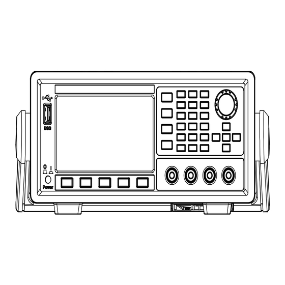
Page 10: Introduction Of Front Panel
8 Function key 9 CH1 output terminals 10 Menu key 11 Power switch 1.3 Introduction of Keyboard The functions of keys on the front panel of the IT6412 power supply are shown in the following table. Key tag Name and function Home Home key, used for canceling the present interface and switching to the Source interface. -
Page 11: Introduction Of Interface Display Information
1.4 Introduction of Interface Display Information Home interface After IT6412 power supply is turned on, the power supply function interface is displayed as follows. Menu configuration interface Press the [Menu] soft key to enter the Menu configuration interface which comprises 7 functional icons. -
Page 12: Introduction Of Interface Symbols
System menu, comprising Sys Log, Sys Conf, Sys Info, Sys Comm, Sys Cal, etc. 1.5 Introduction of Interface Symbols The IT6412 Power Supply interface will show the following symbols and icons. Status Bar icon Status description CH1 indication: when figure 1 is lighted on, it indicates that the CH1 output is switched on;... -
Page 13: Introduction Of Rear Panel
This icon appears when the voltage loaded on the output terminal is 120% of the rated voltage. 1.6 Introduction of Rear Panel Schematic Diagram of Rear Panel of IT6412 Power Supply 1 Vent hole 2 Remote sense terminal, the output terminal and DVM terminal(CH1) -
Page 14: Chapter2 Basic Operation
Basic Operation Chapter2 Basic Operation This Chapter introduces related operations for keys on the front panel of IT6412 power supply. When the keys on the front panel are used for operation, the power supply should be under local operation mode, under which, the User can perform all functions of the power supply through the front panel keys. -
Page 15: Config Menu Function (Config)
Configuration menu setting Source Configuration Source Config Configure the output speed: Fast or Output Speed: Normal Conf1 Configure voltage output range: High Voltage Range: or Low Configure current sense: High or Current Sense: Auto Copyright © Itech Electronic Co., Ltd. - Page 16 This option is used for configuring the voltage output range: High and Low. Voltage output range Voltage range -15.1V to +15.1V 0 to +15.1V High Current output range: -3.05A to +3.05A -9.05V to +9.05V 0 to +9.05V Current output range: -5.05A to +5.05A Copyright © Itech Electronic Co., Ltd.
-
Page 17: Math Menu Function (Math)
Statistics: Mean Peak, Max and Min Buffer Statistics: Buffer Buffer control mode: Always (FIFO), Next Buffer Mode: (Repetition), Never (OFF) Automatic clear when full: ON or OFF Auto Clear: Export to the USB (BufCH1_xx.txt) Export To USB: Copyright © Itech Electronic Co., Ltd. -
Page 18: Key Lock Function
0.5A and 0.2Ω (For details, refer to 3.2 Setting of Measurement Function and Interface Display). Press the [Save] soft key to save the set parameters in the save position displayed in present Save successively. In this case, the parameters are saved in Save0. Copyright © Itech Electronic Co., Ltd. -
Page 19: Triggering Function
Press the [Ok] soft key to confirm the recalled group. Press the [Esc] soft key to return to the Power Supply Function interface. 2.9 Triggering Function IT6412 power supply can be triggered by means of: manual trigger (Internal), command trigger (BUS) and external signal trigger (External). ... -
Page 20: Protection Function
The power supply is also provided with the following protections: over voltage protection (OVP), over current protection (OCP) and over temperature protection (OTP). Configure protection function In the IT6412 power supply, the User can configure the following parameters for OVP and OCP protection functions: Protection type State... - Page 21 If the over-voltage protection is triggered, the output will immediately be switched off and the LCD display will show Copyright © Itech Electronic Co., Ltd.
-
Page 22: Digital Quantity Control Interface
OUTPut ON. 2.11 Digital Quantity Control Interface The rear panel of IT6412 power supply has a DB9 digital quantity control interface (SYSTEM I/O), which can be used for controlling and monitoring power supply output. Pins of SYSTEM I/O interface at the rear panel are defined as follows: Copyright ©... - Page 23 Press the [Esc] key to return. External On/Off control The output state of the IT6412 power supply can be controlled through external TTL level. When the external output control function is on, the On/Off on the front panel of power supply will become invalid and the power supply output state can only be controlled through external TTL.
- Page 24 Press the [Menu] key to enter the Menu Configuration page. Select “Config > Conf2” to enter to Configuration Menu interface. Select the “Digital Function” parameters by the key. Press the right soft key corresponding to this parameter to set the external digital Copyright © Itech Electronic Co., Ltd.
-
Page 25: Series Operation
For example, if you connect CH1 and CH2 of the IT6412 power supply in series, the total output is -15V~+30V (-9V~+18V)/±3A(±5A)/90W and the output power and output voltage are both double. -
Page 26: Chapter3 Power Supply Function
Power Supply Function Chapter3 Power Supply Function This chapter describes the features and use of the IT6412 power supply in details. 3.1 Basic Concepts IT6412 has common power supply function, abundant basic electric energy measurement functions for precise measurement of voltage and current as well as DVM measurement. - Page 27 Voltage effective value [V] Channel source area This area mainly displays setting values of CH1/CH2, as follows: Parameters Parameter descriptions Vset Set up voltage output Iset Set up current output Rset Set up resistance output Copyright © Itech Electronic Co., Ltd.
- Page 28 The low current value [mA] Drms DVM Measured Voltage effective value [V] DVM Function In IT6412, 2 channels are provided with one DVM (digital display voltmeter) respectively for measuring external voltages with range from -20V to +20V. Copyright © Itech Electronic Co., Ltd.
-
Page 29: Setting Of Measurement Function And Interface Display
Display The 4.3’’ colorful high-resolution TFT LCD and dual-channel function of the IT6412 power supply enable you a clear and convenient experience. IT6412 is provided with Single (Single-channel display) and Dual (Dual-channel display). The User can customize the parameter types and display sequences. -
Page 30: Setting Of Output Parameters
Iset setting place. Press the Right/Left ( ) key in the Arrow keys to select the high and low position to be slightly adjusted (black font background). Rotate the Knob to adjust the current set value. Copyright © Itech Electronic Co., Ltd. -
Page 31: Setting Of Filter
Select the parameters Sample Rate and Sample Count and directly change the values through Numeric keys or Knob. Character Function description Copyright © Itech Electronic Co., Ltd. - Page 32 (Average), Hanning filtering (Hanning) and Rectangle filtering (Rectangle). Sample Rate Set the sample rate for data buffer. Sample Count Set the sample count for data buffer. Press the [OK] key to save the setting information. Copyright © Itech Electronic Co., Ltd.
-
Page 33: Chapter4 Waveform Display Function
IT6412 power supply in details. 4.1 Basic Concepts The IT6412 power supply provides the waveform display function based on sample data. The voltage or current waveform of the input unit can be displayed or hidden on the interface, which is available for selection based on actual condition. - Page 34 Before using the trigger function, the user needs to configure the following parameters: Trigger mode The trigger mode refers to conditions for updating the contents displayed Copyright © Itech Electronic Co., Ltd.
-
Page 35: Setting Of Knob Functions
Display interface. The Knob is defaulted as adjusting grounding level of voltage channel. When the interface displays “Knob Volt”, it indicates that the Knob can adjust the grounding level of voltage channel, as follows: Copyright © Itech Electronic Co., Ltd. - Page 36 In the above interface, press the [Knob Volt] soft key. In this case, “Knob DVM” is displayed, indicating that the Knob can adjust the grounding level of DVM channel. Copyright © Itech Electronic Co., Ltd.
-
Page 37: Horizontal Control And Vertical Control
The trigger point is displayed along the top of the display grid. Adjust vertical calibration On the Waveform Display interface, press the [V_Range] or [I_Range] soft key to display the following interfaces: Copyright © Itech Electronic Co., Ltd. -
Page 38: Setting Of Trigger Configuration
On the Waveform Display interface, press the [Trig Set] soft key to enter the Trigger Setting interface, as shown below: Press the right soft key corresponding to the parameter to select the required trigger configuration. Source: Select the trigger source, voltage signal, current signal or Copyright © Itech Electronic Co., Ltd. - Page 39 When single measurement is performed under running conditions, one measurement will be performed immediately by the instrument and then the stop status will be enabled. Copyright © Itech Electronic Co., Ltd.
-
Page 40: Chapter5 Battery Simulation Function
5.1 Basic Concepts With the unique current bipolar design and 0-1Ω variable output impedance, IT6412 is applicable to types of portable battery charge-discharge tests. Simulating the battery charge-discharge features and assisting with other tests are also reliable. One equipment, diversified applications. - Page 41 On the Battery Simulation Function interface, press the [Config] soft key to enter the Stop Condition Configuration interface of battery test. Parameter Parameter description Voltage Shut(V) Configure shut-off voltage Current Shut(A) Configure shut-off current Copyright © Itech Electronic Co., Ltd.
-
Page 42: Battery Charging Function
5.2 Battery Charging Function The IT6412 power supply is provided with battery charging function. After selecting the battery charging mode (Charge), the “Charging voltage” (Vset) and charging current (Iset) under the charging mode can be set. During the charging, the voltage, current and charged capacity of the battery can be observed. -
Page 43: Battery Discharging Function
Battery Simulation Function 5.3 Battery Discharging Function The IT6412 power supply is provided with battery discharging function. After selecting the battery discharging mode (Discharge), the “Discharging voltage” (Vset) and discharging current (Iset) under the discharging mode can be set. During the discharging, the voltage, current and discharged capacity of the battery can be observed. - Page 44 Volt Configure voltage for single step Configure resistance for single step Display area of characteristic data This area mainly displays the edited battery characteristic data group. Use to roll and view this list. Copyright © Itech Electronic Co., Ltd.
- Page 45 , move the cursor to the Group setting place and press the Numeric key or Knob to set the number value. In this example, the Group number is set as 03. Configure step capacity (Capacity), step voltage (Voltage) and step Copyright © Itech Electronic Co., Ltd.
- Page 46 Press the [Insert] soft key to insert the present set value to the list as the step of the Group 03. Repeat Steps 6 - 7 to set the other 2 steps in Group 03. After editing, press the [Esc] key to return. Copyright © Itech Electronic Co., Ltd.
- Page 47 Battery Simulation Function Import the external battery characteristic data The IT6412 can import the external battery characteristic data and recall it at simulation operation. Operating procedures are as below: Create a new Excel document on local PC and name it BATTERYCH1.csv.
- Page 48 Numeric key or Knob to set the number value of the data group to be recalled. Press the [OK] key for confirmation. At this time, the characteristic data display area displays the characteristic data of each step in this group. Copyright © Itech Electronic Co., Ltd.
- Page 49 External import: Insert the USB (containing BATTERYCH1.csv document) to the USB interface on the front panel of power supply. The IT6412 automatically detects and imports the BATTERYCH1.csv document. Internal recall: Select the data group in which recall is required based on the above steps in “Edit the battery characteristic data”...
- Page 50 You can press [Stop] to pause the test during the battery simulation test. And press [Capacity Clear] to restart the test. Copyright © Itech Electronic Co., Ltd.
-
Page 51: Chapter6 List Function
List Function Chapter6 List Function This chapter describes the features and use of the List function of the IT6412 power supply in details. 6.1 Basic Concepts The User can edit the test procedures composed of several steps through the List function. There are 20 Lists (List 0 to List 19) under the List function for selection, which can be controlled through the Select parameters on the interface. - Page 52 List List sequence Cycle Cycle times (0-19) Total Total number Vset Configure step steps (0-29) voltage Iset Configure step Rset Configure step current resistance Dwell Configure step time - List display area Copyright © Itech Electronic Co., Ltd.
-
Page 53: List Operation
Numeric key or Knob to set the number value. In this example, the List number is set as 02. Use the key to adjust the cursor position and set the values of Cycle, Vset, Iset, Rset and Dwell. Copyright © Itech Electronic Co., Ltd. - Page 54 The User can repeat the above steps to edit other Lists. In this example, edit the List 03 in CH1. External import of List The IT6412 power supply is provided with external import of List documents. Copyright © Itech Electronic Co., Ltd.
- Page 55 If several Lists are edited, the User may select the required ones. Operating procedures are as below: Press the [Sequence Sel] soft key to enter the Sequence Selection interface. The User can select the active List on this interface. Copyright © Itech Electronic Co., Ltd.
- Page 56 [Trig] key will be switched among 1/2/All one by one. On the Sequence Selection and Configuration interface, press the [OFF CH1] soft key to configure the List status as ON and switch on the List function. Copyright © Itech Electronic Co., Ltd.
- Page 57 Press the [Sequence Sel] soft key on the List interface to enter the Sequence Configuration interface. Press the [ON CH1] soft key to set the List status as OFF. And the instrument will exit the List operation mode. Copyright © Itech Electronic Co., Ltd.
-
Page 58: Chapter7 Routine Maintenance
Chapter 3 “Inspecting the Instrument” of IT6412 Installation Guide for detailed steps of self-inspection. 7.2 Error Information References This section describes all error information of the IT6412 power as well as error causes and disposals. All prompt information is listed. Prompt message list... -
Page 59: Contact Of Itech Engineers
Collect the SN number ITECH will constantly improve the product performance, availability and reliability. The service personnel of ITECH will record changes of each instrument. All relevant information is marked uniquely according to the serial number of each instrument. The equipment returned for repair must adopt the SN number as the tracking ID. -
Page 60: Returning Your Power For Service
Calibration Interval ITECH suggests that the IT6412 power calibration frequency is 1 time/year. 7.5 Returning Your Power for Service When you want to return your power to ITECH company, please read the following information. Package the power supply for Shipment When instruments are required for factory maintenance, please refer to the following steps to pack the instruments which need to send out. - Page 61 Routine Maintenance Please pay attention to read the document preface about warranty service delivery cost in the relevant specification with the delivery. Copyright © Itech Electronic Co., Ltd.
-
Page 62: Chapter8 Technical Specification
≤150uS Fast mode Full-load) Set output off (*2) (*6) ≤150uS Fast mode ( ) Rise time Full-load Current ≤10mS Normal mode Transient Response ≤50uS Recovered to 50 mV Time 50%-100% Load Fast mode change Copyright © Itech Electronic Co., Ltd. - Page 63 Common-mode voltage rejection 4.3MΩ ± 1% Input impedance (*1) Maximum error of OVP precision at power supply terminal under full load. (*2) The output polarity is unchanged, the time that the power output value Copyright © Itech Electronic Co., Ltd.
- Page 64 (*4) The current readback accuracy of the 5mA Range is measured under constant voltage mode. (*5) The CH2 doesn’t support Relay off function. (*6) Set output off. *The above specifications may be subject to change without prior notice. Copyright © Itech Electronic Co., Ltd.
-
Page 65: Chapter9 Remote Operation Mode
Remote Operation Mode Chapter9 Remote Operation Mode IT6412 power supply is provided with three communication interfaces to communicate with a computer for selection, including USB, LAN and GPIB. 9.1 USB Interface Use cables with double USB interface to connect power and PC. All power functions are programmable over the USB. -
Page 66: Appendix
Specifications of Red and Black Test Lines ITECH provides you with optional red and black test lines, which individual sales and you can select for test. For specifications of ITECH test lines and maximum current values, refer to the table below. - Page 67 Contact US Thank you for purchasing ITECH products. If you have any doubt about this product, please contact us as follow. 1. Please refer to the CD-ROM of related user’s manual in package. 2. Visit ITECH website www.itechate.com . 3. Select the most convenient contact for further consultation.
Need help?
Do you have a question about the IT6412 and is the answer not in the manual?
Questions and answers