Table of Contents
Advertisement
Varispeed AC
INSTRUCTION MANUAL
Matrix Converter for Environmentally Friendly Motor Drives
Model : CIMR-ACA
200V Class 5.5 to 45kW ( 9 to 63kVA)
400V Class 5.5 to 75kW (10 to 114kVA)
Upon receipt of the product and prior to initial operation, read these instructions
thoroughly, and retain for future reference.
YASKAWA
YASKAWA
MANUAL NO. TOEP C710636 00D
Advertisement
Table of Contents
Troubleshooting

Related Manuals for YASKAWA CIMR-ACA4011


Summary of Contents for YASKAWA CIMR-ACA4011
- Page 1 YASKAWA Varispeed AC INSTRUCTION MANUAL Matrix Converter for Environmentally Friendly Motor Drives Model : CIMR-ACA 200V Class 5.5 to 45kW ( 9 to 63kVA) 400V Class 5.5 to 75kW (10 to 114kVA) Upon receipt of the product and prior to initial operation, read these instructions thoroughly, and retain for future reference.
- Page 2 Yaskawa. No patent liability is assumed with respect to the use of the information contained herein. Moreover, because Yaskawa is con- stantly striving to improve its high-quality products, the information contained in this manual is subject to change without notice.
- Page 3 • To order a new copy of this manual, contact your Yaskawa representatives or the nearest Yaskawa sales office and provide the manual number shown on the front cover.
-
Page 4: Safety Information
Safety Information The symbols below appear throughout this manual to provide precautions and warnings. Failure to heed the precautions listed in these pages can result in damage to the product or other devices, even serious or fatal injury. “WARNING” indicates a safety concern that if not heeded, could possibly result in serious injury or loss of life. -
Page 5: Safety Precautions
Safety Precautions Confirmations upon Delivery CAUTION • Never install an MxC that is damaged or has missing components. Failure to do so may result in injury. Installation CAUTION • Always hold the case when carrying the MxC. If the MxC is held by the front cover, the main body of the MxC may fall, possibly resulting in injury. •... - Page 6 CAUTION • Be sure that the ground terminal is properly grounded using a wire of the recommended size. 200 V class: Ground to 100 Ω or less 400 V class: Ground to 10 Ω or less If a wire smaller than the recommended size is used, the MxC may not operate properly. •...
- Page 7 CAUTION • Do not touch the cooling fins (heatsink), braking resistor, or Braking Resistor Unit. These compo- nents can become extremely hot. These components become hot enough to cause serious burns. • Be sure that the motor and machine is within the applicable ranges before starting operation. Failure to do so may result in injury.
- Page 8 Failure to do so may result in injury or electric shock. CAUTION • Contact your Yaskawa representative if you intend to use the MxC with a non-Yaskawa motor or any other motor not listed in Yaskawa product literature. The MxC can be used with three-phase induction motors with 2, 4, or 6 poles. A multi-pole motor with 8 poles or more, a PM motor, or a motor designed for use with machine tools cannot be used with the MxC.
-
Page 9: Location Of Warning Information
Warning information is printed on the MxC as indicated in the following illustration. Obey all warnings to prevent damage and injury. Warning information position Illustration shows a CIMR-ACA4011 Warning Information Read this manual before installing the MxC. WARNING Risk of electric shock. -
Page 10: Warranty Information
Periodic inspections must be conducted by the customer. However, upon request, someone from Yaskawa or one of Yaskawa’s Service Centers can inspect the product for a fee. In this case, if after conferring with the customer, a Yaskawa product is found to be defective due to Yaskawa workmanship or materials and the defect occurs during the warranty period, then this fee will be waived and the problem remedied free of charge. -
Page 11: Registered Trademarks
Registered Trademarks The following registered trademarks are used in this manual: CC-Link is a registered trademark of CC-Link Partner Association. • DeviceNet is a registered trademark of ODVA (Open DeviceNet Vendors Association, Inc.). • CANopen is a registered trademark of CiA (CAN in Automation). •... -
Page 12: Table Of Contents
Contents Safety Information ......................ii Safety Precautions ......................iii Location of Warning Information ..................vii Warranty Information ...................... viii Registered Trademarks ....................ix MxC Physical Installation ............1-1 MxC Introduction ..................1-2 Introducing the MxC ....................... 1-2 MxC Models ........................1-3 Confirmations upon Delivery ................ 1-4 Checks ........................... - Page 13 Control Circuit Terminal Connections ................2-23 Control Circuit Wiring Precautions................2-24 Wiring Check ....................2-25 Checks..........................2-25 Installing and Wiring Option Cards .............2-26 Option Card Models and Specifications................2-26 Installation........................2-27 PG Speed Control Card Terminals and Specifications..........2-28 Wiring..........................2-30 Wiring Terminal Blocks ....................2-32 Selecting the Number of PG (Encoder) Pulses ............2-33 Digital Operator and Modes...........
- Page 14 Quick Programming Mode and Available Parameters ........... 5-4 Parameter Tables ..................5-7 A: Initialization ........................ 5-7 b: Application........................5-9 C: Auto-Tuning ......................5-16 d: Reference......................... 5-20 E: Motor Parameter ...................... 5-25 F: Option........................5-29 H: Terminal Function ....................5-34 L: Protection Function ....................5-43 n: Special Adjustments ....................
- Page 15 Stabilizing Speed (Speed Feedback Detection Function) ..........6-37 Machine Protection..................6-38 Reducing Noise and Leakage Current................6-38 Limiting Motor Torque (Torque Limit Function).............6-40 Stall Prevention during Run ..................6-43 Changing Stall Prevention Level during Run Using an Analog Input......6-44 Using Frequency Detection: L4-01 to L4-05 ..............6-44 Detecting Motor Torque ....................
- Page 16 Increasing the Speed Reference Response (Feed Forward Control) ......6-120 Droop Control Function ....................6-121 Zero-Servo Function....................6-123 Digital Operator Functions................ 6-125 Setting Digital Operator Functions ................6-125 Copying Parameters....................6-128 Writing Parameters from the Digital Operator ............6-133 Setting a Password ....................6-133 Displaying User-Set Parameters Only................
- Page 17 Settings......................... 10-8 Handling........................10-8 Motor Application Precautions..............10-10 Using the MxC to Run an Existing Standard Motor ............ 10-10 Using the MxC for Motors other than Standard Yaskawa Motors ....... 10-11 Power Transmission Mechanism (Speed Reducers, Belts, and Chains)....10-11 Wiring Examples..................10-12...
- Page 18 Using a VS Operator ....................10-12 Using Transistors for Input Signals and a 0 V Common in Sinking Mode with an Internal Power Supply ......................10-13 Using Transistors for Input Signals and a +24 V Common in Sourcing Mode ... 10-14 Using Transistors for Input Signals and a 0 V Common in Sink Mode with an External Power Supply ......................
-
Page 19: Mxc Physical Installation
MxC Physical Installation This chapter describes the requirements for receiving and installing the MxC. MxC Introduction............1-2 Confirmations upon Delivery.........1-4 Exterior and Mounting Dimensions.......1-7 Checking and Controlling the Installation Site ....1-9 Installation Orientation and Clearance......1-10 Removing and Attaching the Terminal Cover ..... 1-11 Removing/Attaching the Digital Operator and Front Cover ................1-12... -
Page 20: Mxc Introduction
MxC Introduction Introducing the MxC The design of the MxC is simpler and more efficient than a conventional inverter. The MxC uses a different mechanism to generate AC voltage, and relies on nine bi-directional switches to adjust AC output power to the motor directly from an AC line power input. -
Page 21: Mxc Models
[IEC IP20, NEMA 1 (Type 1)] CIMR-ACA CIMR-ACA CIMR-ACA25P5 25P50 25P51 CIMR-ACA2011 20110 20111 200 V class CIMR-ACA2022 20220 20221 CIMR-ACA2045 20450 20451 CIMR-ACA45P5 45P50 45P51 CIMR-ACA4011 40110 40111 CIMR-ACA4022 40220 40221 400 V class CIMR-ACA4045 40450 40451 CIMR-ACA4075 40750 40750 * Under development. -
Page 22: Confirmations Upon Delivery
If you find any irregularities with the items listed above, contact the agency from which the MxC was pur- chased, or your Yaskawa representative immediately. Nameplate Information An information nameplate appears on the right side of each MxC. The nameplate shows the model number, specifications, lot number, serial number, and other information on the MxC. - Page 23 Confirmations upon Delivery MxC Model Numbers The model number of the MxC on the nameplate indicates the specification, voltage class, and maximum motor capacity of the MxC in alphanumeric code. CIMR - AC A 4 011 Specification Max. Motor Capacity Standard model 5.5 kW 11 kW...
-
Page 24: Component Names
The exterior of the MxC and its components are shown in Fig 1.4. Fig 1.5 shows the MxC with the terminal cover removed. Mounting holes Front cover Cooling fan Controller cover Digital operator Terminal cover Nameplate Fig 1.4 MxC Exterior (Model: CIMR-ACA4011) Charge indicator Control circuit terminals Main circuit terminals Ground terminal Fig 1.5 Terminal Arrangement (Model: CIMR-ACA4011) -
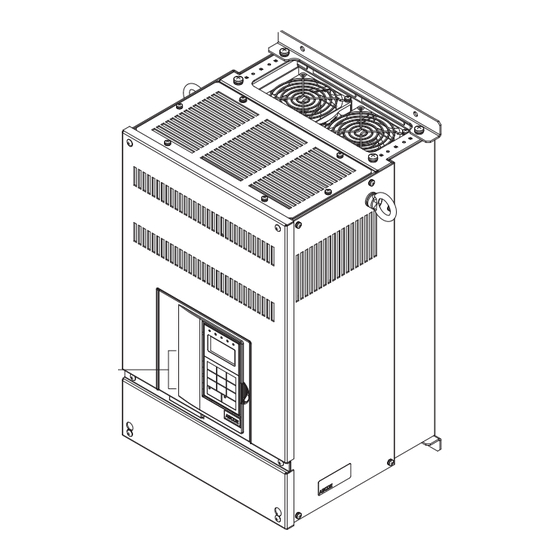
Page 25: Exterior And Mounting Dimensions
Exterior and Mounting Dimensions Exterior and Mounting Dimensions Figure 1.6 shows the exterior of the open-chassis type (IP00). Fig 1.6 Exterior of Open Chassis MxCs Table 1.3 Dimensions (mm) and Approx Weight (kg) of MxC Dimensions (mm) Approx. Cool- Voltage Max Applicable Weight Class... - Page 26 Table 1.4 External Dimensions (mm) and Approx Weight (kg) of MxCs External Dimensions (mm) Approx. Voltage Max Applicable Cooling Weight Class Motor Output (kW) Method (kg) 200 V (3-phase) 1272 400 V (3-phase) 1272 1272 * Under development.
-
Page 27: Checking And Controlling The Installation Site
Checking and Controlling the Installation Site Checking and Controlling the Installation Site The MxC must be installed and used in an area that complies with the conditions listed below. Maintain the conditions of the area for proper performance life. Installation Site Install the MxC under the following conditions, making sure that the area complies with Pollution Level 2 or less (as defined by UL standards). -
Page 28: Installation Orientation And Clearance
Installation Orientation and Clearance Install the MxC vertically so as not to reduce the cooling effect. When installing the MxC, always provide the following installation space to allow normal heat dissipation. 50 mm min. 120 mm min. 50 mm min. min. -
Page 29: Removing And Attaching The Terminal Cover
1 and then lift up on the terminal in the direction of arrow 2. Note: For 45 kW and 75 kW MxCs, an additional screw is located in position A as indicated below. Fig 1.9 Removing the Terminal Cover (Model: CIMR-ACA4011) Attaching the Terminal Cover Once wiring the terminal block has been completed, attach the terminal cover by reversing the removal proce- dure. -
Page 30: Removing/Attaching The Digital Operator And
2 to remove the digital operator as shown in the following illustration. Fig 1.10 Removing the Digital Operator (Model: CIMR-ACA4011) Removing the Front Cover Pull the bottom of the front cover in the direction as shown by arrow 2 while pushing both sides of the cover in the direction shown by arrow 1. - Page 31 1. Hook the digital operator at point A (two locations) on the front cover in the direction of arrow 1 as shown in the illustration below. 2. Press the digital operator in the direction of arrow 2 until it snaps in place at B (two locations). Fig 1.12 Mounting the Digital Operator (Model: CIMR-ACA4011)
-
Page 32: Wiring
Wiring This chapter describes wiring terminals, main circuit terminal connections, main circuit termi- nal wiring specifications, control circuit terminals, and control circuit wiring specifications. Connecting Peripheral Devices ........2-2 Connection Diagram .............2-3 Terminal Block Configuration ........2-5 Wiring Main Circuit Terminals ........2-6 Wiring Control Circuit Terminals .........2-16 Wiring Check ..............2-24 Installing and Wiring Option Cards ......2-25... -
Page 33: Connecting Peripheral Devices
Connecting Peripheral Devices Examples of connections between the MxC and typical peripheral devices are shown in Fig 2.1. Power supply Molded-case circuit breaker or ground fault interrupter Magnetic contactor (MC) Input noise filter Zero-phase reactor Ground Output noise filter Zero-phase reactor Motor Ground Fig 2.1 Example Connections to Peripheral Devices... -
Page 34: Connection Diagram
Connection Diagram Connection Diagram The connection diagram of the MxC is shown in Fig 2.2. When using the digital operator, the motor can be operated by wiring only the main circuits. Motor 2MCCB Cooling fan 1MCCB R/L1 U/T1 3-phase power CIMR-ACA2011 200 V to 220 V S/L2... - Page 35 1. Control circuit terminals are arranged as shown below. IMPORTANT 2. The output current capacity of the +V terminal is 20 mA. Do not create a short between the +V, -V, and AC control-circuit terminals. This may cause the MxC to fault out or malfunction. 3.
-
Page 36: Terminal Block Configuration
MxCs, Fig. 2.4 for a 22 kW MxC, and Fig.2.5 for 45 kW and 75 kW MxCs. Charge indicator Control circuit terminals Main circuit terminals Ground terminal Fig 2.3 Terminal Arrangement (Model: CIMR-ACA4011) Charge indicator Control circuit terminals Main circuit terminals Ground terminal Fig 2.4 Terminal Arrangement (Model: CIMR-ACA4022) -
Page 37: Wiring Main Circuit Terminals
Wiring Main Circuit Terminals Applicable Wire Gauges and Closed-Loop Connectors Select the appropriate wires and crimp terminals listed in Table 2.1 through Table 2.3. Table 2.1 200 V Class Wire Gauges Possible Recom- Tightening Wire MxC Model mended Terminal Terminal Symbol Torque Wire Type Gauges... - Page 38 Wiring Main Circuit Terminals Table 2.2 400 V Class Wire Gauges Possible Recom- Tightening Wire MxC Model mended Terminal Terminal Symbol Torque Wire Type Gauges Wire Gauge CIMR- Screws (N•m) (AWG) (AWG) 3.5 to 14 R/L1, S/L2, T/L3, U/T1, V/T2, W/T3 2 to 2.4 Nm (12 to 6) (12)
- Page 39 Table 2.3 Closed-Loop Connector Sizes (JIS C2805) (200 V class and 400 V class) Terminal Screws Size Wire Thickness (mm M3.5 1.25 to 3.5 1.25 to 4 M3.5 1.25 to 3.5 0.75 1.25 to 4 M3.5 1.25 to 3.5 1.25 1.25 to 4 M3.5 2 to 3.5...
-
Page 40: Main Circuit Terminal Functions
Wiring Main Circuit Terminals Main Circuit Terminal Functions Main circuit terminal functions are summarized according to terminal symbols in Table 2.4. Wire the terminals correctly for the desired purpose. Table 2.4 Main Circuit Terminal Functions (200 V class and 400 V class) Purpose Terminal symbols Main circuit power input... -
Page 41: Standard Connection Diagrams
Standard Connection Diagrams Standard MxC connection diagrams are shown in Fig 2.7. These are the same for both 200 V class and 400 V class MxCs. The connections depend on the MxC capacity. CIMR-ACA25P5 to 2045, 45P5 to 4075 ∗1 ∗1 ∗2 ∗2... -
Page 42: Input And Output Wiring In The Main Circuit
Wiring Main Circuit Terminals Input and Output Wiring in the Main Circuit This section describes wiring connections for the main circuit inputs and outputs. Wiring Main Circuit Inputs Observe the following precautions when wiring inputs for the main circuit power supply. Installing a Molded-Case Circuit Breaker Always connect the power input terminals (R, S, and T) and power supply via a molded-case circuit breaker (MCCB) suitable for the MxC. - Page 43 Installing a Magnetic Contactor If the power supply for the main circuit gets shut off during a sequence, a magnetic contactor can be used to stop the MxC. When a magnetic contactor is installed on the primary side of the main circuit to forcibly stop the MxC, regenerative braking does not work and the MxC will simply coast freely until it stops.
- Page 44 Wiring Main Circuit Terminals Wiring the Output Side of the Main Circuit Observe the following precautions when wiring the main output circuits. Connecting the MxC and Motor Connect output terminals U, V, and W to motor lead wires U, V, and W, respectively. Make sure the motor rotates forward when the Forward Run Command is given.
- Page 45 Preventing Inductive Noise As described previously, a noise filter can be used to prevent inductive noise from being generated on the out- put side. Alternatively, cables can be routed through a grounded metal pipe to prevent inductive noise. Keep- ing the metal pipe at least 30 cm away from the signal line considerably reduces inductive noise. Power Metal pipe supply...
- Page 46 Wiring Main Circuit Terminals Ground Wiring Observe the following precautions when grounding the MxC. Always use the ground terminal of the 200 V MxC with a ground resistance of less than 100 Ω and that of • the 400 V MxC with a ground resistance of less than 10 Ω. Do not share the ground wire with other devices, such as welding machines or power tools.
-
Page 47: Wiring Control Circuit Terminals
* 2. Refer to Table 2.3 Closed-Loop Connector Sizes (JIS C2805) (200 V class and 400 V class) for suitable closed-loop crimp terminal sizes for the wires. * 3. Yaskawa recommends using a straight solderless terminal on signal lines to simplify wiring and improve reliability. - Page 48 Wiring Control Circuit Terminals Straight Solderless Terminals for Signal Lines Models and sizes of straight solderless terminals are shown in the following table. Table 2.7 Straight Solderless Terminal Sizes Wire Gauge mm Model Manufacturer (AWG) 0.25 (24) AI 0.25 - 8YE 12.5 0.5 (20) AI 0.5 - 8WH...
-
Page 49: Control Circuit Terminal Functions
Control Circuit Terminal Functions The functions available by using the control circuit terminals are shown in Table 2.8. Use the appropriate ter- minals for the correct purposes. Table 2.8 Control Circuit Terminals Signal Name Function Signal Level Type Forward Run/Stop Command Forward run when on, stopped when off. Reverse Run/Stop Command Reverse run when on, stopped when off. - Page 50 Wiring Control Circuit Terminals Table 2.8 Control Circuit Terminals (Continued) Signal Name Function Signal Level Type Multi-Function PHC Output Default: Zero-speed Zero-speed level (b2-01) or below when on. Default: Frequency agreement detection Multi-Function PHC Output Frequency within 2 Hz of set frequency when on.
- Page 51 Shunt Connector CN5 and DIP Switch S1 The shunt connector CN 5 and DIP switch S1 are described in this section. Terminating resistance Analog input switch : Default Note: Refer to Table 2.9 for S1 functions and to Table 2.10 for CN5 functions.
- Page 52 Wiring Control Circuit Terminals Sinking/Sourcing Mode The input terminal logic can be switched between Sinking Mode (0 V common) and Sourcing Mode (+24 V common) if shunt connector CN5 is used. An external 24 V power supply is also supported, providing more freedom in signal input methods.
-
Page 53: Control Circuit Terminal Connections
Control Circuit Terminal Connections Connections to MxC control circuit terminals are shown in Fig 2.20. CIMR-ACA2011 Forward Run/Stop Reverse Run/Stop External fault Fault reset Multi-step speed reference 1 (Main speed switching) Multi-step speed reference 2 Jog frequency selection Multi-function contact inputs External baseblock (Default) -
Page 54: Control Circuit Wiring Precautions
Wiring Control Circuit Terminals Control Circuit Wiring Precautions Observe the following precautions when wiring control circuits. Separate control circuit wiring from main circuit wiring (terminals R/L1, S/L2, T/L3, U/T1, V/T2, W/T3, • r2, s2, t2, p1, and n1) and other high-power lines. Separate wiring for control circuit terminals MA, MB, MC, M1, and M2 (contact outputs) from wiring to •... -
Page 55: Wiring Check
Wiring Check Checks Check all connections after wiring has been completed. Do not perform a buzzer check on control circuits. Use the following checklist: Is all wiring correct? • Make sure all wire clippings, screws, and other foreign material has been removed from the MxC. •... -
Page 56: Installing And Wiring Option Cards
Installing and Wiring Option Cards Installing and Wiring Option Cards Option Card Models and Specifications Up to three option cards can be mounted in the MxC. An option card can be mounted into each of the three slots available on the control board (A, C, and D) shown in Fig 2.22. Table 2.11 lists the type of option cards available and their specifications. -
Page 57: Installation
Installation Before mounting an option card, remove the terminal cover and be sure that the charge LED inside the MxC has gone out. After confirming that the charge indicator is no longer lit, remove the digital operator and front cover, and then mount the option card. Refer to documentation provided with the option card for mounting instructions for option slots A, C, and D. -
Page 58: Pg Speed Control Card Terminals And Specifications
Installing and Wiring Option Cards PG Speed Control Card Terminals and Specifications The terminal specifications for the PG Speed Control Cards are given in the following tables. PG-B2 The terminal specifications for the PG-B2 are given in the following table. Table 2.12 PG-B2 Terminal Specifications Terminal Contents... - Page 59 PG-X2 The terminal specifications for the PG-X2 are given in the following table. Table 2.13 PG-X2 Terminal Specifications Terminal Contents Specifications 12 VDC (±5%), 200 mA max* Power supply for pulse generator 0 VDC (ground for power supply) 5 VDC (±5%), 200 mA max* A-phase + input terminal A-phase - input terminal B-phase + input terminal...
-
Page 60: Wiring
Installing and Wiring Option Cards Wiring Wiring examples are provided in the following illustrations for the option cards. Wiring the PG-B2 Wiring examples for the PG-B2 are provided in the following illustrations. Three-phase 200 VAC (400 VAC) R/L1 U/T1 S/L2 V/T2 R/L3 W/T3... - Page 61 Wiring the PG-X2 Wiring examples for the PG-X2 are provided in the following illustrations. Three-phase 200 VAC (400 VAC) R/L1 U/T1 S/L2 V/T2 T/L3 W/T3 PG-X2 Power supply +12 V Power supply 0 V Power supply +5 V A-phase pulse input (+) A-phase pulse input (-) B-phase pulse input (+) B-phase pulse input (-)
-
Page 62: Wiring Terminal Blocks
0.5 to 2 equivalent) Straight Solderless Terminals for Control Circuit Terminals Yaskawa recommends using straight solderless terminal on signal lines to simplify wiring and improve reli- ability. Refer to Straight Solderless Terminal Sizes for specifications. Closed-Loop Connector Sizes and Tightening Torque The closed-loop connectors and tightening torques for various wire gauges are shown in Table 2.15. -
Page 63: Selecting The Number Of Pg (Encoder) Pulses
Selecting the Number of PG (Encoder) Pulses The setting for the number of PG pulses depends on the model of PG Speed Control Card being used. Set the correct number for your model. PG-B2 The maximum response frequency is 32,767 Hz. Use a PG that outputs a maximum frequency of approximately 20 kHz for the rotational speed of the motor. - Page 64 Installing and Wiring Option Cards PG-X2 There are 5 V and 12 V PG power supplies. Check the PG power supply specifications before connecting. The maximum response frequency is 300 kHz. Use the following equation to calculate the output frequency of the PG (f −1 Motor speed at maximum frequency output (min ×...
-
Page 65: Digital Operator And Modes
Digital Operator and Modes This chapter describes the various displays screens and functions of the digital operator keypad. An overview of the operating modes is also provided, as well as how to switch between those modes. Digital Operator.............3-2 Operation Modes ............3-5... -
Page 66: Digital Operator
Digital Operator This section describes the displays and functions of the digital operator. Overview of the Digital Operator The digital operator key names and functions are described below. Drive Mode Indicators FWD: Lit when there is a Forward Run Command input. REV: Lit when there is a Reverse Run Command input. - Page 67 Digital Operator Table 3.1 Key Functions (Continued) Name Function Selects the rotation direction of the motor when the MxC is being FWD/REV key operated from the digital operator. Selects the digit to be changed when editing parameter settings. The Right arrow/RESET key selected digit will flash.
- Page 68 The following table shows the relationship between the indicators on the RUN and STOP keys as well as the MxC operation status. The LED indicators can be on, off, or flash to indicate the operating status. Table 3.2 Relation of MxC to RUN and STOP LED Indicators STOP Priority Conditions...
-
Page 69: Operation Modes
Operation Modes Operation Modes This section describes the operation modes available in the MxC, and how to switch between modes. MxC Modes Parameters and monitoring functions in the MxC are organized into groups called “modes”. These modes make it easier to read and set parameters. Their are five separate modes available in the MxC. The five modes and their primary functions are shown in the Table 3.3. -
Page 70: Switching Between Modes
Switching Between Modes The mode selection display will appear when the MENU key is pressed from a monitor or setting display. Press the MENU key from the mode selection display to switch between the modes. Press the DATA/ENTER key from the mode selection key to monitor data and from a monitor display to access the setting display. -
Page 71: Drive Mode
Operation Modes Drive Mode Once in the Drive Mode, the user can now instruct the MxC to begin operating the motor. The following mon- itor displays can be viewed while in the Drive Mode: frequency reference, output frequency, output current, output voltage, as well as fault information and the fault history. - Page 72 Note: When changing the display with the up arrow and down arrow keys, the next display after the one for the last parameter number will be the one for the first parameter number. For example, if the up arrow key is pressed when U1-01 is displayed, the last parameter will be displayed instead of U1-02. This is indicated in the figures by the letters A and B and the numbers 1 to 6.
-
Page 73: Quick Programming Mode
Operation Modes Quick Programming Mode In the Quick Programming Mode, the user can set the basic parameters required to test run the MxC. Parameters can be changed from the setting display screen. Use the up arrow, down arrow, and right arrow keys to change parameter settings. -
Page 74: Advanced Programming Mode
Advanced Programming Mode In the Advanced Programming Mode, the user can access all MxC parameters to change settings or simply monitor performance. The user can change the setting values saved to each parameter. For example, the user can adjust the frequency the motor is running at by using the arrow keys on the keypad. - Page 75 Operation Modes Setting Parameters The procedure described below explains how to change C1-01 (Acceleration Time 1) from 10 s to 20 s. Table 3.4 Changing Parameter Settings in the Advanced Programming Mode Step Digital Operator Display Description -DRIVE- Frequency Ref First make sure that the MxC has been powered up.
- Page 76 External Fault Setting Procedure The following diagram shows how to set one of the multi-function contact inputs to be triggered when an external fault is detected. To make the setting changes, the MxC must be in the Advanced Programming Mode. Mode selection display Monitor display Setting display...
-
Page 77: Verify Mode
Operation Modes Verify Mode The Verify Mode displays any parameters that have been changed from their default settings. This includes all parameters that were changed by the user in the Programming Mode, and all parameters that were changed when Auto-Tuning was performed. If no parameter settings have been changed, then the Verify Mode display window will read, “None”. -
Page 78: Auto-Tuning Mode
Ideally, perform Auto-Tuning with the motor uncoupled from the load. When the motor cannot be disconnected from the load, perform static or terminal resistance Auto-Tuning. To set motor parameters manually, contact your Yaskawa representative. Follow the key operations in Fig 3.9 to access the Auto-Tuning Menu. - Page 79 Operation Modes Executing Auto-Tuning Set the motor output power (kW), rated voltage, rated current, rated frequency, rated speed, and number of poles as specified on the motor nameplate. Next, press RUN. The motor will begin to rotate, and the MxC will automatically set motor parameters based on the information provided from the nameplate and measurements taken during the Auto-Tuning process.
-
Page 80: Test Run
Test Run This chapter describes the procedures for Test Run of the MxC and provides an example of Test Run. Test Run Procedure ............4-2 Test Run Procedures ............4-3 Notes on Tuning the MxC ...........4-14... -
Page 81: Test Run Procedure
Test Run Procedure Test run the MxC as shown in the flowchart below: START Installation Wiring Turn on power. Confirm status. Basic settings (Quick Programming Mode) Select operating method. Vector (A1-02 = 2 or 3) *2 V/f Control? (A1-02 = 0) Set E1-03. -
Page 82: Test Run Procedures
If connecting an MxC to a power supply with high impedance, such as a Slidax, the power-supply voltage may rise during regeneration. Contact your Yaskawa representative for details. Use a power supply with a capacity that is the same or greater than the MxC capacity. -
Page 83: Basic Settings
Basic Settings Switch to the Quick Programming Mode (“QUICK” will be displayed on the LCD screen), and then set the following parameters. Refer to Chapter 3 Digital Operator and Modes for digital operator operating proce- dures and to Chapter 5 Parameters and Chapter 6 Parameter Settings by Function for details on the Parame- ters. - Page 84 Test Run Procedures Table 4.1 Parameters that Must Be Set (Continued) Parameter Setting Name Description Default Page Number Range Setting for general- Sets the motor nameplate full load current in 10% to 200% purpose 5-26 Motor Rated Cur- E2-01 amperes (A). This value is automatically set of MxC's rated motor of 6-51...
-
Page 85: Settings For The Control Methods
Settings for the Control Methods Auto-Tuning methods depend on the control method set for the MxC. Make the settings required by the con- trol method. Overview of Settings Make the required settings in the Quick Programming Mode and Auto-Tuning Mode according to the follow- ing flowchart. - Page 86 Test Run Procedures Setting the Control Method Any of the following three control methods can be set. Parameter Control Method Basic Control Main Applications Setting V/f Control A1-02 = 0 Voltage/frequency ratio fixed control Variable speed control Variable speed control, applications Open Loop Vector A1-02 = 2 Current vector control without a PG...
-
Page 87: Auto-Tuning
Auto-Tuning Use the following procedure to perform Auto-Tuning if using the vector control method or when using a long motor cable. Auto-Tuning calculates the motor characteristics and automatically sets all necessary motor parameters. If the control method was changed after Auto-Tuning, be sure to perform Auto-Tuning again. The following types of Auto-Tuning are possible in the MxC: Rotational Auto-Tuning •... - Page 88 Auto-Tuning, the value of T1-09 will be written in E1-03. When not setting T1-09, the no-load current value of Yaskawa standard motor will be written in E1-03. 1. Power will be supplied to the motor when Stationary Auto-Tuning 2 is performed even though the motor will not turn.
- Page 89 After having completed Auto-Tuning, set E1-04 (Motor Maximum Frequency) to the base frequency shown on the motor nameplate. Output voltage Rated voltage from motor nameplate T1-03 Output frequency Base frequency Base frequency from motor nameplate ×T1-03 from motor nameplate Rated voltage from motor nameplate Fig 4.3 Motor Base Frequency and MxC Input Voltage Setting 1.
- Page 90 Test Run Procedures Parameter Settings for Auto-Tuning The following parameters must be set before Auto-Tuning. Table 4.2 Parameter Settings before Auto-Tuning Data Displays during Auto-Tuning Parameter Setting Name Display Default Open Range Number Flux Loop Vector Vector Selects which set of motor parameters are to be used and set during Auto-Tuning.
-
Page 91: Application Settings
* 7. The default depends on the MxC capacity. The values for a 200 V class MxC for 5.5 kW are given. * 8. The setting range depends on the MxC capacity. The value for a 200 V class MxC for 5.5 kW is given. * 9. -
Page 92: Saving Parameters
Test Run Procedures Operation using the Digital Operator Use the digital operator to start operation in Local Mode in the same way as in no-load operation. • If a fault occurs during run, make sure the STOP key on the digital operator is easily accessible. •... -
Page 93: Notes On Tuning The Mxc
Notes on Tuning the MxC If hunting, oscillation, or other problems originating in the control system occur during Test Run, adjust the parameters listed in the following table according to the control method. This table lists only the most commonly used parameters. Table 4.3 Adjusted Parameters Recom- Control... - Page 94 Notes on Tuning the MxC Table 4.3 Adjusted Parameters (Continued) Recom- Control Parameters Performance Default mended Adjustment Method Method Setting Open loop • Increase the setting if vector Slip Compensation • Improving speed speed response is slow. 0.5 to 1.5 control Gain (C3-01) accuracy...
- Page 95 Name Parameter Setting example if low torque Setting Range Default Number near 12 Hz Display Maximum Output Frequency 200.0 (VMAX) E1-05 0.0 to 255.0 *1 *2 Max Frequency Base Frequency (FA) E1-06 0.0 to 120.0 60.0 Hz Base Frequency Mid Output Frequency (FB) E1-07 0.0 to 120.0 3.0 Hz...
- Page 96 Notes on Tuning the MxC Precautions While Tuning the MxC Do not change the Torque Compensation Gain (C4-01) from its default setting of 1.00 when using Open • Loop Vector Control. If speeds are inaccurate during regeneration in Open Loop Vector Control, enable Slip Compensation Dur- •...
-
Page 97: Parameters And Settings
Parameters and Settings This chapter describes all parameters that can be set in the MxC. Parameter Descriptions ..........5-2 Digital Operation Display Functions and Levels ..5-3 Parameter Tables............5-7... -
Page 98: Parameter Descriptions
Parameter Descriptions This section describes how to read and understand the parameter tables. Understanding Parameter Tables Parameter tables are structured as shown below. Here, b1-01 (Frequency Reference Selection) is used as an example. Control Name Methods Change MEMO- Parameter Setting Description Default during... -
Page 99: Digital Operation Display Functions And Levels
Digital Operation Display Functions and Levels Digital Operation Display Functions and Levels The following illustration shows the menu screens and display hierarchy of the digital operator. Function Display Page Status Monitor Parameters Monitor 5-57 MENU Drive Mode Fault Trace 5-62 Fault Trace Fault History 5-63... -
Page 100: Quick Programming Mode And Available Parameters
Quick Programming Mode and Available Parameters The minimum parameters required for MxC operation can be programmed and monitored in the Quick Pro- gramming Mode. The parameters displayed in the Quick Programming Mode are listed in the following table (more parameters are available in the Advanced Programming Mode). Refer to the illustration of menus and modes on page 3-5 for an overview of Quick Programming Mode. - Page 101 Digital Operation Display Functions and Levels Control Name Methods Change MEMO- Parameter Setting Description Default during Open Number Range Flux Register Display Loop Vector Vector Frequency Refer- Set the frequency reference in the unit specified ence 1 d1-01 in o1-03 (Digital Operator Display Selection, 0.00 Hz 280H unit: Hz)
- Page 102 Control Name Methods Change MEMO- Parameter Setting Description Default during Open Number Range Flux Register Display Loop Vector Vector Motor Rated Set the output of the motor in units of 0.01kW. 5.50 to 5.50 Output E2-11 This parameter is automatically set during 318H 650.00 Auto-Tuning.
-
Page 103: Parameter Tables
Parameter Tables Parameter Tables A: Initialization The following settings available in the Initialization parameters (all parameters starting with the letter “A”). The parameters determine the language displayed on the digital operator, access level, control method, how parameters settings should be initialized. A1: Initialize Mode Control Name... - Page 104 Control Name Methods Change MEMO- Parameter Setting Description Default during Page Open Number Range Flux Register Display Loop Vector Vector Password 2 Used to set a four digit number as the password. This parameter is not usually displayed. 0 to 4-13 A1-05 When the Password (A1-04) is displayed,...
-
Page 105: B: Application
Parameter Tables b: Application The following settings are made with the application parameters (B parameters): operation method selection, DC injection braking, speed searching, timer functions, dwell functions, and energy saving functions. b1: Operation Mode Selection Control Name Methods Change MEMO- Parameter Setting Description... - Page 106 Control Name Methods Change MEMO- Parameter Setting Description Default during Page Open Number Range Flux Register Display Loop Vector Vector Local/Remote Used to set the operation mode by switch- Run Selection ing to the Remote mode using the LOCAL/REMOTE key. 0: Run signals that are input during mode switching are disregarded.
- Page 107 Parameter Tables Control Name Methods Change MEMO- Parameter Setting Description Default during Page Open Number Range Flux Register Display Loop Vector Vector Magnetic Flux Sets the magnetic flux compensation as a Compensation 0 to b2-08 percentage of the no-load current value 190H Capacity 1000...
- Page 108 Control Name Methods Change MEMO- Parameter Setting Description Default during Page Open Number Range Flux Register Display Loop Vector Vector Bi-directional This parameter enables the MxC to detect Speed Search the direction of rotation of the motor dur- Selection ing speed search. b3-14 0 or 1 19EH...
- Page 109 Parameter Tables Control Name Methods Change MEMO- Parameter Setting Description Default during Page Open Number Range Flux Register Display Loop Vector Vector Integral Limit Sets the I-control limit as a percentage of 0.0 to 100.0 Setting b5-04 1A8H 6-95 the maximum output frequency. 100.0 PID I Limit Derivative Time...
- Page 110 Control Name Methods Change MEMO- Parameter Setting Description Default during Page Open Number Range Flux Register Display Loop Vector Vector PID Accel/Decel Time Set the accel/decel time for PID reference 0.0 to b5-17 0.0 s 1B5H 6-96 in seconds. 25.5 PID Acc/Dec Time b6: Dwell Functions...
- Page 111 Parameter Tables b9: Zero-servo Control Name Methods Change MEMO- Parameter Setting Description Default during Page Open Number Range Flux Register Display Loop Vector Vector Zero Servo Gain Adjust the strength of the zero-servo lock. Enabled when the “zero-servo command” is set for the multi-function input. When the zero-servo command has been input and the frequency reference drop below b9-01...
-
Page 112: C: Auto-Tuning
C: Auto-Tuning The following settings are made with the Auto-Tuning parameters (C parameters): Accel/decel times, S-curve characteristics, slip compensation, torque compensation, speed control, and carrier frequency functions. C1: Acceleration/Deceleration Control Name Methods Change MEMO- Parameter Setting Description Default during Page Number Range Open... - Page 113 Parameter Tables Control Name Methods Change MEMO- Parameter Setting Description Default during Page Open Number Range Flux Register Display Loop Vector Vector Accel/Decel Sets the frequency for automatic switch- Switch Frequency ing of accel/decel times. Fout < C1-11: Accel/Decel Time 4 Fout≥C1-11: Accel/Decel Time 1 0.0 to 4-17...
- Page 114 Control Name Methods Change MEMO- Parameter Setting Description Default during Page Open Number Range Flux Register Display Loop Vector Vector Slip Compensa- This parameter adjusts the filter on the tion Primary output of the slip compensation function. 0 to 4-14 C3-02 210H Delay Time...
- Page 115 Parameter Tables C5: Speed Control (ASR) Control Name Methods Change MEMO- Parameter Setting Description Default during Page Number Range Open Flux Register Display Loop Vector Vector ASR Propor- Sets the proportional gain of the speed 0.00 to 4-15 20.00 tional Gain 1 C5-01 21BH control loop (ASR).
-
Page 116: D: Reference
d: Reference The following settings are made with the reference parameters (d parameters): Frequency references. d1: Preset Reference Control Name Methods Change MEMO- Parameter Setting Description Default during Page Open Number Range Flux Register Display Loop Vector Vector Frequency Sets the frequency reference in the units 0.00 Reference 1 d1-01... - Page 117 Parameter Tables Control Name Methods Change MEMO- Parameter Setting Description Default during Page Open Number Range Flux Register Display Loop Vector Vector Frequency The frequency reference when multi-step 0.00 Reference 13 d1-13 speed references 3 and 4 are on for multi- 28EH function inputs (unit: Set in o1-03).
- Page 118 d3: Jump Frequencies Control Name Methods Change MEMO- Parameter Setting Description Default during Page Open Number Range Flux Register Display Loop Vector Vector Jump Frequency 1 Set the center values of the jump frequen- 4-17 d3-01 0.0 Hz 294H cies in Hz. 6-28 Jump Freq 1 This function is disabled by setting the...
- Page 119 Parameter Tables d5: Torque Control Control Name Methods Change MEMO- Parameter Setting Description Default during Page Open Number Range Flux Register Display Loop Vector Vector Torque Control 0: Speed control (C5-01 to C5-07) Selection 1: Torque control This function is only available in Flux Vector Control method.
- Page 120 d6: Field Weakening Control Name Methods Change MEMO- Parameter Setting Description Default during Page Open Number Range Flux Register Display Loop Vector Vector Magnetic Field Set the MxC output voltage when the Weakening Level field weakening command is input. It is enabled when the field weakening d6-01 command is set for a multi-function 0 to 100...
-
Page 121: E: Motor Parameter
Parameter Tables E: Motor Parameter The following settings are made with the motor parameter parameters (E parameters): V/f characteristics and motor parameters. E1: V/f Pattern Control Name Methods Change MEMO- Parameter Setting Description Default during Page Number Range Open Flux Register Display Loop... - Page 122 E2: Motor Setup Control Name Methods Change MEMO- Parameter Setting Description Default during Page Open Number Range Flux Register Display Loop Vector Vector Motor Rated Sets the motor nameplate full load current 2.70 to 19.60 Current E2-01 in amperes (A). This value is automati- 30EH 6-51 54.00...
- Page 123 Parameter Tables E3: Motor 2 V/f Pattern Control Name Methods Change MEMO- Parameter Setting Description Default during Page Open Number Range Flux Register Display Loop Vector Vector Motor 2 Control 0: V/f Control 0, 2, or Method Selection E3-01 2: Open Loop Vector Control 319H 3: Flux Vector Control Control Method...
- Page 124 Control Name Methods Change MEMO- Parameter Setting Description Default during Page Open Number Range Flux Register Display Loop Vector Vector Motor 2 Number Sets the number of poles of motor 2. This of Poles E4-04 value is automatically set during Auto- 2 to 48 4 poles 324H...
-
Page 125: F: Option
Parameter Tables F: Option The following settings are made with the option parameters (F parameters): Settings for option cards F1: PG Option Setup Control Name Methods Change MEMO- Parameter Setting Description Default during Page Open Number Range Flux Register Display Loop Vector Vector... - Page 126 Control Name Methods Change MEMO- Parameter Setting Description Default during Page Number Range Open Flux Register Display Loop Vector Vector Overspeed Detec- Configures the overspeed fault (OS) tion Level F1-08 0 to 120 115% 387H 6-136 detection. PG Overspd OS fault will occur, if the motor speed Level feedback is greater than the F1-08 setting for a time longer than F1-09.
- Page 127 Parameter Tables F3: Digital Reference Card Control Name Methods Change MEMO- Parameter Setting Description Default during Page Open Number Range Flux Register Display Loop Vector Vector DI-08 / DI-16H2 Sets the function of the DI-08 or the DI- Input Selection 16H2 digital input option card.
- Page 128 Control Name Methods Change MEMO- Parameter Setting Description Default during Page Open Number Range Flux Register Display Loop Vector Vector AO-12 Channel 2 Signal Level 0: 0 to 10 VDC F4-08 0 or 1 398H 6-80 1: -10 to +10 VDC AO Opt Level F5: Digital Output Cards (DO-02C and DO-08) Control...
- Page 129 Parameter Tables Control Name Methods Change MEMO- Parameter Setting Description Default during Page Open Number Range Flux Register Display Loop Vector Vector DO-08 Output Sets the function of the DO-08 digital Mode Selection output option card. 0: 8-channel individual outputs. F5-09 0 to 2 3A1H...
-
Page 130: H: Terminal Function
H: Terminal Function The following settings are made with the terminal function parameters (H parameters): Settings for external terminal functions. H1: Multi-Function Contact Inputs Control Name Methods Change MEMO- Parameter Setting Description Default during Page Number Range Open Flux Register Display Loop Vector... - Page 131 Parameter Tables Control Name Methods Change MEMO- Parameter Setting Description Default during Page Open Number Range Flux Register Display Loop Vector Vector Multi-Function Digital Input Ter- minal S11 Func- H1-09 Multi-function contact input 9 0 to 78 408H tion Selection Terminal S11 Sel Multi-Function Digital Input Ter-...
- Page 132 Control Methods Function Page Open Value Flux Loop Vector Vector Timer function input (Functions are set in b4-01 and b4-02 and the timer function 6-93 outputs are set in H1- and H2- PID control disable (ON: PID control disabled) 6-97 Accel/Decel time 2 6-18 Parameters write enable (ON: All parameters can be written-in.
- Page 133 Parameter Tables H2: Multi-Function Contact Outputs Control Name Methods Change MEMO- Parameter Setting Description Default during Page Open Number Range Flux Register Display Loop Vector Vector Terminal M1 thru M2 Function H2-01 Multi-function contact output 0 to 37 40BH Selection (Relay) Term M1-M2 Sel Terminal M3-M4 Function Selec-...
- Page 134 Control Methods Function Page Open Value Flux Loop Vector Vector Fault (ON: Digital operator communications error or fault other than CPF00 and CPF01 has occurred). Not used (Set when the terminals are not used). Minor fault (ON: Alarm displayed) Fault Reset Command active Timer function output 6-93 Frequency agree 2 (L4-04 used)
- Page 135 Parameter Tables H3: Analog Inputs Control Name Methods Change MEMO- Parameter Setting Description Default during Page Open Number Range Flux Register Display Loop Vector Vector Terminal A1 Sig- Sets the signal level of terminal A1. nal Level Selec- 0: 0 to 10VDC H3-01 0 or 1 410H...
- Page 136 H3-05, H3-09 Settings Control Methods Function Contents (100%) Page Value Open Flux Loop Vector Vector 6-27 Add to terminal A1 Maximum output frequency 6-109 Frequency gain Frequency Reference (voltage) Command value 6-26 Auxiliary Frequency Reference 1 (2nd Maximum output frequency step analog) Auxiliary Frequency Reference 2 (3rd Maximum output frequency...
- Page 137 Parameter Tables H4: Multi-Function Analog Outputs Control Name Methods Change MEMO- Parameter Setting Description Default during Page Open Number Range Flux Register Display Loop Vector Vector Terminal FM Sets the number of the monitor item to be Monitor Selection output (U1- ) from terminal FM.
- Page 138 H5: MEMOBUS Communications Control Name Methods Change MEMO- Parameter Setting Description Default during Page Open Number Range Flux Register Display Loop Vector Vector MxC Node 0 to 20 Address H5-01 Set the MxC's station address. 425H 6-84 Serial Comm Adr Communication Set the baud rate for MEMOBUS com- Speed Selection...
-
Page 139: L: Protection Function
Parameter Tables L: Protection Function The following settings are made with the protection function parameters (L parameters): Motor selection func- tion, power loss ridethrough function, stall prevention function, frequency detection, torque limits, and hard- ware protection. L1: Motor Overload Control Name Methods Change... - Page 140 L2: Power Loss Ridethrough Control Name Methods Change MEMO- Parameter Setting Description Default during Page Open Number Range Flux Register Display Loop Vector Vector Momentary Enables and disables the momentary Power Loss power loss function. Detection Selec- 0: Disabled. - MxC trips on (FDV) fault when power is lost.
- Page 141 Parameter Tables L3: Stall Prevention Control Name Methods Change MEMO- Parameter Setting Description Default during Page Open Number Range Flux Register Display Loop Vector Vector Stall Prevention Selects the stall prevention method used Selection During to prevent excessive current during accel- Accel eration.
- Page 142 Control Name Methods Change MEMO- Parameter Setting Description Default during Page Open Number Range Flux Register Display Loop Vector Vector Stall Prevention This parameter is enabled when L3-05 is Level During Run set to “1” or “2”. MxC rated current is set 30 to 4-17 L3-06...
- Page 143 Parameter Tables L5: Fault Restart Control Name Methods Change MEMO- Parameter Setting Description Default during Page Open Number Range Flux Register Display Loop Vector Vector Number of Auto Sets the number of auto restart attempts. Restart Attempts Automatically restarts after a fault and L5-01 0 to 10 49EH...
- Page 144 L7: Torque Limits Control Name Methods Change MEMO- Parameter Setting Description Default during Page Open Number Range Flux Register Display Loop Vector Vector Forward Torque 4-17 Limit L7-01 0 to 300 200% 4A7H 6-40 Torq Limit Fwd Sets the torque limit value as a percentage Reverse Torque of the motor rated torque.
- Page 145 Parameter Tables L8: Hardware Protection Control Name Methods Change MEMO- Parameter Setting Description Default during Page Open Number Range Flux Register Display Loop Vector Vector Overheat Alarm When the cooling fin temperature Level 50 to 90 °C L8-02 exceeds the value set in this parameter, an 4AEH 6-66 OH Pre-Alarm...
-
Page 146: N: Special Adjustments
n: Special Adjustments The following settings are made with the special adjustments parameters (N parameters): Hunting prevention, speed feedback detection control, and feed forward control. n1: Hunting Prevention Function Control Name Methods Change MEMO- Parameter Setting Description Default during Page Number Range Open... - Page 147 Parameter Tables n2: Speed Feedback Protection Control Functions Control Name Methods Change MEMO- Parameter Setting Description Default during Page Open Number Range Flux Register Display Loop Vector Vector Speed Feedback Set the internal speed feedback detection Detection Con- control gain using the multiplication trol (AFR) Gain function.
-
Page 148: O: Digital Operator
o: Digital Operator The following settings are made with the digital operator parameters (o parameters): Selection of items dis- played on the digital operator, multi-function selections and the copy function. o1: Monitor Select Control Name Methods Change MEMO- Parameter Setting Description Default during... - Page 149 Parameter Tables o2: Multi-function Selections Control Name Methods Change MEMO- Parameter Setting Description Default during Page Open Number Range Flux Register Display Loop Vector Vector Local/Remote Determines if the digital operator Key Function LOCAL/REMOTE key is functional. Selection o2-01 0 or 1 505H 6-125 0: Disabled.
- Page 150 Control Name Methods Change MEMO- Parameter Setting Description Default during Page Open Number Range Flux Register Display Loop Vector Vector Initialization Determines parameter default values after Specification a full initialization (A1-03) is executed. Selection This should always be set to “1” for o2-09 North American installations.
-
Page 151: T: Motor Auto-Tuning
Parameter Tables T: Motor Auto-Tuning The following settings are made with the motor Auto-Tuning parameters (T parameters): Settings for Auto- Tuning. The parameters cannot be displayed in the Quick, Advance, or Verify Mode. Control Name Methods Change MEMO- Parameter Setting Description Default during... - Page 152 Control Name Methods Change MEMO- Parameter Setting Description Default during Page Open Number Range Flux Register Display Loop Vector Vector Motor rated slip Set the amount of the motor rated slip in hertz. 1.50 0.00 to T1-10 This parameter is displayed only if Sta- 70AH 4-11 20.00...
-
Page 153: U: Monitors
Parameter Tables U: Monitors The following settings are made with the monitor parameters (U parameters): Setting parameters for monitor- ing in Drive Mode. U1: Status Monitors Control Name Output Signal Level Methods MEMO- Min. Parameter Description during Multi-Function Open Number Unit Flux Register... - Page 154 Control Name Output Signal Level Methods MEMO- Min. Parameter Description during Multi-Function Open Number Unit Flux Register Analog Output Display Loop Vector Vector Input terminal sta- Shows input on/off status. U1-10= 00000000 1: FWD command (S1) is on. 1: REV command (S2) is on.
- Page 155 Parameter Tables Control Name Output Signal Level Methods MEMO- Min. Parameter Description during Multi-Function Open Number Unit Flux Register Analog Output Display Loop Vector Vector Cumulative opera- Monitors the total operating time tion time of the MxC. U1-13 The initial value and the operating No output available time/power on time selection can Elapsed Time...
- Page 156 Control Name Output Signal Level Methods MEMO- Min. Parameter Description during Multi-Function Open Number Unit Flux Register Analog Output Display Loop Vector Vector Output voltage ref- Monitors the MxC internal volt- 10 V: 200 VAC (400 VAC) erence (Vd) U1-27 age reference for motor excitation (−10 V to + 10 V possible) current control.
- Page 157 Parameter Tables Control Name Output Signal Level Methods MEMO- Min. Parameter Description during Multi-Function Open Number Unit Flux Register Analog Output Display Loop Vector Vector Cooling fan Monitors the total operating time operating time U1-40 of the cooling fan. The time can No output available 1 hr be set in 02-10.
- Page 158 U2: Fault Trace Control Output Signal Name Methods MEMO- Level during Multi- Min. Parameter Description Open Number Function Analog Unit Flux Register Display Loop Output Vector Vector Current fault U2-01 The contents of the current fault. Current Fault Previous fault The contents of the error that occurred U2-02 just prior to the current fault.
- Page 159 Parameter Tables Control Output Signal Name Methods MEMO- Level during Multi- Min. Parameter Description Open Number Function Analog Unit Flux Register Display Loop Output Vector Vector Power frequency U2-24 Monitors the input power supply fre- 10 V: 60 Hz 0.1 Hz 7E9H quency in the MxC.
-
Page 160: Default Settings That Change With The Control Method (A1-02)
Default Settings that Change with the Control Method (A1-02) The defaults of the following parameters will change if the control method (A1-02) is changed. Name Default Parameter Setting Range Unit Open loop Flux Number Display Control Vector Vector Speed Search Selection b3-01 0 to 3 SpdSrch at Start... -
Page 161: Defaults For Various Mxc Capacities (O2-04)
Parameter Tables Name Default Parameter Setting Range Unit Open loop Flux Number Display Control Vector Vector Overspeed Detection Delay Time F1-09 0.0 to 2.0 0.1 s PG Overspd Time * 1. These are setting range and default value for a 200 V class MxC. Values for a 400 V class MxC are double. * 2. -
Page 162: Parameter Settings By Function
Parameter Settings by Function Frequency Reference ...........6-2 Run Command..............6-7 Stopping Methods ............6-11 Acceleration and Deceleration Characteristics ...6-17 Adjusting Frequency References........6-25 Speed Limit (Frequency Reference Limit Function)..6-30 Improved Operating Efficiency........6-32 Machine Protection .............6-38 Continuing Operation..........6-56 MxC Protection ............6-66 Input Terminal Functions..........6-67 Output Terminal Functions..........6-77 Monitor Parameters ............6-79 Individual Functions ............6-82... -
Page 163: Frequency Reference
Frequency Reference This section explains how to input and set the frequency reference to the MxC. Selecting the Frequency Reference Source Set parameter b1-01 to select the frequency reference source. Related Parameters Name Control Methods Change Parameter Setting Open Description Default during Flux... - Page 164 Frequency Reference Inputting the Frequency Reference Using a Voltage Signal (Analog Setting) When b1-01 is set to 1, the frequency reference can be entered from either control circuit terminal A1 (voltage input) or control circuit terminal A2 (voltage or current input). Inputting Master Speed Frequency Reference Only When using a voltage signal to send the master speed frequency reference, use control circuit terminal A1.
- Page 165 Switch between 2 Step Speeds: Master/Auxiliary Speeds When switching between the master and auxiliary speeds, connect the master speed frequency reference to control circuit terminal A1 or A2 and connect the auxiliary speed frequency reference to terminal A3. The ref- erence on terminal A1 or A2 will be used for the MxC frequency reference when the multi-function input allo- cated to Multi-Speed Command 1 is off, and the reference on terminal A3 will be used when it is on.
-
Page 166: Using Multi-Step Speed Operation
Frequency Reference Using Multi-Step Speed Operation The MxC can be programmed to change the speed of the motor over a 17-step process, using 16 frequency ref- erences and one jog frequency reference. The following example of a multi-function input terminal function shows a 9-step operation using Multi-Step References 1 to 3 and the Jog Frequency Selection functions. - Page 167 Connection Example and Time Chart The following diagram and time chart show how to set up the control circuit terminal for a 9-step speed sequence. S1 Forward/stop S2 Reverse/stop S3 External fault S4 Fault reset S5 Multi-step speed reference 1 S6 Multi-step speed reference 2 S9 Multi-step speed reference 3 S7 Jog frequency...
-
Page 168: Run Command
Run Command Run Command This section explains how to input the Run Command. MxC Functions The following block diagram shows the functions available in the MxC. -
Page 169: Selecting The Run Command Source
H3-01 H3-02 Primary delay H3-03 filter 10 V H3-12 ∗ H3-08 H3-09 H3-10 0, 2 Primary delay H3-11 filter ≠ 0 10 V H3-12 Note: 2 indicates the current input. H3-04 ∗ H3-05 H3-06 Primary delay filter H3-07 ≠ 0 10 V H3-12 * H3-05 and H3-09 cannot be set to the same value. - Page 170 Run Command Performing Operations Using Control Circuit Terminals When b1-02 is set to 1, MxC can be operated using the control circuit terminals. Performing Operations Using a 2-Wire Sequence The default setting is for a 2-wire sequence. When control circuit terminal S1 is switched on, the MxC will start to run the motor in the forward direction.
- Page 171 50 ms min. Can be either on or off Run Command Stop Command (stopped) Forward/Reverse off (forward) on (reverse) Command Motor speed Stop Forward Reverse Stop Forward Fig 6.11 3-Wire Sequence Time Chart 1. Use a sequence that switches terminal S1 on for 50 ms or longer for the Run Command. This will make the Run Command self-holding in the MxC.
-
Page 172: Stopping Methods
Stopping Methods Stopping Methods This section explains the parameter settings and functions to have the MxC stop the motor. Selecting the Stopping Method when a Stop Command is Sent There are four methods of stopping the MxC when a Stop Command is sent: Decelerate to Stop (also referred to as, “Ramp to Stop”) •... - Page 173 Name Control Methods Change Parameter Setting Open Description Default during Flux Number Range Display Loop Vector Vector DC Injection Brak- Sets the time length of DC injection braking at stop in units of 0.01 seconds. ing Time at Stop 1: When b1-03 = 2, actual DC Injection time is calculated as follows: (b2-04) ×...
- Page 174 Stopping Methods The operation after the MxC has brought the motor to stop depends on the setting of b1-05 when using Flux Vector Control (A1-02 = 3). Run Command off Frequency reference E1-09 via analog input Run Command turns off and zero-speed control start when motor speed drops to b2-01.
- Page 175 After the Stop Command is input, Run Commands are ignored until the Minimum Baseblock Time (L2-03) has elapsed. INFO DC Braking Stop If the Stop Command is input (i.e., the Run Command is turned off) when b1-03 is set to 2, then the MxC will wait for the duration set to L2-03 (Momentary Power Loss Minimum Baseblock Time) before applying DC Injection Braking current (set in b2-02) to the motor.
-
Page 176: Using Dc Injection Braking
Stopping Methods Using DC Injection Braking Set parameter b2-03 to apply DC Injection Braking current to the motor while it is coasting to stop. This allows the MxC to stop the motor more quickly than simply allowing it to coast, and also to restart the motor again. -
Page 177: Using An Emergency Stop ("Fast Stop")
Changing the DC Injection Braking Current Using an Analog Input If H3-09 (Terminal A2 Function Selection) or H3-05 (Terminal A3 Function Selection) is set to 6 (DC Injec- tion Braking Current), the DC Injection Braking Current level can be changed using the analog input is changed. -
Page 178: Acceleration And Deceleration Characteristics
Acceleration and Deceleration Characteristics Acceleration and Deceleration Characteristics This section explains the acceleration and deceleration characteristics of the MxC. Setting Acceleration and Deceleration Times The “acceleration time” refers to the time it takes for the output frequency to climb from 0% to 100%, while “deceleration time”... - Page 179 Name Control Methods Change Parameter Setting Open Description Default during Flux Number Range Display Loop Vector Vector S-Curve Charac- teristic at Accel 0.00 to C2-01 0.20 s Start 2.50 All sections of the S-curve characteristic time are set in seconds units. SCrv Acc @ Start When the S-curve characteristic time is set, S-Curve Charac-...
- Page 180 Acceleration and Deceleration Characteristics Switching Acceleration and Deceleration Time Automatically Use this setting to switch between accel/decel times automatically based on the output frequency of the MxC. When the output frequency reaches the value set to parameter C1-11, the MxC switches the accel/decel time automatically as shown in the diagram below.
- Page 181 Entering S-Curve Characteristics in the Acceleration and Deceleration Time The MxC minimizes any sudden jerking or shock when starting and stopping the application by using the S- curve pattern to smooth out acceleration and deceleration. Set an S-curve characteristic time for the acceleration start time, deceleration start time, acceleration end time, and deceleration end time.
-
Page 182: Preventing The Motor From Stalling During Acceleration (Stall Prevention During Acceleration Function)
Acceleration and Deceleration Characteristics Preventing the Motor from Stalling during Acceleration (Stall Prevention during Acceleration Function) The Stall Prevention during Acceleration function prevents the motor from stalling if a heavy load is placed on the motor and also during sudden rapid acceleration. If L3-01 is set to 1 (enabled) and the MxC output current exceeds the -15% level of L3-02, then the accelera- tion rate will begin to slow down. - Page 183 Time Chart The frequency characteristics when L3-01 is set to 1 appear in the time chart below. Output current Stall level during acceleration L3-02 L3-02 -15% Time Output frequency Output frequency is controlled to prevent the motor stalling. Time Fig 6.22 Time Chart for Stall Prevention During Acceleration Setting Precautions If the motor capacity is relatively small compared to the capacity of the MxC, or if the motor is operated •...
-
Page 184: Preventing Motor Stall During Deceleration (Stall Prevention During Deceleration Function)
Acceleration and Deceleration Characteristics Preventing Motor Stall during Deceleration (Stall Prevention during Deceleration Function) The Stall Prevention during Deceleration function prevents the motor from stalling if a heavy load is placed on the motor, or sudden rapid deceleration is performed. If L3-04 is set to 1 (enabled) and the MxC output current exceeds the -15% level of the set value in L3-14, the deceleration rate will begin to slow down. - Page 185 Setting Precautions The motor may stall if the motor capacity is relatively small compared to capacity of the MxC, or if the • motor is operated with its defaults settings. Here, lower the value set to parameter L3-14. If using the motor in the constant torque range, L3-14 will be automatically lowered to prevent stalling. •...
-
Page 186: Adjusting Frequency References
Adjusting Frequency References Adjusting Frequency References This section explains methods of adjusting frequency references. Adjusting Analog Frequency References Gain and bias are among the parameters used to adjust analog inputs. Related Parameters Name Control Methods Change Parameter Setting Open Description Default during Flux... - Page 187 Name Control Methods Change Parameter Setting Open Description Default during Flux Number Range Display Loop Vector Vector Analog Input Fil- This parameter adjusts the filter on all 3 ana- 0.00 to 0.03 ter Time Constant H3-12 log inputs. Increase to add stability, decrease 2.00 to improve response.
- Page 188 Adjusting Frequency References The frequency gain for terminal A1 is the product of H3-02 and terminal A2 gain. For example, when H3-02 is set to 100% and terminal A2 is set to 5 V, the terminal A1 frequency reference will be 50%. Frequency reference 100% H3-02...
-
Page 189: Operation Avoiding Resonance (Jump Frequency Function)
Operation Avoiding Resonance (Jump Frequency Function) The jump frequency function operates the motor while avoiding resonance caused by characteristic frequen- cies in the machinery. This function creates a deadband frequency range, and restricts the MxC from operating at those frequencies. Although the MxC is prohibited from the jump frequency range while operating at a constant speed, it will still sweep through that range during acceleration and deceleration. - Page 190 Adjusting Frequency References Setting Jump Frequency Reference Using an Analog Input When parameter H3-09 (Terminal A2 Function Selection) or H3-05 (Terminal A3 Function Selection) is set to A (jump frequency), the jump frequency can be changed using the terminal A2 input level. Jump frequency Max output frequency E1-04...
-
Page 191: Speed Limit (Frequency Reference Limit Function)
Speed Limit (Frequency Reference Limit Func- tion) This section explains how to limit the motor speed. Limiting Maximum Output Frequency Use parameter d2-01 to set the maximum speed of the motor. Set the upper limit value of the MxC output frequency as a percent, taking E1-04 (Maximum Output Fre- quency) to be 100%. - Page 192 Speed Limit (Frequency Reference Limit Function) Adjusting Frequency Lower Limit Using an Analog Input If H3-09 (Terminal A2 Function Selection) or H3-05 (Terminal A3 Function Selection) is set to 9 (output fre- quency lower level), the frequency lower level can be adjusted using the terminal A2 input level. Output frequency lower level Max output frequency E1-04...
-
Page 193: Improved Operating Efficiency
Improved Operating Efficiency This section explains functions for improving motor operating efficiency. Reducing Motor Speed Fluctuation (Slip Compensation Function) With larger loads, the amount of motor slip increases while to motor speed decreases. The slip compensation function controls the motor at a constant speed, regardless of changes in load. When the motor is operating at the rated load, parameter E2-02 (Motor Rated Slip) ×... - Page 194 Improved Operating Efficiency Adjusting Slip Compensation Gain Switch the C3-01 parameter settings as shown below by changing the control method. V/f Control: 0.0 • Open Loop Vector Control: 1.0 • Flux Vector Control: 1.0 • Set C3-01 to 1.0 to compensate the rated slip set using the rated torque output status. Adjust the slip compensation gain using the following procedure.
-
Page 195: Compensating For Insufficient Torque At Startup And Low-Speed Operation (Torque Compensation)
Slip compensation limit E1-04 × C3-03 E1-06 C3-03 Output frequency E1-06 E1-04 E1-06: Base Frequency E1-04: Maximum Output Frequency Fig 6.34 Slip Compensation Limit Selecting Slip Compensation Function during Regeneration Set the MxC to enable or disable the slip compensation function during regeneration. Activating slip compensation during regeneration will help improve speed control. - Page 196 Improved Operating Efficiency Related Parameters Name Control Methods Change Parameter Setting Open Description Default during Flux Number Range Display Loop Vector Vector Torque Compensa- This parameter sets the gain for the MxC's tion Gain automatic torque boost function to match the MxC's output voltage to the motor load.
-
Page 197: Hunting-Prevention Function
Hunting-Prevention Function The Hunting-Prevention Function suppresses hunting when the motor is operating with a light load. This func- tion can be set in V/f Control. Related Parameters Name Control Methods Change Parameter Setting Open Description Default during Flux Number Range Display Loop Vector... -
Page 198: Stabilizing Speed (Speed Feedback Detection Function)
Improved Operating Efficiency Stabilizing Speed (Speed Feedback Detection Function) The speed feedback detection control (AFR) function measures the stability of the speed when a load is sud- denly applied by calculating the amount of fluctuation of the torque current feedback value, and compensating the output frequency with the amount of fluctuation. -
Page 199: Machine Protection
Machine Protection This section explains functions for protecting the machine. Reducing Noise and Leakage Current The switching frequency of the output transistors in the MxC can be changed to reduce carrier noise and leak- age current from the motor. Related Parameters Name Control Methods Change... - Page 200 Machine Protection Reduction Ratio of Carrier Frequency and Rated Current The following table shows the reduction ratio of the carrier frequency and rated current. Model: CIMR-ACA25P5, 2011, 2022, 2045, 45P5, 4011, 4045, and 4075 * Under development. Carrier Frequency Continuous Rating 60-second Rating (kHz) 100% 150%...
-
Page 201: Limiting Motor Torque (Torque Limit Function)
Limiting Motor Torque (Torque Limit Function) The motor torque limit function is enabled with Flux Vector Control and Open Loop Vector Control. In the Open Loop Vector Control and Flux Vector Control, the user-set value is applied to the torque limit by internally calculating the torque output by the motor. - Page 202 Machine Protection Multi-Function Analog Input (H3-05, H3-09) Control Methods Open Function Contents (100%) Flux Value Loop Vector Vector Positive torque limit Motor's rated torque Negative torque limit Motor's rated torque Regenerative torque limit Motor's rated torque Positive/negative torque limit Motor's rated torque Note: The forward torque limit is the limit value when the analog input signal generates forward torque.
- Page 203 Setting Torque Limits Using Parameters and an Analog Input The following block diagram shows the relationship between the torque limit using parameters and the torque limit using an analog input. Forward positive torque (motoring) Multi-function analog input Reverse positive torque (regen) Forward torque limit Terminal (set value = 10)
-
Page 204: Stall Prevention During Run
Machine Protection Stall Prevention during Run Stall Prevention during Run prevents the motor from stalling by automatically lowering the MxC's output fre- quency when a transient overload occurs while the motor is operating at a constant speed. Stall Prevention during Run is enabled only during V/f Control. If the MxC output current continues to exceed the setting in parameter L3-06 for 100 ms or longer, the motor speed is reduced. -
Page 205: Changing Stall Prevention Level During Run Using An Analog Input
Changing Stall Prevention Level during Run Using an Analog Input If H3-09 (Terminal A2 Function Selection) or H3-05 (Terminal A3 Function Selection) is set to 8 (stall pre- vention level during run), the stall level during run by setting H3-10 (Terminal A2 Gain Setting) and H3-11 (Terminal A2 Bias Setting) or H3-06 (Terminal A3 Gain Setting) and H3-07 (Terminal A3 Bias Setting) can be changed. - Page 206 Machine Protection Name Control Methods Change Parameter Setting Open Description Default during Flux Number Range Display Loop Vector Vector Speed Agreement Effective when “Frequency (speed) agree 2,” Detection Width “Frequency (FOUT) detection 3,” or “Fre- 0.0 to (+/-) L4-04 quency detection 4” is set for a multi-function 2.0 Hz 20.0 output.
- Page 207 Timing Chart for Frequency Detection Operation Related L4-01: Speed Agree Level L4-03: Speed Agree Level +/− Parameter L4-02: Speed Agree Width L4-04: Speed Agree Width +/− Fref/Fout Agree 1 Fref/Fout Agree 2 Frequency L4-02 Frequency L4-04 reference reference Fref/Fout Output frequency Output frequency or motor speed or motor speed...
- Page 208 Machine Protection Related L4-01: Speed Agree Level L4-03: Speed Agree Level +/− Parameter L4-02: Speed Agree Width L4-04: Speed Agree Width +/− Frequency (FOUT) Detection 5 (L4-01< | output frequency |) L4-02 L4-01 Output Frequency frequency (FOUT) or motor speed Detection L4-01 L4-02...
-
Page 209: Detecting Motor Torque
Detecting Motor Torque If an excessive load is placed on the machinery (overtorque) or the load is suddenly lightened (undertorque), an alarm signal is output to multi-function output terminal M1-M2, P1-PC, P2-PC, P3-C3, or P4-C4. To use the overtorque/undertorque detection function, set B, 17, 18, 19 (overtorque/undertorque detection NO/ NC) in one of the following parameters: H2-01 to H2-05 (Terminals M1-M2, P1-PC, P2-PC, P3-C3, and P4- C4 Function Selection). - Page 210 Machine Protection Multi-function Digital Outputs (H2-01 to H2-05) Control Methods Open Function Flux Value Loop Vector Vector Overtorque/undertorque detection 1 N.O. (N.O. contact: Overtorque/undertorque detection when on) Overtorque/undertorque detection 1 N.C. (N.C. Contact: Overtorque/undertorque detection when off) Overtorque/undertorque detection 2 N.O. (N.O. Contact: Overtorque/undertorque detection when on) Overtorque/undertorque detection 2 N.C.
-
Page 211: Changing Overtorque And Undertorque Detection Levels Using An Analog Input
Undertorque Detection • Motor current (output torque) L6-02 or L6-05 L6-03 L6-03 Undertorque detection 1 NO or Undertorque detection 2 NO L6-06 L6-06 The undertorque detection disabled margin is approximately 10% of the MxC rated output current (or motor rated torque) Changing Overtorque and Undertorque Detection Levels Using an Ana- log Input If parameter H3-09 (Terminal A2 Function Selection) or H3-05 (Terminal A3 Function Selection) is set to 7... -
Page 212: Motor Overload Protection
Machine Protection Motor Overload Protection The MxC’s built-in electronic thermal overload relay protects the motor from overload. Related Parameters Name Control Methods Change Parameter Setting Open Description Default during Flux Number Range Display Loop Vector Vector Motor Rated Cur- Sets the motor nameplate full load current in 2.70 to 19.60 A rent... - Page 213 Setting Motor Overload Protection Characteristics Set the overload protection function in L1-01 according to the applicable motor. The induction motor's cooling abilities differ according to the speed control range. Consequently, be sure to select the electronic thermal protection characteristics to match the applicable motor's tolerance load charac- teristics.
-
Page 214: Setting Motor Protection Operation Time
Machine Protection Setting Motor Protection Operation Time Set the motor protection operation time in L1-02. If, after operating the motor continuously at the rated current, a 150% overload is experienced, set the (hot start) electronic thermal protection operation time. The default is resistance to 150% for 60 seconds. The following diagram shows an example of the characteristics of the electronic thermal protection operation time (L1-02 = 1.0 min., operation at 60 Hz, general-purpose motor characteristics, when L1-01 is set to 1) Operating time (min.) -
Page 215: Motor Overheating Protection Using Ptc Thermistor Inputs
Motor Overheating Protection Using PTC Thermistor Inputs Perform motor overheating protection using the thermistor temperature resistance characteristics of the PTC (Positive Temperature Coefficient) built into the windings of each motor phase. Related Parameters Name Control Methods Change Parameter Setting Open Description Default during... -
Page 216: Limiting Motor Rotation Direction
Machine Protection Operation during Motor Overheat Set the operation if the motor overheats in parameters L1-03 and L1-04. Set the motor temperature input filter time constant in L1-05. If the motor overheats, the OH3 and OH4 error codes will be displayed on the digital operator. -
Page 217: Continuing Operation
Continuing Operation This section explains functions for continuing or automatically restarting MxC operation even if an error occurs. Restarting Automatically after Power is Restored Even if a temporary power loss occurs, the MxC can restart automatically after power is restored to continue motor operation. - Page 218 Continuing Operation Name Control Methods Change Parameter Setting Open Description Default during Flux Number Range Display Loop Vector Vector Undervoltage- Set the undervoltage-detection level for the 100 to detection level L2-21 input power voltage in volts. Power UV Level Detection width of Sets the frequency width in hertz that detects input power fre- 3.0 to...
- Page 219 Example of Momentary Power Loss Figure 6.42 shows an example of what happens in the MxC if a momentary power loss occurs when: L2-01 is set to 1, L2-02 to 0.5, L2-03 to 0.7, or b3-05 to 0.2. If the power is restored within the momentary power loss ridethrough time, MxC will carry out speed search and normal operation will automatically restart after completing the power resonance.
-
Page 220: Speed Search
Continuing Operation Speed Search The speed search function finds the actual speed of the motor that is rotating using inertia, and then starts smoothly from that speed. When restoring power after a temporary power loss, the speed search function switches connection from the commercial power supply, and then restarts the fan that is rotating using inertia. Related Parameters Name Control Methods... - Page 221 Name Control Methods Change Parameter Setting Open Description Default during Flux Number Range Display Loop Vector Vector Number of Speed Sets the number of restarts possible for speed Search Restarts b3-19 0 to 10 search restart operations. Num of SrchRestr Momentary Power Sets the minimum time to wait to allow the Loss Minimum...
- Page 222 Continuing Operation Application Precautions for Speed Estimation Speed Search When using V/f Control Method always perform Stationary Auto-Tuning for line-to-line resistance only • before using speed searches based on estimated speeds. When using vector control, always perform Rotational Auto-Tuning before using speed search based on •...
- Page 223 Estimated Speed Search The time chart for estimated speed searches is shown below. Search at Startup The time chart for when speed search at startup and speed search to multi-function input terminals is shown below. Set frequency Run Command reference Start using speed detected Output frequency...
- Page 224 Continuing Operation Power Loss Time Longer than the Momentary Power Loss Minimum Baseblock Time (L2-03) • AC power supply Start using speed detected Set frequency reference Output frequency Output current 10 ms Minimum Baseblock Time Speed Search Delay Time (L2-03) (b3-05) Note: If the frequency immediately before the baseblock is low or the power supply break time is long, operation may be the same as the search in case 1.
-
Page 225: Continue Running After Frequency Reference Loss
Power Loss Time Longer than Minimum Baseblock Time • AC power supply Output frequency before power loss Set frequency Deceleration speed set in b3-03 reference Output frequency b3-02 Speed Search Deactivation Current Output current Speed search Delay time (b3-05) Minimum Baseblock Time (L2-03) Fig 6.48 Speed Search After Baseblock (Current Detection: Loss Time >... -
Page 226: Restarting Operation After Transient Fault (Auto-Restart Function)
Continuing Operation Restarting Operation after Transient Fault (Auto-Restart Function) If an MxC fault occurs during run, the MxC will perform a self-diagnosis. If no fault is detected, the MxC will automatically restart. This is called the auto restart function. Set the number of auto restarts in parameter L5-01. A fault reset is carried out every 5 ms after the minimum baseblock time has passed. -
Page 227: Mxc Protection
MxC Protection This section explains the functions for protecting the MxC. Reducing MxC Overheating Pre-Alarm Warning Levels The MxC detects the temperature of the heatsink using the thermistor, and protects the MxC from overheating. The MxC overheating pre-alarms will occur in units of 1 °... -
Page 228: Input Terminal Functions
Input Terminal Functions Input Terminal Functions This section explains input terminal functions, which set operating methods by switching functions for the multi-function digital input terminals (S3 to S12). Temporarily Switching Operation between Digital Operator and Control Circuit Terminals Switch the MxC Run Command inputs and frequency reference inputs between local (i.e., digital operator) and remote (input method using b1-01 and b1-02). -
Page 229: Blocking Mxc Outputs (Baseblock Commands)
Blocking MxC Outputs (Baseblock Commands) Set 8 or 9 (Baseblock Command NO/NC) in one of the parameters H1-01 to H1-10 (Terminal S3 to S12 Func- tion Selection) to perform Baseblock Commands using the terminal's on/off operation, and prohibit MxC out- put using the Baseblock Commands. -
Page 230: Stopping Acceleration And Deceleration (Accel/Decel Ramp Hold)
Input Terminal Functions Stopping Acceleration and Deceleration (Accel/Decel Ramp Hold) The accel/decel ramp hold function stops acceleration and deceleration, stores the output frequency at that point in time, and then continues operation. Set one of the parameters H1-01 to H1-10 (Terminal S3 to S12 Function Selection) to A (accel/decel ramp hold) to stop acceleration and deceleration when the terminal is turned on and to store the output frequency at that point in time. -
Page 231: Raising And Lowering Frequency References Using Contact Signals (Up/Down)
When d4-01 is set to 0 and a Run Command is input while the Accel/Decel Ramp Hold is turned on, the • output frequency will be set to zero. If an Accel/Decel Ramp Hold Command is entered by mistake when decelerating during positioning, •... - Page 232 Input Terminal Functions Application Precautions Frequency outputs using UP/DOWN Commands are limited by the frequency reference upper and lower • limits set in parameters d2-01 to d2-03. Here, frequency references from analog frequency reference termi- nal A1 becomes the frequency reference lower limit. If using a combination of the frequency reference from terminal A1 and the frequency reference lower limit set in either parameter d2-02 or d2-03, the larger lower limit will become the frequency reference lower limit.
- Page 233 Output frequency Upper limit Accelerates to lower limit Same d4-01 = 1 frequency d4-01 = 0 Lower limit Forward operation/stop UP Command Reference frequency reset DOWN Command Frequency matching signal* Power supply * The frequency matching signal turn on when the motor is not accelerating/ decelerating while the Run Command is on.
-
Page 234: Accelerating And Decelerating Parameter Frequencies In The Analog References (+/- Speed)
Input Terminal Functions Accelerating and Decelerating Parameter Frequencies in the Analog Ref- erences (+/- Speed) The +/- speed function increments or decrements the frequency set in analog frequency reference d4-02 (Trim Control Level) using two contact signal inputs. To use this function, set one of the parameters H1-01 to H1-10 (Terminal S3 to S12 Function Selection) to 1C (Trim Control Increase Command) and 1D (Trim Control Decrease Command). -
Page 235: Hold Analog Frequency Using User-Set Timing
Hold Analog Frequency Using User-set Timing When one of H1-01 to H1-10 (Terminal S3 to S12 Function Selection) is set to 1E (Sample/Hold Analog Fre- quency Command), the analog frequency reference will be held from 100 ms after the terminal is turned on, and operation will continue thereafter at that frequency. -
Page 236: Jog Frequency Operation Without Forward And Reverse Commands (Fjog/Rjog)
Input Terminal Functions Setting Precautions To switch command inputs between the Communications Option Card and the control circuit terminals, set the following parameters. Set b1-01 (Frequency Reference Selection) to 1 [Control circuit terminal (analog input)] • Set b1-02 (Run Command Selection to 1 [Control circuit terminal (sequence inputs)] •... -
Page 237: Stopping The Mxc By Notifying Programming Device Errors To The Mxc (External Fault Function)
Stopping the MxC by Notifying Programming Device Errors to the MxC (External Fault Function) The external fault function performs the error contact output, and stops the MxC operation if the MxC periph- eral devices break down or an error occurs. The digital operator will display EFx (External fault [input termi- nal Sx]). -
Page 238: Output Terminal Functions
Output Terminal Functions Output Terminal Functions The output terminal function, which sets the output methods by switching the functions of the multi-func- tion output terminals (M1-M2, P1-PC, P2-PC, P3-C3, and P4-C4), is described here. During Run (Setting: 0) The Run Command is off and there is no output voltage. The Run Command is on or a voltage is being output. - Page 239 Motor Overload (OL1) Pre-Alarm (Setting: 1F) The motor protection function's electronic thermal value is less than 90% of the detection level. The motor protection function's electronic thermal value is greater than 90% of the detection level. This output function is valid when the motor overload protection function is enabled (L1-01 =1). •...
-
Page 240: Monitor Parameters
Monitor Parameters Monitor Parameters This section explains the analog monitor and pulse monitor parameters. Using the Analog Monitor Parameters This section explains the analog monitor parameters. Related Parameters Name Control Methods Change Parameter Setting Open Description Default during Flux Number Range Display Loop... - Page 241 Name Control Methods Change Parameter Setting Open Description Default during Flux Number Range Display Loop Vector Vector AO-08/AO-12 Effective when the Analog Monitor Card is Channel 1 Moni- used. F4-01 1 to 99 tor Selection Monitor selection: Set the number of the monitor item to be out- AO Ch1 Select put.
- Page 242 Monitor Parameters Adjusting the Meter The output voltage for terminals FM-AC and AM-AC and output channels 1 and 2 of the AO option card can be adjusted while the MxC is stopped. For example, just pressing the ENTER key and displaying the data set- ting display for H4-02 or H4-03 will cause the following voltage to be output by the FM-AC terminals.
-
Page 243: Individual Functions
Individual Functions This section explains the individual functions used in special applications. Using MEMOBUS Communications The serial communications with MEMOCON-series Programmable Controllers (PLCs) or similar devices can be performed using the MEMOBUS protocol. MEMOBUS Communications Configuration MEMOBUS communications are configured using 1 master (PLC) and a maximum of 31 slaves. Serial com- munications between master and slave are normally started by the master, and the slave responds. - Page 244 Individual Functions Communications Connection Terminal MEMOBUS communications use the following terminals: S+, S-, R+, and R-. Set the terminating resistance by turning on pin 1 of switch S1 for the last MxC only, as seen from the PLC. Terminating RS-422A resistance or RS-485 Terminating resistance...
- Page 245 Related Parameters Name Control Methods Change Parameter Setting Open Description Default during Flux Number Range Display Loop Vector Vector Frequency Refer- Selects the frequency reference input source. ence Selection 0: Operator - Digital preset speed U1-01 or d1-01 to d1-17. 1: Terminals - Analog input terminal A1 (or b1-01 terminal A2 based on parameter H3-09).
- Page 246 Individual Functions Name Control Methods Change Parameter Setting Open Description Default during Flux Number Range Display Loop Vector Vector Unit Selection for Selects the units used for MEMOBUS regis- Memobus Regis- try 0025H (monitors the output voltage refer- ter 0025H H5-10 ence).
- Page 247 Function Code The function code specifies commands. There are three function codes, as shown below. Command Message Response Message Function Code Function Min. Min. (Hexadecimal) (Bytes) (Bytes) (Bytes) (Bytes) Read storage register contents Loopback test Write multiple storage registers Data Configure consecutive data by combining the storage register address (test code for a loopback address) and the data the register contains.
- Page 248 Individual Functions Loopback Test The loopback test returns command messages directly as response messages without changing the contents to check the communications between the master and slave. Set user-defined test code and data values. The following table shows a message example when performing a loopback test with the slave 1 MxC. Response Message Response Message Command Message...
- Page 249 Data Tables The data tables are shown below. The types of data are as follows: Reference data, monitor data, and broadcast data. Reference Data The reference data table is shown below. You can both read and write reference data. Register No. Contents 0000H Not used...
- Page 250 Individual Functions Monitor Data The following table shows the monitor data. Monitor data can only be read. Register No. Contents MxC status Bit 0 Operation 1: Operating 0: Stopped Bit 1 Reverse operation 1: Reverse operation 0: Forward operation Bit 2 MxC startup complete 1: Completed 2: Not completed Bit 3 Error 1: Error...
- Page 251 Register No. Contents Sequence input status Bit 0 1: Control circuit terminal S1 on Bit 1 1: Control circuit terminal S2 on Bit 2 1: Control circuit terminal S3 on Bit 3 1: Control circuit terminal S4 on Bit 4 1: Control circuit terminal S5 on Bit 5 1: Control circuit terminal S6 on...
- Page 252 Individual Functions Register No. Contents Communications error details Bit 0 CRC error Bit 1 Invalid data length Bit 2 Not used 003DH Bit 3 Parity error Bit 4 Overrun error Bit 5 Framing error Bit 6 Time-out Bits 7 to F Not used 003EH kVA setting...
- Page 253 Error Codes The following table shows MEMOBUS communications error codes. Error Code Contents Function code error A function code other than 03H, 08H, or 10H has been set by the PLC. Invalid register number error • The register address is not recorded anywhere. •...
-
Page 254: Using The Timer Function
Individual Functions Self-Diagnosis The MxC has a built-in function for analyzing any problems in the serial communications interface circuits. This function is called the self-diagnosis function. The self-diagnosis function connects the communications parts of the send and receive terminals, receives the data sent by the MxC, and checks if communications are being performed normally. -
Page 255: Using Pid Control
Setting Example When the timer function input on time is longer than the value set in b4-01, the timer output function is turned on. When the timer function input off time is longer than the value set in b4-02, the timer output function is turned off. - Page 256 Individual Functions PID Control Applications The following table shows examples of PID control applications using the MxC. Example of Application Control Details Sensor Used • Feeds back machinery speed information, and matches speed to the target value. Tachometer Speed Control •...
- Page 257 Name Control Methods Change Parameter Setting Open Description Default during Flux Number Range Display Loop Vector Vector PID Output Gain 0.0 to Setting b5-10 Sets output gain. 25.0 Output Gain PID Output 0: 0 limit when PID output is negative. Reverse Selection 1: Reverses when PID output is negative.
- Page 258 Individual Functions Multi-Function Digital Inputs (H1-01 to H1-10) Control Methods Open Function Flux Value Loop Vector Vector PID control disable (ON: PID control disabled.) PID control integral reset (reset when Reset Command is input or when stopped during PID control) PID control integral hold (ON: Hold) PID soft starter PID input characteristics switch...
- Page 259 PID Feedback Input Methods Select one of the following PID control feedback input methods. Input Method Setting Conditions Set H3-09 (Terminal A2 Function Selection) or H3-05 (Terminal A3 Function Selection) Multi-function analog input to B (PID feedback). Adjust PID target value and PID feedback value using the following items. •...
- Page 260 Individual Functions Suppressing Long-Cycle Oscillation If oscillation occurs with a longer cycle than the integral time (I) set value, the integral operation is set too high. Lengthen the integral time (I) to suppress the oscillation. Response Before adjustment After adjustment Time Suppressing Short Cycle Oscillation The differential operation is probably set too high if oscillation still occurs when the oscillation cycle is both...
- Page 261 PID Control Block The following diagram shows the PID control block in the MxC. Fig 6.63 PID Control Block -100...
- Page 262 Individual Functions PID Feedback Loss Detection When performing PID control, be sure to use the PID feedback loss detection function. If PID feedback is lost, the MxC output frequency may accelerate to the maximum output frequency. When setting b5-12 to 1 and the status of the PID feedback value detection level in b5-13 is insufficient and continues for the time set in b5-14, an FbL (PID feedback reference lost) alarm will be displayed on the digital operator and MxC operation will continue.
-
Page 263: Setting Motor Parameters
Setting Motor Parameters In vector control method, the motor parameters are set automatically using Auto-Tuning. If Auto-Tuning does not complete normally, set them manually. Related Parameters Name Control Methods Change Parameter Setting Open Description Default during Flux Number Range Display Loop Vector Vector... - Page 264 Set E2-03 to the motor no-load current using the rated voltage and rated frequency. The motor no-load current is not normally written on the motor nameplate. Consult the motor manufacturer. Default is the no-load current value for a standard Yaskawa 4-pole motor. Motor Line-to-Line Resistance E2-05 is set automatically when performing motor line-to-line resistance Auto-Tuning.
-
Page 265: Setting The V/F Pattern
Setting the V/f Pattern In V/f Control Method, the MxC input voltage and the V/f pattern can be set as the need arises. Related Parameters Name Control Methods Change Parameter Setting Open Description Default during Flux Number Range Display Loop Vector Vector Input Voltage Setting... - Page 266 Individual Functions Setting V/f Pattern When using V/f Control, set the V/f pattern in E1-03. There are two methods of setting the V/f pattern: Select one of the 14 pattern presets (set value: 0 to D), or set a user-defined V/f pattern (set value: F). The default for E1-03 is F.
- Page 267 V/f Pattern The diagrams show characteristics for a 200 V class motor. For a 400 V class motor, multiply all voltages by Constant Torque Characteristics (Set Value: 0 to 3) • Set Value 0 50 Hz Set Value 1 60 Hz Set Value 2 60 Hz Set Value 3...
- Page 268 Individual Functions When E1-03 is set to F (User-defined V/f pattern), parameters E1-04 to E1-10. If E1-03 can be set to anything other than F, you can only refer to parameters E1-04 to E1-10. If the V/f characteristics are linear, set E1-07 and E1-09 to the same value.
-
Page 269: Torque Control
Torque Control With Flux Vector Control, the motor’s output torque can be controlled by a torque reference from an analog input. To carry out the torque control, set d5-01 to 1 or H1- (Multi-function digital input) to 71 for speed or torque control, and then turn on the contact. - Page 270 Individual Functions Name Control Methods Change Parameter Setting Open Description Default during Flux Number Range Display Loop Vector Vector Terminal A3 Gain 0.0 to Setting H3-06 Sets the output level when 10 V is input. 100.0% 1000.0 Terminal A3 Gain Terminal A3 Bias -100.0 Sets the frequency reference when 0 V is...
- Page 271 Monitor Function Name Control Methods Output Signal Level Parameter Min. Open Description During Multi-Function Flux Number Unit Display Loop Analog Output Vector Vector Torque reference Monitors internal torque reference 10 V: Motor rated torque U1-09 value for vector control. (-10 V to +10 V possible) Torque Reference Inputting Torque References and Torque Reference Directions The torque reference can be changed according to an analog input by setting H3-09 (Terminal A2 Function...
- Page 272 Individual Functions Application Precautions If the analog signal input level is 0 to 10 V or 4 to 20 mA, a forward torque reference will not be applied. To apply reverse torque, use an input level of -10 V to 10 V or switch the direction using a multi-function input set to 78 (Polarity Reverse Command for external torque reference).
- Page 273 Location of Parameter Speed Limit Input Method Remarks Reference Settings If H3-09 is set to 0, the sum of the input Option card (AI-14B) b1-01 = 3 between TC2 and TC4 will be added the Between TC1 and TC4 (0 to ±10 V) F2-01 = 0 input between TC1 and TC4 to determine the speed limit.
- Page 274 Individual Functions Torque Limit Operation Examples Operation examples will be described separately for winding operation, in which the speed and motor torque are in the same directions, and rewinding operation, in which the speed and motor torque are in opposite direc- tions.
- Page 275 Adjusting the Torque Reference Consider the following information when adjusting the torque. Torque Reference Delay Time: d5-02 The time constant of the primary filter in the torque reference section can be adjusted. This parameter is used to eliminate noise in the torque reference signal and adjust the responsiveness to the host controller. Increase the setting if oscillation occurs during torque control.
-
Page 276: Speed Control (Asr) Structure
Individual Functions When A1-02 (Control Method Selection) is set to 3 (Flux Vector Control), the Speed/Torque Change Com- • mand (a setting of 71) can be set for a multi-function input (H1-01 to H1-10) to switch between speed and torque control during run. An example is shown below. Terminal No. - Page 277 Related Parameters Name Control Methods Change Parameter Setting Open Description Default during Flux Number Range Display Loop Vector Vector ASR Proportional Sets the proportional gain of the speed control 0.00 to 20.00 Gain 1 C5-01 loop (ASR). 300.00 ASR P Gain 1 ASR Integral Time Sets the integral time of the speed control 0.000 to...
- Page 278 Individual Functions Speed Control (ASR) Gain Adjustment in Flux Vector Control Use the following procedure to adjust C5-01 and C5-03 with the mechanical system and actual load con- nected. At zero-speed, increase C5-01 (ASR P Gain 1) until there is no oscillation. At zero-speed, decrease C5-02 (ASR I Time 1) until there is no oscillation.
- Page 279 Adjusting ASR Proportional Gain 1 (C5-01) This gain setting adjusts the responsiveness of the speed control (ASR). The responsiveness is increased when this setting is increased. Usually this setting is higher for larger loads. Oscillation will occur if this setting is increased too much.
- Page 280 Individual Functions Different Gain Settings for Low-speed and High-speed Switch between low-speed and high-speed gain when oscillation occurs because of resonance with the mechanical system at low speed or high speed. The proportional gain P and integral time I can be switched according to the motor speed, as shown below.
-
Page 281: Increasing The Speed Reference Response (Feed Forward Control)
Increasing the Speed Reference Response (Feed Forward Control) Use feed forward control to increase the responsiveness to speed references. This function is enabled for machines for which the ASR gain cannot be increased to a large value because doing so would result in oscil- lations. -
Page 282: Droop Control Function
Individual Functions Feed Forward Control Structure The following block diagram shows the speed controller (ASR) and the feed forward control structure. • U1-45 n5-02, n5-03 Feed Secondary Frequency forward Torque limit current U1-44 reference controller reference Primary Speed controller (ASR) filter C5-06 L7-01 to L7-04... - Page 283 Related Parameters Name Control Methods Change Parameter Setting Open Description Default during Flux Number Range Display Loop Vector Vector Droop Control Sets the speed decrease as a percentage of Level motor base speed (E1-06) when the motor is 0.0 to b7-01 at 100% load torque.
-
Page 284: Zero-Servo Function
Individual Functions Zero-Servo Function The Zero-Servo function holds the motor when the motor is stopped in what is call a Zero-Servo status. This function can be used to stop the motor even with an external force acts on the motor or the analog reference input is offset. - Page 285 Monitor Function Name Control Methods Output Signal Level Parameter Min. Open Description During Multi-Function Flux Number Unit Display Loop Analog Output Vector Vector Zero-Servo move- Shows the number of PG pulses times ment pulses U1-35 4 for the movement range when No output available stopped at zero.
-
Page 286: Digital Operator Functions
Digital Operator Functions Digital Operator Functions This section explains the digital operator functions. Setting Digital Operator Functions The user can set digital operator-related parameters such as selecting the digital operator display, multi-func- tion selections, and copy functions. Related Parameters Name Control Methods Change Parameter... - Page 287 Name Control Methods Change Parameter Setting Open Description Default during Flux Number Range Display Loop Vector Vector User Parameter Allows storing of parameter settings as a User Default Value Initialization Selection. 0: No Change 1: Set Defaults - Saves current parameter set- tings as user initialization.
- Page 288 Digital Operator Functions Disabling the STOP Key If b1-02 (Operation Method Selection) is set to 1, 2, or 3, the Stop Command from the STOP key on the digital operator is an Emergency Stop Command. Set o2-02 to 0 to disable Emergency Stop Commands from the STOP key on the digital operator. Disabling the LOCAL/REMOTE Key Set o2-01 to 0 to disable the LOCAL/REMOTE key on the digital operator.
-
Page 289: Copying Parameters
Copying Parameters The digital operator can perform the following three functions using the built-in EEPROM (non-volatile mem- ory). Store MxC parameter set values in the digital operator (READ) • Write parameter set values stored in the digital operator to the MxC (COPY) •... - Page 290 Digital Operator Functions Storing MxC Set Values in the Digital Operator (READ) To store MxC set values in the digital operator, follow the directions below. Table 6.1 READ Function Procedure Step Digital Operator Display Explanation -ADV- ** Main Menu ** Press the MENU key, and select Advanced Programming Mode.
- Page 291 Error Display Meaning Tried to write parameters to EEPROM on the digital operator, but unable to perform write operation. DATA ERROR Select READ Permitted Avoid overwriting the data stored in EEPROM in the digital operator by mistake. With o3-02 set to 0, if you set o3-01 to 1, and perform the write operation, PrE will be displayed on the digital operator, and the write operation will be stopped.
- Page 292 Digital Operator Functions Error displays and their meanings are shown below. (Refer to Chapter 7 Errors when Using Digital Operator Copy Function.) Error Display Meaning MxC product code and MxC software number do not match. ID UNMATCH MxC capacity with which you are trying to copy, and the MxC capacity stored in the dig- MxC KVA UNMATC ital operator are different.
- Page 293 Table 6.3 VERIFY Function Procedure (Continued) Step Digital Operator Display Explanation -ADV- VERIFY Set the changed data using the DATA/ENTER key. The VERIFY function will start. DATA VERIFYING -ADV- If the VERIFY function ends normally, “VERIFY COMPLETE” appears on the VERIFY digital operator.
-
Page 294: Writing Parameters From The Digital Operator
Digital Operator Functions Writing Parameters from the Digital Operator If A1-01 is set to 0, the user can use the digital operator to view and set the A1 and A2 parameter groups. If one of parameters H1-01 to H1-05 is set to 1B (meaning that “write to parameters permitted” is set one of the multi-function digital input terminals S3 to S7), then parameter settings can be saved from the digital oper- ator to the MxC (provided that the terminal set to 1B is switched on). -
Page 295: Displaying User-Set Parameters Only
Name Control Methods Change Parameter Setting Open Description Default during Flux Number Range Display Loop Vector Vector Password 2 Used to set a four digit number as the pass- word. This parameter is not usually displayed. 0 to A1-05 When the Password (A1-04) is displayed, 9999 Select Password hold down the RESET key and press the... -
Page 296: Options
Options Options This section explains the MxC option functions. Performing Speed Control with a PG Encoder This section explains functions with V/f Control. Related Parameters Name Control Methods Change Parameter Setting Open Description Default during Flux Number Range Display Loop Vector Vector PG Parameter... - Page 297 Name Control Methods Change Parameter Setting Open Description Default during Flux Number Range Display Loop Vector Vector Overspeed Detec- Configures the overspeed fault (OS) detec- tion Level F1-08 0 to 120 115% tion. OS fault will occur, if the motor speed feed- PG Overspd Level back is greater than the F1-08 setting for a Overspeed Detec-...
- Page 298 A-phase B-phase Yaskawa standard PG used is A-phase driven (CCW) when motor rotation is forward. Fig 6.80 PG Rotation Direction Setting Generally, a PG encoder is A-phase driven when rotation is clockwise (CW) from the input axis. In the same way, motor rotation is counter-clockwise (CCW) from the output side when Forward Commands are output.
-
Page 299: Using Digital Output Cards
Detecting Motor Overspeed An error is detected when the number of motor rotations exceeds the regulated limit. An overspeed (OS) is detected when a frequency that exceeds the set value in F1-08 continues for longer than the time set in F1-09. After detecting an overspeed (OS), the MxC stops according to the setting in F1-03. - Page 300 Options Related Parameters Name Control Methods Change Parameter Setting Open Description Default during Flux Number Range Display Loop Vector Vector DO-02/DO-08 Sets the digital output function number for Channel 1 Output channel 1. See the H2 parameter group for F5-01 Selection possible selections.
- Page 301 Setting Output Items for the DO-08 Digital Output Card If using DO-08 Digital Output Card, select one of the following three output modes according to the setting in F5-09. F5-09 Set to 0 Terminal Set Value Output Details Number TD5-TD11 Overcurrent (OC, GF) TD6-TD11 Overvoltage (OV, AOV)
-
Page 302: Using An Analog Reference Card
Options Using an Analog Reference Card AI-14B provides 3 channels of bi-polar inputs with 14-bit A/D conversion accuracy (signed bit). The function of each channel is determined by the setting of F2-01. AI-14U provides 2 channels of bi-polar inputs with 14-bit A/D conversion accuracy. Channel 1 is a voltage input and channel 2 is a current input. -
Page 303: Using A Digital Speed Reference Card
Using a Digital Speed Reference Card When using a DI-08 or DI-16H2 Digital Speed Reference Card, set b1-01 (Frequency Reference Selection) to 3 (Option card). The DI-16H2 can be used to set a frequency using a 16-bit digital reference. The DI-08 can be used to set a frequency using a 8-bit digital reference. - Page 304 Options Selecting Input Terminal Functions for the DI-16H2 Digital Speed Reference Card The frequency reference from the DI-16H2 option card is determined by the setting of F3-01 and the 12/16-bit switch on the option card. The possible settings are listed in the following table. 12-bit Binary 16-bit Binary 3-digit BCD...
- Page 305 Selecting the Input Terminal Function for a DI-08 Digital Speed Reference Card The frequency reference from a DI-08 Card is determined by the setting of F3-01, as shown in the following table. 8-bit Binary Signed 2-digit BCD Signed Terminal Pin No. F3-01 = 7 F3-01 = 0 to 5 Bit 1 (2...
- Page 306 Options U1-01 Monitor Unit Switch Reference Setting o1-03 F3-01 Reference Input Mode Range o1-03 = 0 o1-03 = 1 12-bit 12-bit binary signed, 100%/4095 -4095 to 4095 0 or 1 0.01 Hz 0.01% 16-bit 16-bit binary signed, 100%/30000 -33000 to 33000 12-bit 3-digit BCD signed, 1 rpm -1599 to 1599 rpm...
-
Page 307: Elevator And Hoist Type Applications
Elevator and Hoist Type Applications This section describes precautions when using the MxC for elevating machines such as elevators and cranes. Brake On/Off Sequence Brake On/Off Sequence For the holding brake’s on/off sequence, use the following MxC output signals according to the control method. -
Page 308: Auto-Tuning
Elevator and Hoist Type Applications Time Chart The brake on/off sequence time charts are shown in Figs. 6.84 and 6.85. S1-SC High speed/ S6-SC Low speed d1-01 (Enabled when b1-01 = 0) d1-03 Output frequency b4-01 L4-01 Time DC Injection Braking Frequency Detection 2 M1-M2 (H2-01 = 05) -
Page 309: Momentary Power Loss Ridethrough
Momentary Power Loss Ridethrough Do not use the Momentary Power Loss Restart and Fault Restart functions in elevator-type applications. Make sure that L2-01=0 and L5-01=0. If these functions are used, the motor coasts to a stop with the brake contact open when a momentary power loss or fault occurs during run, possibly resulting in serious accidents. -
Page 310: Control Related Adjustments
Elevator and Hoist Type Applications tain motors with an MxC, open or close the magnetic contactor only when the holding brake is fully closed and the MxC is in baseblock status with the baseblock signal on. If the magnetic contactor is opened or closed while the MxC is controlling the motor or during DC Injection Braking (Zero-speed control), surge voltage or current from the motor by a full-voltage start may cause an MxC fault. - Page 311 Table 6.4 Control-Related Adjustments (Continued) Parame- Recom- Control Factory ter Num- Name Performance mended Adjustment Method Method Setting Setting ASR Propor- • Torque or speed response C5-01 tional (P) • Increases torque and is insufficient: Increase Gain 1 speed response 10.00 to 20.00 the setting...
-
Page 312: Reducing Shock At Start/Stop And During Acceleration/Deceleration
Elevator and Hoist Type Applications Reducing Shock at Start/Stop and during Acceleration/Deceleration Adjust the following parameters when riding comfort is highly important during start, stop, acceleration, and deceleration. These settings are often used for passenger elevators. S-Curve Characteristics, Acceleration/Deceleration Times (High speed) C2-02 C2-03... - Page 313 Stopping with DC Injection Braking and Zero-Speed Control (HIGH) b2-04 (DC Injection Braking Time at Stop) 0.3 to 0.5 s Output frequency (LOW) b2-01 (DC Injection Braking Start Frequency)]: Frequency 0.1 to 3.0 Hz detection 2 or b2-02 (DC Injection Braking Current): 50% to During run 2 Holding brake operation OPEN...
- Page 314 Elevator and Hoist Type Applications Time Chart Lifting • The analog signals corresponding to the load size are input as torque compensation signals from before the MxC starts until operation stops (default: 10 V/100% torque). Positive polarity is input for motor loads and negative polarity is input for regenerative loads. The following diagram shows the time chart for lifting the load.
-
Page 315: Confirming Start Up Current And Reducing Carrier Frequency
1. For either increasing or decreasing torque, externally maintain the torque compensation signals during run to prevent them from fluctuating. Fluctuation in compensation signals during run may result in oscillation. 2. If reverse run is used for lifting and forward run is used for lowering, the torque compensation signal polar- ity must be reversed. -
Page 316: Maintenance Timer Display Function
Maintenance Timer Display Function Maintenance Timer Display Function This function indicates that the estimated performance life of the cooling fan and the capacitors on the PCB board has been reached. The maintenance time periods displayed in the monitors as a percentage to the total life are only an estimate, not an exact prediction of actual performance life. -
Page 317: Settings Required After Replacement Of Cooling Fan Or Capacitors On Pcb Board
Related Alarm Displays When setting a multi-function contact output H2- to 2F, the alarm is displayed on the digital operator as shown below. Display Meaning Probable Causes Corrective Actions LT-C The capacitors on the PCB board Reset parameter o2-18 to “0%” Monitor U1-61 has reached (flashing) have reached their estimated... -
Page 318: Troubleshooting
Troubleshooting This chapter describes diagnostics and troubleshooting for the MxC. Protective and Diagnostic Functions ......7-2 Troubleshooting ............7-17... -
Page 319: Protective And Diagnostic Functions
Protective and Diagnostic Functions This section describes alarm features available in the MxC. The alarm functions include fault detection, alarm detection, operation error detection, and Auto-Tuning error detection. Fault Detection When the MxC detects a fault, a fault contact output is triggered and the operator screen will display the appropriate fault code. - Page 320 Protective and Diagnostic Functions Table 7.1 Fault Displays and Processing (Continued) Display Meaning Probable Causes Corrective Actions Clear the fault after cycling power or removing the cause of the prob- A ground fault occurred at the MxC Ground Fault lem. output.
- Page 321 Table 7.1 Fault Displays and Processing (Continued) Display Meaning Probable Causes Corrective Actions • There was a momentary loss in power. • The wiring terminals for the input Clear the fault after correcting the Control Circuit Undervoltage power supply are loose. power or removing its cause.
- Page 322 Protective and Diagnostic Functions Table 7.1 Fault Displays and Processing (Continued) Display Meaning Probable Causes Corrective Actions Check the size of the load and the length of the acceleration, deceler- Motor Overheating Alarm ation, and cycle times. The MxC will stop or will continue to Motor The motor has overheated.
- Page 323 Table 7.1 Fault Displays and Processing (Continued) Display Meaning Probable Causes Corrective Actions The load is too heavy. The accelera- Check the size of the load and the tion time, deceleration time, and cycle length of the acceleration, deceler- time are too short. ation, and cycle times.
- Page 324 Protective and Diagnostic Functions Table 7.1 Fault Displays and Processing (Continued) Display Meaning Probable Causes Corrective Actions The PG wiring is broken or discon- Fix the broken/disconnected wir- nected. ing. PG Disconnect Detected The PG is wired incorrectly. Fix the wiring. No PG pulse were input when the PG Open Power isn't being supplied to the PG.
- Page 325 Table 7.1 Fault Displays and Processing (Continued) Display Meaning Probable Causes Corrective Actions EF10 Ext Fault External Fault (Input Terminal S10) • Reset external fault inputs to the EF11 An “external fault” was input from a multi-function inputs. Ext Fault External Fault (Input Terminal S11) multi-function input terminal.
- Page 326 Protective and Diagnostic Functions Table 7.1 Fault Displays and Processing (Continued) Display Meaning Probable Causes Corrective Actions The option card is not connected prop- Turn off the power and insert the CPF06 erly. card again. Option Option Card Connection Error Replace the option card or the error The MxC or option card is faulty.
-
Page 327: Alarm Detection
Alarm Detection Alarms are detected as a type of MxC protection function that do not operate the fault contact output. The sys- tem will automatically returned to its original status once the cause of the alarm has been removed. The digital operator display flashes and the alarm is output from the multi-function outputs (H2-01 to H2-03). When an alarm occurs, take appropriate countermeasures according to the table below. - Page 328 The temperature of the MxC's cooling sink fins exceeded the setting in L8-02. Replace the cooling fan. Contact your Over- The MxC cooling fan has stopped. Yaskawa representative. temp MxC Overheating Pre-alarm An OH2 alarm signal (MxC overheat- (flashing) Clear the multi-function input termi-...
- Page 329 Table 7.2 Alarm Displays and Processing (Continued) Display Meaning Probable causes Corrective Actions • Make sure that the current setting in Overtorque 2 (flashing) L6-05 and time setting in L6-06 are There has been a current greater than Over- appropriate. the setting in L6-05 for longer than the torque •...
- Page 330 Protective and Diagnostic Functions Table 7.2 Alarm Displays and Processing (Continued) Display Meaning Probable causes Corrective Actions (flashing) External Fault (Input Terminal S7) Ext Fault (flashing) External Fault (Input Terminal S8) Ext Fault (flashing) External Fault (Input Terminal S9) Ext Fault •...
-
Page 331: Operation Errors
Table 7.3 Operation Error Displays and Possible Incorrect Settings Display Meaning Possible Incorrect Settings OPE01 Incorrect MxC Capacity The MxC capacity setting doesn't match the MxC being used. Contact your Yaskawa Setting representative. Selection OPE02 Parameter Setting The parameter setting is outside of the valid setting range. Press the ENTER key on... -
Page 332: Errors During Auto-Tuning
Protective and Diagnostic Functions Errors During Auto-Tuning The errors that can occur during Auto-Tuning are given in the following table. If an error is detected, the motor will coast to a stop and an error code will be displayed on the digital operator. The error contact output and alarm output will not function. -
Page 333: Errors When Using The Digital Operator Copy Function
Table 7.4 Errors During Auto-Tuning (Continued) Display Meaning Probable Causes Corrective Actions The torque reference exceeded 100% V/f settings exces- • Check and correct the settings. V/f Over Setting and the no-load torque exceeded 70% sive • Disconnect the load from the motor. during Auto-Tuning. -
Page 334: Troubleshooting
Troubleshooting Troubleshooting Due to parameter setting errors, faulty wiring, and so on, the MxC and motor may not operate as expected when the system is started up. Use this section as a reference to take the appropriate action if such prob- lems occur. -
Page 335: If The Motor Does Not Operate
If the Motor Does Not Operate Use the following information if the motor does not operate. The motor does not operate when the RUN Key on the Digital Operator is pressed. The following causes are possible. If the MxC is not in Drive Mode (the DRIVE LED on the JVOP-161 operator is not lit), it will remain in ready status and will not start. - Page 336 Troubleshooting The operation method selection is wrong. If parameter b1-02 (Run Command Selection) is set to 0 (Digital Operator), the motor will not operate when an external operation signal is input. Set b1-02 to 1 (control circuit terminal) and try again. Similarly, the motor will also not operate if the LOCAL/REMOTE key has been pressed to switch to digital operator operation.
-
Page 337: Direction Of The Motor Rotation Is Reversed
Direction of the Motor Rotation is Reversed If the motor operates in the wrong direction, the motor output wiring is faulty. When the MxC T1 (U), T2 (V), and T3 (W) are properly connected to the motor T1 (U), T2 (V), and T3 (W), the motor operates in a forward direction when a Forward Run Command is executed. -
Page 338: Slip Compensation Function Has Low Speed Precision
Troubleshooting A signal is being input to the frequency reference (current) terminal A1. When 0 (added to terminal A1) is set for parameter H3-09 (Terminal A2 Function Selection) or H3-05 (Termi- nal A3 Function Selection), a frequency corresponding to the terminal A2 or A3 input voltage (current) is added to the frequency reference. -
Page 339: Motor Overheat
Vertical-Axis Load Drops when Brake is Applied The sequence is incorrect. The MxC goes into DC injection braking status for 0.5 seconds after deceleration is completed (this is the factory-set default). To ensure that the brake holds, set Frequency Detection 2 (H2-01 = 5) for the multi-function digital output ter- minals (M1 and M2) so that the relays will switch off when the output frequency is greater than L4-01 (3.0 to 5.0 Hz). -
Page 340: Noise Is Produced From An Am Radio Or When The Mxc Is Started
Troubleshooting Noise is Produced from an AM Radio or when the MxC is Started If noise is generated by MxC switching, then take the following action: Change the MxC's Carrier Frequency Selection (C6-02) to lower the carrier frequency. This will help to •... -
Page 341: Torque Generated For The Motor Is Insufficient (Insufficient Power)
Oscillation and hunting occur in Open Loop Vector Control. The gain adjustment may be insufficient. Reset the gain to a more effective level by adjusting parameters C4- 02 (Torque Compensation Primary Delay time), n2-01 (Speed Feedback Detection Control (AFR) Gain), and C3-02 (Slip Compensation Primary Delay Time) in order. -
Page 342: Ov Or Oc Is Detected When The Fan Is Started Or Stalls
Troubleshooting OV or OC is Detected when the Fan is Started or Stalls Generation of OV (control circuit overvoltage) or OC (overcurrent) and stalling can occur if the fan is turning when it is started. The DC injection braking is insufficient when starting. This can be prevented by slowing fan rotation by DC injection braking before starting the fan. -
Page 343: Maintenance And Inspection
Maintenance and Inspection This chapter describes basic maintenance and inspection for the MxC. Maintenance and Inspection.........8-2... -
Page 344: Maintenance And Inspection
Maintenance and Inspection Limited Warranty This product is warranted for twelve months after delivery to the customer or for up to eighteen months from the date of shipment, whichever comes first. Daily Inspection Check the following items after the MxC has been installed. The motor should not vibrate or make unusual noise. -
Page 345: Periodic Maintenance Of Parts
• After replacing the control board, all settings must be returned to their original default values when the product was first shipped from Yaskawa. If the board is not reset to the defaults, the control board will fail to perform at opti-... -
Page 346: Types And Number Of Cooling Fans Used In The Mxc
Types and Number of Cooling Fans Used in the MxC Cooling fans used for the MxC has two types; External cooling fan and circulation fan. External cooling fan blows air to the MxC cooling fin. Circulation fan stirs up the air inside the MxC unit. Table 8.3 shows the number of cooling fans used in the MxC. - Page 347 Maintenance and Inspection 2. Unscrew the mounting screws on the base board. Next loosen the other four screws, and push the base board so that it slides down approximately 30 mm. Mounting screws for board base (top) Hole for sliding board base Board base Mounting screws for...
- Page 348 4. Unscrew the four screws on the fan cover, and remove the fan cover from the MxC. Mounting screws for fan cover Fan cover 5. Remove the external cooling fan and replace it with a new one. Front Back Pull the power lead Rubber bushing for the fan from here.
- Page 349 Maintenance and Inspection 200 V and 400 V classes, 22kW 1. Remove the terminal cover and the front cover. Mounting screws for front cover Front cover Terminal cover Mounting screws for terminal cover 2. Pull the connector for the external cooling fan power cable out of the relay board for the external cooling fan power.
- Page 350 3. Unscrew the three screws of fan cover, and remove the fan cover from MxC. Mounting screws for fan cover Fan cover 4. Remove the old external cooling fan, and replace it with the new one. Front Back Rubber bushing Pull the power lead Hole for lead wire for the fan from here.
- Page 351 Maintenance and Inspection 45 kW 200 V and 400 V classes and 75 kW 400 V class Note: 400 V class MxC for 75 kW is under development. 1. Remove the terminal cover and the front cover. Mounting screws for front cover Front cover Terminal cover Mounting screws for terminal cover...
- Page 352 3. Unscrew the six screws of fan cover, and remove the fan cover from MxC. Mounting screws for fan cover Fan cover 4. Remove the old external cooling fan and circulation fan, and replace them with the new ones. Fan cover Front Back Mounting screws for...
-
Page 353: How To Remove Or Install The Control-Circuit Terminal Board
Maintenance and Inspection External cooling Fan and Circulation Fan Installation Precautions When installing the new external cooling fan and circulation fan, note that the air intake for their ventila- • tion is on the top of the MxC. When reconnecting the power lead for the external cooling fan, place it near to the hole for the lead wire on •... - Page 354 2. Remove the connectors and the lines connected to the FE and NC pins on the control-circuit terminal board. Terminal board for control circuit s2 t2 p1 n1 R/L1 S/L2 T/L3 U/T1 V/T2 W/T3 3. Loosen the mounting screws (1) on the left and right sides of the control terminals until the terminals are free.
-
Page 355: Specifications
Specifications This chapter describes the basic specifications of the MxC and specifications for options and peripheral devices. Standard MxC Specifications ........9-2 Specifications for Options and Peripheral Devices ..9-5... -
Page 356: Standard Mxc Specifications
±3% frequency fluctuation rate, 1 Hz/100 ms or less * 1. The maximum applicable motor output is given for a standard 4-pole Yaskawa motor. When selecting the actual motor and MxC, be sure that the MxC's rated current is applicable for the motor's rated current. -
Page 357: Common Specifications
Standard MxC Specifications Common Specifications The following specifications apply to MxCs in both 200 V and 400 V classes. Table 9.3 Common Specifications Voltage Class (V) Model: CIMR-ACAA 25P5 2011 2022 2045 45P5 4011 4022 4045 4075 Maximum motor capacity (kW) Rated input current Output capacity (kVA) Rated output current... - Page 358 * 1. Under development. * 2. The maximum applicable motor capacity is given for a standard, four-pole Yaskawa motor. When selecting the actual motor and MxC, be sure that the MxC’s rated current is greater than the motor’s rated current.
-
Page 359: Specifications For Options And Peripheral Devices
Specifications for Options and Peripheral Devices Specifications for Options and Peripheral Devices The following options and peripheral devices can be used for the MxC. Select them according to the application. Table 9.4 Options and Peripheral Devices Purpose Name Model (Code) Descriptions MCCB or Always connect a breaker to the power supply line to... - Page 360 The following option cards are available Table 9.5 Option Cards Code Document Type Name Function Number Number Enables high-precision, high-resolution setting of analog Analog Ref- speed references. 73600- TOE-C736- erence Card • Input signal ranges: 0 to 10 V (20 kΩ), 1 channel C001X 30.13 4 to 20 mA (250 Ω), 1 channel...
- Page 361 Specifications for Options and Peripheral Devices Table 9.5 Option Cards (Continued) Code Document Type Name Function Number Number DeviceNet Used to communicate with an MxC from a host computer Communica- 73600- using DeviceNet communications to start/stop MxC opera- SIBPC7306 tions Inter- C021X tion, read/set parameters, and read/set monitor parameters 0001...
-
Page 362: Appendix
Appendix This chapter includes precautions for the MxC, motor, and peripheral devices, as well as a list of parameters. MxC Control Methods ..........10-2 MxC Application Precautions........10-5 Motor Application Precautions ........10-10 Wiring Examples............10-12 Parameters ...............10-17... -
Page 363: Mxc Control Methods
MxC Control Methods Details of the MxC control methods and their features are provided in this section. Control Methods and Features The MxC offers three control methods, allowing the selection of a control method to suit the required purpose. Table 10.1 provides an overview of the control methods and their features. Table 10.1 Overview of Control Methods and Features Control Method V/f Control... - Page 364 MxC Control Methods Table 10.1 Overview of Control Methods and Features Control Method V/f Control Open Loop Vector Control Flux Vector Control Speed Estimation (Detection) Yes (speed and rotation direc- Yes (speed and rotation direc- Yes (speed and rotation direc- Appli- Instantaneous tion estimation)
-
Page 365: Control Methods And Applications
Control Methods and Applications Application examples for the MxC control methods are provided below. V/f Control (A1-02 = 0) V/f Control is suitable for applications that require the motors to operate at variable speeds. Fig 10.1 Open Loop Vector Control (A1-02 = 2) Open Loop Vector Control enables high-performance functions without a motor encoder. -
Page 366: Mxc Application Precautions
MxC Application Precautions MxC Application Precautions This section provides precautions for selecting, installing, setting, and handling MxCs. Selection Observe the following precautions in selecting an MxC. Reduction Ratio of Carrier Frequency, Control Method, and Rated Current The following table shows the reduction ratio of the carrier frequency, control methods, and rated current. Model: CIMR-ACA25P5, 2011, 2022, 45P5, and 4011 Carrier Frequency Control Method... - Page 367 Select the generator capacity approximately twice as large as the MxC input power supply capacity. For • further information, contact your Yaskawa representative. Set the deceleration time or load so that the regenerative power from the motor will be 10% or less of the •...
- Page 368 Always provide mechanical stop and protection mechanisms on equipment requiring an Emergency Stop. Options Terminals p1, n1, r2, s2, and t2 are for connecting only the options specifically provided by Yaskawa. Never connect any other devices to these terminals.
-
Page 369: Installation
Installation Observe the following precautions when installing an MxC. Using Enclosures Either install the MxC in a clean location free of oil mist, air-bourne matter, dust, and other contaminants, or install the MxC in a completely enclosed panel. Provide cooling measures and sufficient panel space so that the temperature surrounding the MxC does not rise above allowable limits. - Page 370 MxC Application Precautions Magnetic Contactor Installation Do not start and stop the motor frequently when using a magnetic contactor installed on the power supply line. Doing so can cause the MxC to malfunction. The MxC should not be switched on and off more than once every 30 minutes when using a magnetic contactor.
-
Page 371: Motor Application Precautions
Cooling effects diminish in the low-speed range, resulting in higher motor temperatures. The motor torque should be reduced in the low-speed range whenever using a non-Yaskawa motor. If 100% torque is required continuously at low speeds, consider using a special inverter or vector motor. -
Page 372: Using The Mxc For Motors Other Than Standard Yaskawa Motors
The MxC can drive three-phase induction motors with two, four, or six poles. The MxC cannot run PM motors, motors for machine tools, or multi-pole motors with eight poles or more. If using the MxC with a motor not made by Yaskawa, contact your Yaskawa representative. Power Transmission Mechanism (Speed Reducers, Belts, and Chains) If an oil-lubricated gearbox or speed reducer is used in the power transmission mechanism, oil lubrication will be affected when the motor operates only in the low speed range. -
Page 373: Wiring Examples
Wiring Examples This section provides wiring examples to connect peripheral devices to the main circuits, examples of wir- ing a transformer to MxC I/O, and other aspects of MxC wiring. Using a VS Operator This example shows wiring for using a VS Operator. The VS Operator model number is JVOP-95• or JVOP- 96 •... -
Page 374: Using Transistors For Input Signals And A 0 V Common In Sinking Mode With An Internal Power Supply
Wiring Examples Using Transistors for Input Signals and a 0 V Common in Sinking Mode with an Internal Power Supply Set CN5 (shunt connector) on the control board to NPN as shown below for a sequence that uses an NPN tran- sistor for an input signal (0 V Command and Sinking Mode) and an internal +24 V power supply. -
Page 375: Using Transistors For Input Signals And A +24 V Common In Sourcing Mode
Using Transistors for Input Signals and a +24 V Common in Sourcing Mode Set CN5 (shunt connector) on the control board to PNP as shown below for a sequence that uses a PNP tran- sistor for an input signal (+24 V common and Sourcing Mode) and an internal +24 V power supply. MCCB U/T1 Motor... -
Page 376: Using Transistors For Input Signals And A 0 V Common In Sink Mode With An External Power Supply
Wiring Examples Using Transistors for Input Signals and a 0 V Common in Sink Mode with an External Power Supply Set CN5 (shunt connector) on the control board to EXT as shown below for a sequence that uses an NPN tran- sistor for an input signal (0 V common and Sinking Mode) and an external +24 V power supply. -
Page 377: Using Contact And Open Collector Outputs
Using Contact and Open Collector Outputs This example shows wiring for digital outputs and open collector outputs. The following example is for the CIMR-ACA25P5 (200 V class MxC for 5.5 kW). MCCB R/L1 Motor U/T1 3-phase power S/L2 V/T2 T/L3 W/T3 Ground Ammeter scale adjustment resistor... -
Page 378: Parameters
Parameters Parameters Defaults in the MxC are listed below. These settings are for a 200 V class 5.5 kW MxC set to Open Loop Vector Control (the factory default control method). Table 10.2 Parameters Set- Set- Name Default Name Default ting ting Current Suppression Gain During... - Page 379 Table 10.2 Parameters (Continued) Set- Set- Name Default Name Default ting ting b5-17 PID Accel/Decel Time C3-01 Slip Compensation Gain Slip Compensation Primary Delay b6-01 Dwell Reference at Start C3-02 Time b6-02 Dwell Time at Start C3-03 Slip Compensation Limit Slip Compensation Selection dur- b6-03 Dwell Frequency at Stop...
- Page 380 Parameters Table 10.2 Parameters (Continued) Set- Set- Name Default Name Default ting ting d1-07 Frequency Reference 7 0.00 d5-05 Speed Limit Bias Speed/Torque Control Switchover d1-08 Frequency Reference 8 0.00 d5-06 Timer d1-09 Frequency Reference 9 0.00 d6-01 Magnetic Field Weakening Level d1-10 Frequency Reference 10 0.00...
- Page 381 Table 10.2 Parameters (Continued) Set- Set- Name Default Name Default ting ting Motor Iron-Core Saturation Coef- E2-07 0.50 F1-04 Operation Selection at Deviation ficient 1 Motor Iron-Core Saturation Coef- E2-08 0.75 F1-05 PG Rotation Selection ficient 2 PG Division Rate (PG Pulse Moni- E2-09 Motor Mechanical Loss F1-06...
- Page 382 Parameters Table 10.2 Parameters (Continued) Set- Set- Name Default Name Default ting ting F5-07 DO-08 Channel 7 Output Selection H3-02 Terminal A1 Gain Setting 100.0 F5-08 DO-08 Channel 8 Output Selection H3-03 Terminal A1 Bias Setting Terminal A3 Signal Level Selec- F5-09 DO-08 Output Mode Selection H3-04...
- Page 383 Table 10.2 Parameters (Continued) Set- Set- Name Default Name Default ting ting H5-06 MxC Transmit Wait Time L4-02 Speed Agreement Detection Width Speed Agreement Detection H5-07 RTS Control Selection L4-03 Level(+/-) Unit Selection for Memobus Reg- Speed Agreement Detection Width H5-10 L4-04 ister 0025H...
- Page 384 Parameters Table 10.2 Parameters (Continued) Table 10.2 Parameters (Continued) Set- Set- Name Default Name Default ting ting Operation Selection when Digital L8-12 Ambient Temperature Setting o2-06 Operator is Disconnected OL2 Characteristic Selection at Cumulative Operation Time Set- L8-15 o2-07 Low Speeds ting Cumulative Operation Time Selec- L8-42...
-
Page 385: Index
Index Symbols +/- speed .................6-73 daily inspection ..............8-2 detecting motor overspeed ...........6-138 detecting motor torque ...........6-48 Numerics detecting PG open circuit ..........6-137 2-wire sequence ...............6-9 DEV Speed Deviation ............7-12 3-wire sequence ...............6-9 digital operator ..............3-2 digital operator communications error 1 ......7-8 digital operator communications error 2 ......7-8 digital operator connection fault ........7-8 acceleration and deceleration times .......6-17... - Page 386 option communications error ...........7-8 OS Overspeed Det ............7-12 limiting motor rotation direction ........6-55 output open-phase ............7-4 loaded operation ............. 4-12 OV Overvolt ..............7-11 overcurrent ...............7-2 overspeed ...............7-6 7-12 overtorque 2 ..............7-12 magnetic contactor ............2-12 overtorque detected 1 ............7-6 main circuit undervoltage ..........
- Page 387 terminal block ..............2-5 test run ................4-1 thermal overload relay ...........2-13 tightening torque ............2-31 timer function ..............6-93 torque compensation ............6-34 torque limit function ............6-40 troubleshooting ............7-1 7-17 UL3 Undertorq Det 1 .............7-12 UL4 Undertorq Det 2 .............7-12 undertorque 1 ..............7-12 undertorque 2 ..............7-12 undertorque detected 1 .............7-6 undertorque detected 2 .............7-6 user constant access levels ..........4-13...
-
Page 388: Revision History
Revision History The revision dates and numbers of the revised manuals are given on the bottom of the back cover. MANUAL NO. TOEP C710636 00B Published in Japan August 2006 05-5 1 Revision number Date of Date of original publication publication Rev. - Page 389 No.18 Xizang Zhong Road. Room 1702-1707, Harbour Ring Plaza Shanghai 200001, China Phone 86-21-5385-2200 Fax 86-21-5385-3299 YASKAWA ELECTRIC (SHANGHAI) CO., LTD. BEIJING OFFICE Room 1011A, Tower W3 Oriental Plaza, No.1 East Chang An Ave., Dong Cheng District, Beijing 100738, China...
Need help?
Do you have a question about the CIMR-ACA4011 and is the answer not in the manual?
Questions and answers