Table of Contents

Related Manuals for Landoll Brillion PD


Summary of Contents for Landoll Brillion PD
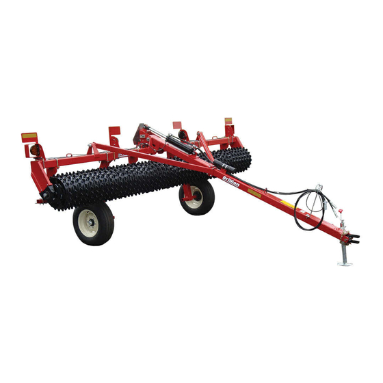
- Page 1 Transport Pulverizer with 1-3/4 Trunnion Bearing PD,PDS,PH,PHS,PHR,PO,PC,PV,PVS 10ft through 16ft Operator’s Manual LANDOLL CORPORATION 1900 North Street Marysville, Kansas 66508 (785) 562-5381 800-428-5655 ~ WWW.LANDOLL.COM F-851R0...
-
Page 3: Table Of Contents
Table of Contents Introduction and Safety Information Introduction ..............1-1 Description of Unit . - Page 4 Operation Operation of the Transport Pulverizer with Drawbar ....... 3-1 Pulverizer Preparation .
-
Page 5: Introduction And Safety Information
Failure to comply with this warning can result in within 10 days of retail purchase, using the Landoll to the personal injury or death, damage Corporation Ag Products on-line registration process. -
Page 6: Understanding Safety Statements
INTRODUCTION AND SAFETY INFORMATION When applying decals to the implement, be sure to clean NOTE the surface to remove any dirt or residue. Where possible, sign placement should protect the sign from Investigation has shown that nearly 1/3 of all farm abrasion, damage, or obstruction from mud, dirt, oil etc. -
Page 7: Maintenance Safety
INTRODUCTION AND SAFETY INFORMATION Maintenance Safety When inflating tires, use a clip-on chuck and extension hose long enough to allow you to stand to one side, not in • Block the implement so it will not roll when working on front of or over the tire assembly. -
Page 8: Safety Chain
INTRODUCTION AND SAFETY INFORMATION Safety Chain A second chain should be used between each implement. Use the safety chain to help control drawn machinery Attach the chain to the tractor drawbar support or should it separate from the tractor drawbar. specified anchor location. -
Page 9: Safety Decals
INTRODUCTION AND SAFETY INFORMATION Safety Decals Figure 1-3: Safety Decals F-851R0... - Page 10 INTRODUCTION AND SAFETY INFORMATION Figure 1-4: Safety Decal Locations 1 of 4 F-851R0...
- Page 11 INTRODUCTION AND SAFETY INFORMATION Figure 1-5: Safety Decal Locations 2 of 4 F-851R0...
- Page 12 INTRODUCTION AND SAFETY INFORMATION Figure 1-6: Safety Decal Locations 3 of 4 F-851R0...
- Page 13 INTRODUCTION AND SAFETY INFORMATION Figure 1-7: Safety Decal Locations 4 of 4 F-851R0...
- Page 14 INTRODUCTION AND SAFETY INFORMATION Table provided for general use. NOTES: 1-10 F-851R0...
-
Page 15: Assembly
Chapter 2 Assembly Using blocks or other supports, block up the CAUTION Pre-Assembled Frame. Be sure that it is secure and cannot topple. See Figure 2-1. Do not work on or under this machine unless securely blocked and supported by a hoist or tractor or by other sufficient means. -
Page 16: Wheel Arms To Frame Installation
ASSEMBLY Wheel Arms to Frame Installation 2. Install hub and spindle into wheel arm sleeve. Secure with 3/8-16 x 3 Bolt and Locknut. The distance separating the wheel arms is adjustable. It 3. Mount the wheels to the axle hubs with the 1/2-20 x 1 is recommended that the wheel arms be 7 feet apart or Wheel Bolts. - Page 17 ASSEMBLY Figure 2-3: Wheel Arm Mounting Dimensions F-851R0...
-
Page 18: Drawbar With Lift: Brace Installation
ASSEMBLY Drawbar with Lift: Brace Installation 1. Bring the rear of the Drawbar into position between the Frame Hitch Plates at the center of the Frame. Place two Machinery Bushings on each side between the Drawbar and the Frame Hitch Plates. Attach the Drawbar to the Frame with 1-1/4 x 10 Pin, Flat Washers and 5/16 x 2-1/2 Roll Pins. - Page 19 ASSEMBLY Figure 2-6: Drawbar with Lift: Brace Installation F-851R0...
-
Page 20: Hydraulic System Installation
ASSEMBLY Hydraulic System Installation: Pulverizer with lift Hydraulic Fluid Capacity = 0.75 gallon 1. Install 90 Deg ORB x Male JIC Elbow Fitting into WARNING cylinder rod end port and Restrictor into the cylinder base port. Install 90 Deg JIC x Female JIC Swivel Escaping fluid under pressure can be nearly Elbow Fitting onto Restrictor. - Page 21 ASSEMBLY Figure 2-7: Hydraulic System Installation F-851R0...
-
Page 22: Drawbar With No Lift: Brace Installation
ASSEMBLY Drawbar with No Lift: Brace Installation 1. Bring the rear of the Drawbar into position between the Frame Hitch Plates at the center of the Frame. Place two Machinery Bushings on each side between the Drawbar and the Frame Hitch Plates. Attach the Drawbar to the Frame with 1-1/4 x 10 Pin, Flat Washers and 5/16 x 2-1/2 Roll Pins. - Page 23 ASSEMBLY Figure 2-10: Drawbar with No Lift: Brace Installation F-851R0...
-
Page 24: Bridge Hitch Installation
ASSEMBLY Bridge Hitch Installation 1. At the front of the Bridge Hitch slide the Gooseneck Coupler up into the Gooseneck tube, align the top hole and insert the Bent Pin, secure with Hair Pin Cotter. 2. Thread a 3/4-10 Nut halfway onto each 3/4-10 x 2 Bolt. - Page 25 ASSEMBLY Figure 2-11: Bridge Hitch Installation F-851R0 2-11...
-
Page 26: Bridge Hitch: Brace Installation
ASSEMBLY Bridge Hitch: Brace Installation 1. Bring the rear of the Bridge Hitch into position between the frame hitch plates at the center of the frame. 2. Place one 1-1/4 x 1-7/8 Machinery Bushing on each side between the Bridge Hitch and the Hitch Plates. Line up the holes and insert 1-1/4 x 10 Pin, secure with Flat Washers and 5/16 x 2-1/2 Roll Pins. - Page 27 ASSEMBLY Figure 2-12: Bridge Hitch: Brace Installation F-851R0 2-13...
-
Page 28: Bridge Hitch: Hydraulic System Installation
ASSEMBLY Bridge Hitch: Hydraulic System Bridge Hitch Hydraulic Fluid Capacity = 1 gallon 1. Remove Fitting Caps prior to installing Fittings. Installation 2. Screw a 90 degree Male ORB X Male JIC Elbow into the rod end port and a 90 degree Male ORB x WARNING Female Swivel JIC Elbow Fitting into the base end port of the Hydraulic Cylinder. - Page 29 ASSEMBLY Figure 2-13: Bridge Hitch Hydraulic System Installation F-851R0 2-15...
- Page 30 ASSEMBLY Figure 2-14: LED Schematic 2-16 F-851R0...
-
Page 31: Pulverizer With Lift: Led Lamp And Harness Installation
ASSEMBLY Pulverizer with Lift: LED Lamp and Harness Installation NOTE Unless otherwise noted the following installation instructions apply to all Models. 1. Install outer light mount brackets approximately 2-1/2” from the Bearing Hanger Plate using 1/2-13 U-Bolts and Locknuts. See Figure 2-16. 2. - Page 32 ASSEMBLY Figure 2-16: Pulverizer with Lift: LED Lamp and Harness Installation 2-18 F-851R0...
- Page 33 ASSEMBLY Figure 2-17: Pulverizer with Lift: LED Warning Lights Installation Dimensions F-851R0 2-19...
-
Page 34: Pulverizer With No Lift: Led Lamp And Harness Installation
ASSEMBLY Pulverizer with No Lift: LED Lamp and Harness Installation NOTE Unless otherwise noted the following installation instructions apply to all Models. 1. Install the outer Light Mount Brackets approximately 2-1/2” from the Frame Bearing Hanger Plate.using 1/2-13 U-Bolts and Locknuts. See Figure 2-19. 2. - Page 35 ASSEMBLY Figure 2-19: Pulverizer with No Lift: LED Lamp and Harness Installation F-851R0 2-21...
- Page 36 ASSEMBLY Figure 2-20: Pulverizer with No Lift: LED Mounting Dimensions 2-22 F-851R0...
- Page 37 ASSEMBLY Table provided for general use. NOTES: F-851R0 2-23...
-
Page 38: Notched/Heavy Notched Scraper Installation
ASSEMBLY Notched/Heavy Notched Scraper Installation 1. With the rollers on level ground, place four 5/8-11 U-Bolts over the Frame Tube and through the Scraper Brackets. Hand tighten Flanged Locknuts. Attach the Scrapers in the bottom of the top two slots to the Scraper Tube approximately 4 inches apart, except for the four that will be attached when the tube is attached to the Scraper Brackets. - Page 39 ASSEMBLY Figure 2-22: Notched Scraper Installation F-851R0 2-25...
-
Page 40: V-Wheel Scraper Installation 10 - 12Ft
ASSEMBLY V-Wheel Scraper Installation 10 - 12ft 2. The Scraper Bar is pre-assembled with scrapers attached (spaced approximately 6 inches apart). 1. With the Rollers on level ground, place 5/8-11 Remove the eight Locknuts from the U-Bolts where U-Bolts over the frame tube and through the Scraper the Scraper Bar will attach to the Scraper Brackets. -
Page 41: V-Wheel Scraper Installation 14 - 16Ft
ASSEMBLY V-Wheel Scraper Installation 14 - 16ft 2. The Scraper Bar is pre-assembled with scrapers attached (spaced approximately 6 inches apart). 1. With the Rollers on level ground, place 5/8-11 Remove the twelve Locknuts from the U-Bolts where U-Bolts over the frame tube and through the Scraper the Scraper Bar will attach to the Scraper Brackets. -
Page 42: Sprocket 4K775 Installation - Optional
ASSEMBLY Sprocket 4K775 Installation - Optional 1. Position the sprocket between each wheel so it rides on top of wheels. See Figure 2-25. 2. Make sure the sprocket does not bind. NOTE Sprocket 4K775 is an option used only with 164648 Wheel. -
Page 43: Operation
This chapter will cover the basic operation and any time. Allowing a person to ride on the procedures for the Landoll Brillion Transport Pulverizer. machine can inflict serious personal injury or Be sure to read and understand the Safety Procedures death to that person. -
Page 44: Field Operation
OPERATION • If an operator plugs in the 7-pin connector, but the IMPORTANT lights do not seem to work right, check the above items to make sure there is a good connection with It is the responsibility of the owner/operator to the 7-pin connector. -
Page 45: Operation Of The Transport Pulverizer With Bridge Hitch
OPERATION Operation of the Transport WARNING Pulverizer with Bridge Hitch Maximum road speed is 20 MPH under good Before operating your Brillion machine check all conditions. Do not tow the machine at a speed hardware for tightness. Use the Torque Tightening Chart which makes vehicle control difficult. -
Page 46: Hitching The Bh1020 Bridge Hitch
OPERATION Hitching the BH1020 Bridge Hitch The BH1020 is designed to closely link a pulverizer with another implement. Proper hitching to the towing implement requires a hitch built to safely tow the Bridge Hitch on the road and in the field. A 2-5/16 Hitch Ball is required. -
Page 47: Hydraulic System
OPERATION Hydraulic System For Transport Raise the machine. Ensure that the lift cylinder is fully The Pulverizer is equipped with a hydraulic system to extended. Install the Transport Lock Pin for drawbar raise and lower the unit. version. See Figure 3-2. Install Transport Lock Channel ... -
Page 48: Transport
OPERATION Transport 7. Check that tires are of proper size, load rating, and inflated to manufacture specifications before 1. Check and follow all federal, state, and local transporting. Check wheel lug bolts to ensure requirements before transporting the Pulverizer. tightness. 2. -
Page 49: Maintenance
Chapter 4 Maintenance General Torque Specifications This chart provides tightening torques for general purpose applications when special torques are not specified on process or drawing. Assembly torques apply to plated nuts and capscrews assembled without supplemental lubrication (as received condition). They do not apply if special graphite moly-disulfide or other extreme pressure lubricants are used. -
Page 50: Hydraulic Fitting Torque Specifications
MAINTENANCE Hydraulic Fitting Torque Specifications 37 degree JIC, ORS, &ORB (REV. 10/97 This chart provides tightening torques for general purpose applications when special torques are not specified on process or drawing. Assembly torques apply to plated nuts and capscrews assembled without supplemental lubrication (as received condition). They do not apply if special graphite moly-disulfide or other extreme pressure lubricants are used. -
Page 51: Tires
MAINTENANCE Tires WARNING The wheels furnished with the pulverizer are designed for use of 9.5L x 15, 6 ply rib implement tires. The tires must Do not lubricate machine while machine is in be inflated to 28 psi. motion. If any guards are removed for lubricating, they must be replaced before operating. - Page 52 MAINTENANCE Figure 4-2: Lubrication Intervals F-851R0...
-
Page 53: Roller Bearing Maintenance
MAINTENANCE Roller Bearing Maintenance Washer, or a combination on either side, but all three must be used to minimize the gap. If gap cannot be If bearings are removed from frame refer to the steps properly minimized with bearing snap rings to below to ensure minimum axle load is applied to prolong outside, turn bearing around to have snap ring to bearing life. -
Page 54: Roller Axle Assemblies
MAINTENANCE Roller Axle Assemblies After an initial run of 5-10 hours, check the Roller Axle Assemblies to insure that the wheels are tight to one another. If not slide the wheels tight together and adjust the Axle Clamps. Figure 4-4: Roller Axle Assemblies Clamp Tightening Tighten the Clamp bolts evenly to achieve equal spacing between clamp section. -
Page 55: Clamp End Spacers - Optional
MAINTENANCE Clamp End Spacers - Optional Installation is the same for either kit. 1. Place the two Axle Spacers between the Axle Clamp The Clamp End Spacer Kits are used to eliminate space and the Wheel Stop. between the Axle Clamp and the Wheel Stop. 2. - Page 56 MAINTENANCE Kit Part Number 204831 - 1” Axle Spacer 2. Insert two 3/8-16 x 1 Bolts through the Axle Spacers and secure with 3/8-16 Locknuts. Kit Part Number 204832 - 1-1/4” Axle Spacer Kit Part Number 204833 - 1-1/2” Axle Spacer Refer to the Torque Table for proper bolt torque values.
-
Page 57: General Reference And Specifications
Chapter 5 General Reference and Specifications Continued on next page F-851R0... - Page 58 GENERAL REFERENCE AND SPECIFICATIONS F-851R0...
- Page 59 GENERAL REFERENCE AND SPECIFICATIONS Continued on next page F-851R0...
- Page 60 GENERAL REFERENCE AND SPECIFICATIONS F-851R0...
- Page 61 GENERAL REFERENCE AND SPECIFICATIONS Continued on next page F-851R0...
- Page 62 GENERAL REFERENCE AND SPECIFICATIONS F-851R0...
- Page 63 Document Control Revision Log: Date Revision Improvement(s) Description and Comments 8/2016 Initial Release...
- Page 64 Equipment from Landoll Corporation is built to exacting standards ensured by ISO 9001 registration at all Landoll manufacturing facilities. Transport Pulverizer with 1-3/4 Trunnion Bearing PD,PDS,PH,PHS,PHR,PO,PC,PV,PVS 10ft through 16ft Operator’s Manual Re-Order Part Number F-851R0 LANDOLL CORPORATION 1900 North Street...
Need help?
Do you have a question about the Brillion PD and is the answer not in the manual?
Questions and answers