
Related Manuals for Landoll Brillion PFT10


Summary of Contents for Landoll Brillion PFT10
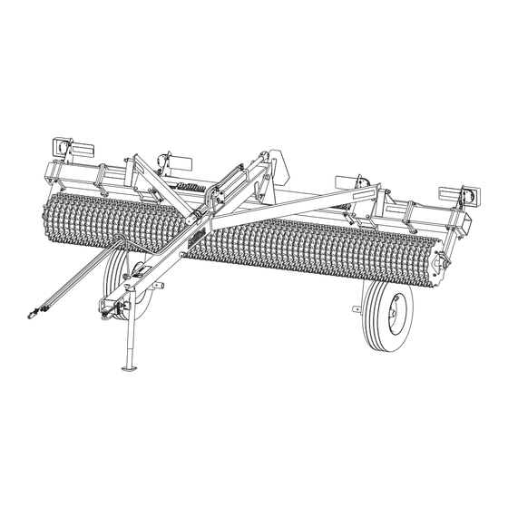
- Page 1 ‘ Floating Ring Pulverizer Models PFT10-18 Operator’s Manual LANDOLL COMPANY, LLC 1900 North Street Marysville, Kansas 66508 (785) 562-5381 800-428-5655 ~ WWW.LANDOLL.COM 5K089-2407...
- Page 2 Manuals for Float Ring Pulverizer PFT10-18 Manual Number Manual Type 5K089 Operator’s Manual 5K088 Parts Manual...
- Page 3 DANGER DO NOT operate or perform any maintenance tasks on this equipment until you have completed the following: 1. Receive proper training to operate this equipment safely. 2. Read and understand the operator’s manual. 3. Be thoroughly trained on inspection and repair procedures. Failure to comply with this warning may result in serious injury or possibly death.
- Page 5 Table of Contents Safety Introduction ............1-1 Description of Unit .
- Page 6 TABLE OF CONTENTS Transport Lock ........... . 3-4 Hydraulic Lift System .
- Page 7 Failure to comply with this warning can result in within 10 days of retail purchase, using the Landoll personal injury or death, damage to the Corporation Ag Products on-line registration process.
- Page 8 TABLE OF CONTENTS SAFETY Safety • When applying decals to the implement, be sure to clean the surface to remove any dirt or residue. Where possible, sign placement should protect the NOTE sign from abrasion, damage, or obstruction from mud, dirt, oil etc.
- Page 9 TABLE OF CONTENTS SAFETY Safety Instructions for Towing Maintenance Safety Vehicles • Block the machine so it will not roll when working on or under it. The maximum travel speed is the lesser of • Transport Locks installed. • The limit of the road conditions; •...
- Page 10 TABLE OF CONTENTS SAFETY High Pressure Fluid Safety Safety Chain Escaping fluid under pressure can be nearly invisible and • Use the Safety Chain to help control drawn machinery have enough force to penetrate the skin causing serious should it separate. injury.
- Page 11 MANUFACTURERS A S S O C I A T I O N P/N: 232188 ITEM 8 ITEM 9 2P151 ITEM 10 2-573-010198 232188 Landoll Company, LLC Marysville, Kansas www.landoll.com MODEL # mile/h SERIAL # 144193 MADE IN USA 1-573-010006 ITEM 11...
- Page 12 TABLE OF CONTENTS SAFETY Decal Locations Figure 1-4: Decal Locations 5K089-2407...
- Page 13 Chapter 2 TABLE OF CONTENTS Assembly IMPORTANT CAUTION All harnesses must be firmly attached to machine Do Not work on or under this machine unless frame members, so they don’t sag or become torn securely blocked and supported by a hoist or loose by field debris.
- Page 14 TABLE OF CONTENTS ASSEMBLY Drawbar Installation Brace 1. Bring the rear of the Drawbar into position between the Frame Hitch Plates at the center of the Frame. Do Not over tighten, Brace must be free to pivot Place two 1-1/4 x 1-7/8 x 14 ga Machinery Bushings on each side between the Drawbar and the Frame Pivot Hardware Hitch Plates.
- Page 15 TABLE OF CONTENTS ASSEMBLY Locknut,1-1/4-7 Lynch Pin, 1/4 x 1-1/4 Bolt, 1-1/4-7 x 10-1/2 Locknut,1-8 Flat Washer,1" Machinery Bushing Flat Washer,1" Hyd Cyl Brace 4 x 16 Bolt,1-8 x 5-1/2 Locknut,5/8-11 Brace Bolt,5/8-11 x 8 Hose Support PFT10-18 OpDrawbar Bolt, Drawbar 5/8-11 x 2 Assembly...
- Page 16 TABLE OF CONTENTS ASSEMBLY Wheel Arm Assembly Attach the Wheel Arms to the Frame. The Wheel Arms should be equally spaced from the center of the machine. See Figure 2-5. Fasten the Wheel Arms to the Frame with 4 Hole Plates and eight 3/4-10 x 9-1/2 Bolts and Locknuts. Insert the Hub and Spindle Assembly into the Wheel Arms, using the hole in the spindle which is closest to the hub.
- Page 17 TABLE OF CONTENTS ASSEMBLY Bolt, 3/4-10 x 9-1/2 4 Hole Plate Locknut,3/4-10 Wheel Arm Tire and Wheel Locknut,1/2-13 Bolt,1/2-13 x 3 Hub and Spindle PFT10-18 OpWhlArms Wheel Bolt, 1/2-20 x 1 Figure 2-6: Wheel Arm Assembly 5K089-2407...
- Page 18 TABLE OF CONTENTS ASSEMBLY Hydraulic Circuit Installation Hydraulic Assembly CAUTION WARNING Do not raise the machine without the use of Escaping fluid under pressure can be nearly hydraulics. This would introduce air into the invisible and have enough force to penetrate the hydraulic cylinder.
- Page 19 TABLE OF CONTENTS ASSEMBLY Hyd Cyl Elbow,90°, 4 x 16 8MJ x 8FJS Restrictor Hose Asm, 3/8 x 185 Hose Asm, 3/8 x 161 PFT10-18 HydLayout Adapter,8MJ X 8MOR Male Coupler,8 O-Ring Figure 2-8: Hydraulic Circuit Installation 5K089-2407...
- Page 20 TABLE OF CONTENTS ASSEMBLY Warning Lamp Installation IMPORTANT All Harnesses must be firmly attached to machine 1. Remove the two inner Bearing Support 5/8-11 x 9-1/2 frame members or Hydraulic Hoses so they do not Bolts and Locknuts. Set the outer Light Mount sag or become torn loose by field debris.
- Page 21 TABLE OF CONTENTS ASSEMBLY Figure 2-10: Lamp Installation 5K089-2407...
- Page 22 TABLE OF CONTENTS ASSEMBLY Single and Dual Wheel Kits - Optional Locknut,3/4-10 Bolt,3/4-10 x 9-1/2 4 Hole Plate Wheel Arm Nut,1/2-13 Tire and Wheel Bolt, 1/2-13 x 3 Bolt,1/2-20 x 1 Hub and Spindle Nut,1/2-13 Hub and Spindle Tire and Wheel Bolt, 1/2-13 x 3 Bolt,1/2-20 x 1...
- Page 23 Chapter 3 TABLE OF CONTENTS Operation DANGER DANGER DANGER DANGER Never allow anyone a ride on the seeder at any Always lock the tractor drawbar in the center time. Allowing a person to ride on the machine can position when transporting the unit. Failure to do inflict serious personal injury or death to that so can result in serious injury or death and cause person.
- Page 24 TABLE OF CONTENTS OPERATION Operation of the PFT Attaching PFT Pulverizer Pulverizer with Drawbar The PFT Pulverizer is designed to be pulled behind tractors, seeders, or tillage tools. The long drawbar allows Pulverizer Preparation for easy turns when pulled behind other equipment. When attaching the pulverizer to a tractor or implement 1.
- Page 25 TABLE OF CONTENTS OPERATION DRAWBAR JACK POSITION Drawbar Jack mounted on 2nd Jack Swivel Mount Jack Retracted 18-3/4" Jack Extended Drawbar Jack mounted on 3rd Jack Swivel Mount Jack Retracted Jack Extended Figure 3-2: 2nd and 3rd Jack Swivel Positions 5K089-2407...
- Page 26 TABLE OF CONTENTS OPERATION Transport Lock Parking The safest way to park your pulverizer is to lower it into the operating position, place blocks behind and in front of the CAUTION pulverizer wheels, then use the jack to take the weight off Be sure to install the Transport Lock Pin any time the towing implement and unhitch the machine.
- Page 27 TABLE OF CONTENTS OPERATION Hydraulic Lift System Roller Orientation The drum assembly can be mounted to the frame in two The PFT Pulverizer is equipped with a Hydraulic Lift ways. When mounted as shown the wheels will have a System to raise and lower the unit in the field. tendency to pack the soil.
- Page 28 TABLE OF CONTENTS OPERATION Transport 6. Before transporting: • Know the height and width of the implement being 1. Check and follow all federal, state, and local towed. Markers, tanks, attachments, etc. can requirements before transporting the Pulverizer. increase the height and width of the implement. 2.
- Page 29 Chapter 4 TABLE OF CONTENTS Maintenance General Torque Specifications (rev. 4/97) This chart provides tightening torques for general purpose applications when special torques are not specified on process or drawing. Assembly torques apply to plated nuts and capscrews assembled without supplemental lubrication (as received condition). They do not apply if special graphite moly-disulfide or other extreme pressure lubricants are used.
- Page 30 TABLE OF CONTENTS MAINTENANCE Hydraulic Fitting Torque Specifications 37 degree JIC, ORS, &ORB (REV. 10/97 This chart provides tightening torques for general purpose applications when special torques are not specified on process or drawing. Assembly torques apply to plated nuts and capscrews assembled without supplemental lubrication (as received condition). They do not apply if special graphite moly-disulfide or other extreme pressure lubricants are used.
- Page 31 TABLE OF CONTENTS MAINTENANCE Tires Lubrication Maintenance Recommended Tire Size: 11L - 15 - 12 PLY Lubricated bearings with quality grease per recommended lubrication frequency intervals indicated or Tire Inflation Pressure: 52 PSI if machine is not used for an extended period. Greaseable When Re-Installing 1/2-20 x 1, Wheel Bolts tighten to components are the same on each side.
- Page 32 TABLE OF CONTENTS MAINTENANCE Hydraulic Maintenance Replacing or Adding Roller Wheels IMPORTANT Although the roller wheels are manufactured from high Lower the Pulverizer to the ground, and relieve grade ductile iron, wear or breakage may require that hydraulic pressure before attempting to service any some wheels be periodically replaced.
- Page 33 TABLE OF CONTENTS MAINTENANCE Roller Wheel Drum 2" MIN Pillow Block Bearing Block Drum Contacting Roller Wheels Figure 4-4: Pillow Block Bearing Frame Bolt,5/8-11 x 9-1/2 Plate Bearing Support Drum Nut,Lock 5/8-11 Pillow Block Bearing Roller Wheel Eccentric Locking Collar Retainer Plate Nut,Lock 5/8-11 Figure 4-5: Roller Wheels Removal...
- Page 34 TABLE OF CONTENTS MAINTENANCE Warning Lamps Storage When plugging in the 7-Pin Warning Lamp Connector: 1. The service life of the Pulverizer will be extended by proper off-season storage practices. Prior to storing 1. Make sure the Tractor has a good clean Receptacle, the unit, complete the following procedures: free of dirt and corrosion.
- Page 35 Chapter 5 TABLE OF CONTENTS Specifications Product Attributes PPF6B12 PPF8B12 PPF10B12 Approximate Weight 1,601 lbs. (720 kg) 2,020 lbs. (909 kg) 2,580 lbs. (1,161 kg) Working Width 6 ft. 0 in. (1.8 m) 8 ft. 0 in. (2.4 m) 10 ft. 0 in. (3 m) Transport Width 7 ft.
- Page 36 TABLE OF CONTENTS SPECIFICATIONS Product Attributes PPF12B12 PPF14B12 PPF15B12 Approximate Weight 3,056 lbs. (1,375 kg) 3,490 lbs. (1,571 kg) 3,729 lbs. (1,678 kg) Working Width 12 ft. 0 in. (3.6 m) 14 ft. 0 in. (4.2 m) 15 ft. 0 in. (4.5 m) Transport Width 13 ft.
- Page 37 TABLE OF CONTENTS SPECIFICATIONS Product Attributes PPF16B12 PPF17B12 PPF18B12 Approximate Weight 3,924 lbs. (1,765 kg) 4,350 lbs. (1,958 kg) 4,385 lbs. (1,973 kg) Working Width 16 ft. 0 in. (4.8 m) 17 ft. 0 in. (5.1 m) 18 ft. 0 in. (5.4 m) Transport Width 17 ft.
- Page 38 TABLE OF CONTENTS SPECIFICATIONS Product Attributes PFT10B12 PFT12B12 PFT14B12 Approximate Weight 3,205 lbs. (1,442 kg) 3,681 lbs. (1,656 kg) 4,115 lbs. (1,852 kg) Working Width 10 ft. 0 in. (3 m) 12 ft. 0 in. (3.6 m) 14 ft. 0 in. (4.2 m) Transport Width 11 ft.
- Page 39 TABLE OF CONTENTS SPECIFICATIONS Product Attributes PFT15B12 PFT16B12 PFT17B12 Approximate Weight 4,354 lbs. (1,959 kg) 4,549 lbs. (2,047 kg) 4,775 lbs. (2,149 kg) Working Width 15 ft. 0 in. (4.5 m) 16 ft. 0 in. (4.8 m) 17 ft. 0 in. (5.1 m) Transport Width 16 ft.
- Page 40 TABLE OF CONTENTS SPECIFICATIONS Product Attributes PFT18B12 PFT20B12 PFT22B12 Approximate Weight 4,998 lbs. (2,249 kg) 6,120 lbs. (2,776 kg) 6,599 lbs. (2,993 kg) Working Width 18 ft. 0 in. (5.4 m) 20 ft. 0 in. (6.1 m) 22 ft. 0 in. (6.7 m) Transport Width 19 ft.
- Page 41 Document Control Revision Log: Date Form # Improvement(s): Description and Comments 02/2015 5K089-0215 Updated Drawings 07/2024 5K089-2407 ECN -50088 Added Decals: QR Code, Fema, MPH Revised Template Updated ISO logos to ISO 9001:2015...
- Page 42 Equipment from Landoll Company, LLC is built to exacting standards ensured by ISO 9001:2015 registration at all Landoll manufacturing facilities. Floating Ring Pulverizer Models PFT10-18 Operator’s Manual Re-Order Part Number 5K089 LANDOLL COMPANY, LLC 1900 North Street Marysville, Kansas 66508 (785) 562-5381 800-428-5655 ~ WWW.LANDOLL.COM...
Need help?
Do you have a question about the Brillion PFT10 and is the answer not in the manual?
Questions and answers