
Related Manuals for Landoll Till ‘N Seed BPS6


Summary of Contents for Landoll Till ‘N Seed BPS6
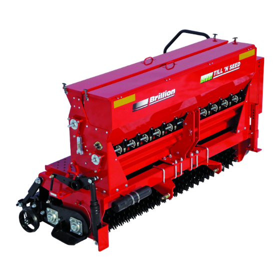
- Page 1 Till ‘N Seed ® Models BPS6 and BPSB6 Operator’s Manual LANDOLL CORPORATION 1900 North Street Marysville, Kansas 66508 (785) 562-5381 800-428-5655 ~ WWW.LANDOLL.COM 311rev0114 3P091...
-
Page 3: Table Of Contents
Table of Contents Safety Information Introduction ..............1-1 Description of Unit . - Page 4 Acre Meter Operations ............3-3 Settings for Loup Acre Meters After 05/15/2012 .
-
Page 5: Safety Information
10 days of retail purchase, using the Landoll Corporation Ag Products on-line registration process. Description of Unit Please refer to the Ag Products Policy and Procedures Manual, accessible at www.landoll.com... -
Page 6: Understanding Safety Statements
SAFETY INFORMATION Federal law requires that you explain the safety and • Keep these signs clean so they can be observed operating instructions furnished with this machine to all readily. It is important to keep these decals cleaned operators before they are allowed to operate the more frequently than the machine. -
Page 7: Attaching, Detaching, Storage
SAFETY INFORMATION • Keep clear of overhead power lines and other • After attaching implement to the tractor and prior to obstructions when transporting. Know transport height lifting the machine, loosed nut on Rockshaft Clamp and width of your machine. enough to allow movement and remove the Rockshaft Lock Detent Pin. -
Page 8: Maintenance Safety
SAFETY INFORMATION Maintenance Safety Prepare for Emergencies • Block the machine so it will not roll when working on or • Keep a First Aid Kit and Fire Extinguisher handy under it to prevent injury in case of hydraulic failure or •... -
Page 9: Decals
SAFETY INFORMATION Decals Figure 1-3: Decals (1 of 5) - Page 10 SAFETY INFORMATION Figure 1-4: Decals (2 of 5) 3P091...
- Page 11 SAFETY INFORMATION Figure 1-5: Decals (3 of 5)
- Page 12 SAFETY INFORMATION Figure 1-6: Decals (4 of 5) 3P091...
- Page 13 SAFETY INFORMATION Figure 1-7: Decals (5 of 5)
- Page 14 SAFETY INFORMATION Figure 1-8: Slow Moving Vehicle Sign 1-10 3P091...
-
Page 15: Operation
Chapter 2 Operation Operation of Till ‘N Seed DANGER Your BRILLION TILL 'N SEED is fully assembled from Always be sure the front of the tractor has the factory. This section refers to how to enough weight to maintain control when the successfully operate your machine. -
Page 16: Attaching To A Tractor
OPERATION Attaching to a Tractor • If an offset is required for wider tractors, move the • Your implement requires a tractor with a lift capacity of Three Point Hitch towards the transmission side of the 2,150 lbs, 24 inches behind the lift pins. Compatible machine. - Page 17 OPERATION • After attaching the implement to the tractor and prior to lifting the machine, loosen the nut on Rockshaft Clamp enough to allow movement and remove the Rockshaft Lock Detent Pin. Insert Detent Pin in the storage hole on Rockshaft Arm. Raise the Stand. See Figure 2-3. Figure 2-3: Rockshaft Lock...
-
Page 18: Front Seedbox Seed Chart
OPERATION Front Seedbox Seed Chart Rates are intended as a guide only. Variations in size and cleanliness will affect rates. Calibrate desired seed for best results. Front Box 5K141 Seed Meters. (1 ACRE = 43,560 SQ. FT. = 6 FT wide x 1-3/8 mile. See Figures 2-4 and 2-5. - Page 19 OPERATION Figure 2-5: Front Seedbox Seed Chart (2 of 2)
-
Page 20: Rear Seedbox Seed Chart
OPERATION Rear Seedbox Seed Chart Rear Box 4C589 Seed Meters. Standard on the BPSB-6. Figure 2-6: Rear Seedbox Seed Chart 3P091... -
Page 21: Seed Rate
OPERATION Seed Rate • To install sprockets for the required range, remove the Klik Pin and change the Driver and Driven Sprockets Refer to Seed Chart on the Front Seedbox Cover to accordingly. Also, refer to decal on the inside of the determine range for Seeding Rate. - Page 22 OPERATION • All cups must be set the same to seed uniformly. CAUTION Check by using the wrenches provided and loosening the Inner Adjusting Nut and turning the Outer Seed To prevent damage to seed meters, do not apply Rate Adjusting Nut so that the Seed Cups close.
-
Page 23: Rear Seedbox
OPERATION Rear Seedbox NOTES • Rear Seedbox cups are adjusted just like the Front Rear Seedbox Seed Cups discharge to the rear of the Seedbox. machine. Figure 2-9: Rear Seedbox Cups... -
Page 24: Seed Rate Calibration
OPERATION Seed Rate Calibration 2. Adjust Seed Meter Setting. 3. Remove Seed Drive Disconnect Pin - Front Box. Place Calibration Trough in Collection Position by 4. Prime Meters: Turn 5/8" Hex for Front Box Calibration removing (6) six Carriage Bolts. See Figure 2-11. Place CW (Clockwise) until all Meters are discharging tarp under front of machine. -
Page 25: Rear Seedbox
OPERATION Rear Seedbox 4. Turn the 5/8" Hex CCW 143 revolutions to meter out seed. 1. Adjust Seed Meter Setting. 5. Weigh the seed = Lbs / Acre. 2. Remove Seed Drive Disconnect Pin - Rear Box. 6. Adjust Meters and Re-Calibrate as necessary. 3. -
Page 26: Seeding
OPERATION Make sure you cut the seeding rate in half when planting DANGER in two passes. • In most conditions, a single pass will be sufficient. If Keep riders off of machinery conditions dictate, two or more tillage passes may be Do not allow anyone to ride on tractor or done. -
Page 27: Air Shock
OPERATION • Typical air pressure range for this Implement is 20-100 DANGER psi. In some instances more air pressure maybe necessary, but do not exceed 120psi. Optimal air Wear Protective Gloves And Safety Glasses Or pressure will vary depending soil conditions. Goggles When Working With Air Shock. -
Page 28: Gage Wheels
OPERATION Gage Wheels • Engaging the Gage Wheels with the ground will also help reduce Tillage Rotor bounce. • Gage Wheels control the depth of the Tillage Rotor. Figure 2-14: Gage Wheels 2-14 3P091... -
Page 29: Rotor Thrust Guide
OPERATION Rotor Thrust Guide • If adjustment is needed loosen Jam Nut and turn Adjusting Bolt, Re-tighten Jam Nut. • Thrust Guide on each side of the machine, should Right side of the machine shown. have 1/32" maximum clearance between Guide and Lower Frame Side Plates. -
Page 30: Lift And Tie-Down
OPERATION Lift and Tie-Down • Tighten nut on Rockshaft Clamp to prevent movement. • Before lifting Implement Open Rear Seedbox Cover to • Before loading Implement onto a trailer and detaching prevent possible damage during lifting. Tie machine from tractor, lower machine to the ground and install down on the trailer and close Rear Seedbox Cover. -
Page 31: Storage
OPERATION Storage • Repair or replace any broken or damaged parts. • Store in a dry, protected place. • At the end of the season, empty Seedboxes and Seed • Before detaching implement from tractor, lower Meters before cleaning your machine for storage. machine to the ground and tighten nut on Rockshaft •... - Page 32 OPERATION Page Intentionally Blank 2-18 3P091...
-
Page 33: Optional Equipment Instructions
Chapter 3 Optional Equipment Instructions Acre Meter Kit 3P099 Installation hardware and Tighten.Attach Pick-up Switch Bracket to the Lower Frame with 5/16-18 Hardware. The Acre Meter Kit consists of four main parts; Acre 2. Attach Pick-up Switch to Bracket with #8-32 Meter Assembly, Pick-up Switch Bracket, Pick-up Switch, Hardware. - Page 34 OPTIONAL EQUIPMENT INSTRUCTIONS Alignment of Pick-up Switch and Magnet Wheel is WARNING critical. Improper alignment will cause the Acre Meter to record acres erratically or not at all. Do Not Pressure Clean With Air Or Water. 6. Route Pick-up Switch Cable up to the Acre Meter Cable and connect mating plugs.
-
Page 35: Acre Meter Operations
OPTIONAL EQUIPMENT INSTRUCTIONS Acre Meter Operations If you do not know the pulses per mile, press and hold the UP and DOWN buttons until the “0000” appears in the display. The “PULSES” LED will blink. The acre counter Settings for Loup Acre Meters After is now counting shaft rotations. -
Page 36: Quick-Start Settings For Loup Acre Meters Prior To 05/15/2012
OPTIONAL EQUIPMENT INSTRUCTIONS Changing The Password 3. Press the function button to set password; screen will show “(set)”. Record number - it is required if you Select a new password using the UP and DOWN buttons. decide to disable password. Press the /FUNC button until the word “SEt”... - Page 37 OPTIONAL EQUIPMENT INSTRUCTIONS Table 3-1: Acre Meter Settings (After 05/15/2012) MODEL PULSES WIDTH SSP T604 SSP4 SSP5 SSP6 SSP8 SSP10 SS10 10.0 SSP12 SS12 12.0 SSP108 SS108 SSP110 SS110 10.0 SSP112 SS112 12.0 SSP208 SSP2081 SS208 SS2081 SSP210 SSP2101 SS210 SS2101 10.0 SSP212...
- Page 38 OPTIONAL EQUIPMENT INSTRUCTIONS Table 3-2: Acre Meter Settings (Prior to 05/15/2012) MODEL Pulses Width SSP T604 SSP4 SSP5 SSP6 SSP8 SSP10 SS10 SSP12 SS12 SSP108 SS108 SSP110 SS110 SSP112 SS112 SSP208 SSP2081 SS208 SS2081 SSP210 SSP2101 SS210 SS2101 SSP212 SSP2121 SS212 SS2121 SSP308...
-
Page 39: Small Seedbox Kit 3P100
OPTIONAL EQUIPMENT INSTRUCTIONS Small Seedbox Kit 3P100 • Install Small Seedbox onto Machine per the following illustrations. Start with the Deflector. Figure 3-3: Small Seedbox Kit (1 of 3) - Page 40 OPTIONAL EQUIPMENT INSTRUCTIONS Figure 3-4: Small Seedbox Kit (2 of 3) 3P091...
- Page 41 OPTIONAL EQUIPMENT INSTRUCTIONS Figure 3-5: Small Seedbox Kit (3 of 3)
- Page 42 OPTIONAL EQUIPMENT INSTRUCTIONS Table provided for general use. NOTES: 3-10 3P091...
-
Page 43: Maintenance
Chapter 4 Maintenance General Torque Specifications This chart provides tightening torques for general purpose applications when special torques are not specified on process or drawing. Assembly torques apply to plated nuts and capscrews assembled without supplemental lubrication (as received condition). They do not apply if special graphite moly-disulfide or other extreme pressure lubricants are used. - Page 44 MAINTENANCE Hydraulic Fitting Torque Specifications 37 degree JIC, ORS, &ORB (REV. 10/97 This chart provides tightening torques for general purpose applications when special torques are not specified on process or drawing. Assembly torques apply to plated nuts and capscrews assembled without supplemental lubrication (as received condition). They do not apply if special graphite moly-disulfide or other extreme pressure lubricants are used.
-
Page 45: Lubrication
MAINTENANCE • Lubricate Roller Chains periodically with quality chain WARNING oil. For best penetration, lubricate chain immediately after Do Not Lubricate Machine While Machine Is In use while chain is still warm. Motion. If Any Guards Are Removed For Lubricating, They Must Be Replaced Before NOTE Operating. - Page 46 MAINTENANCE Figure 4-2: Lubrication (2 of 2) 3P091...
-
Page 47: Chain Tension
MAINTENANCE Chain Tension • The Rotor Drive Chain is properly adjusted when it has a 1/4" - 5/16" deflection across the top of the sprockets, while the bottom is tight. If adjustment is needed loosen the Hex Nut and turn the Adjustment Bolt until the proper deflection is achieved. - Page 48 MAINTENANCE Figure 4-3: Chain Tension (1 of 2) • The Small Seedbox Drive Chain and Seedbox Drive Chain is properly adjusted when it has 1/8" - 3/16" deflection across the sprockets. • The Primary Drive Chain is properly adjusted at 5/16" - 3/8"...
- Page 49 MAINTENANCE Figure 4-4: Chain Tension (2 of 2)
-
Page 50: Rotor Thrust Guide
MAINTENANCE Rotor Thrust Guide • On each side of the machine, check the 1/32” maximum clearance between the Thrust Guide and Lower Frame Side Plate. WARNING • If adjustment is needed loosen Jam Nut and turn Adjusting Bolt. Retighten Jam Nut. Support machine with blocks or stands when working on or under it to prevent injury in case of Right side of the machine is shown. -
Page 51: Rotor Blade
MAINTENANCE Rotor Blade Firming Roller • Check and replace bent or damaged Rotor Blades. • Check the Firming Roller regularly for tightness between wheels, if adjustment is needed loosen the • Regularly check Rotor Blade tightness, if adjustment is Hex Nuts and Slide the clamp over. Re-tighten Hex needed remove Roll Pin and torque the Slotted Hex Nuts. -
Page 52: Maintenance Chart
MAINTENANCE Maintenance Chart (Subject to change without notice) Initial Run - In 8 Hours 25 Hours Annually Storage Fasteners Grease Rockshaft bearings Grease Rockshaft Link Grease Guide Wheel Hub Grease Rotor and Roller Bearings Lubricate Roller Chains Adjust Roller Chain tension Adjust Rotor Thrust Guide Tighten Rotor Blades and Roller Wheels... -
Page 53: Troubleshooting
MAINTENANCE Troubleshooting Problem Solution Machine is shaking or Tillage Rotor is Engage Gage Wheels with ground bouncing Reduce operating depth of Tillage Rotor Increase air pressure in Air Shock Machine is shaking and Drive Rotor is Check if rotors are plugged not Turning Check rotor drive chain Drive Rotor is skidding... - Page 54 MAINTENANCE Table provided for your general use with this manual. NOTES: 4-12 3P091...
-
Page 55: Reference Tables And Specifications
Chapter 5 Reference Tables and Specifications Model Designation BPS6 BPSB6 Weight (Empty) 2004 lbs 2111 lbs Tractor Lift Capacity 2050 lbs (24” behind Lift Arms) 2150 lbs (Behind Lift Arms) Seed Box Front Box Only Front and Rear Box Seedbox capacity 4.5 Bushels 4.5 Bushels and 1.4 Bushels Seed Metering... - Page 56 REFERENCE TABLES AND SPECIFICATIONS Table provided for your general use with this manual. NOTES: 3P091...
- Page 57 Document Control Revision Log: Date Revision Improvement(s) Description and Comments 03/2011 311rev0511 Initial Release 09/2011 311rev0911 Updated, Incorporated Landoll Format 03/2013 311rev0313 Added New Acre Meter Data 01/2014 311rev0114 Added Patent Decal. Manufactured under Patent #8,590,632...
- Page 58 Equipment from Landoll Corporation is built to exacting standards ensured by ISO 9001 registration at all Landoll manufacturing facilities. Till ‘N Seed ® Models BPS6 and BPSB6 Operator’s Manual Re-Order Part Number 3P091rev0114 LANDOLL CORPORATION 1900 North Street Marysville, Kansas 66508 (785) 562-5381 800-428-5655 ~ WWW.LANDOLL.COM...
Need help?
Do you have a question about the Till ‘N Seed BPS6 and is the answer not in the manual?
Questions and answers