
Subscribe to Our Youtube Channel
Related Manuals for Extron electronics MediaLink MLM-WB+


Summary of Contents for Extron electronics MediaLink MLM-WB+
- Page 1 im Vertrieb von CAMBOARD Electronics MLM-WB+ MediaLink Wall Box Mounting Option 68-609-01 Rev. A Printed in the USA 02 04 www.camboard.de Tel. 07131 911201 ce-info@camboard.de Fax 07131 911203...
- Page 2 im Vertrieb von CAMBOARD Electronics Precautions Safety Instructions • English Warning This symbol is intended to alert the user of important operating and maintenance Power sources • This equipment should be operated only from the power source indicated on the product.
-
Page 3: Table Of Contents
im Vertrieb von CAMBOARD Electronics Table of Contents Chapter 1 • Introduction ....................... 1-1 About the MLM-WB+ ......................1-2 Chapter 2 • Installation ......................2-1 Installation Overview ....................... UL Requirements ......................... 2-3 Components, Hardware, and Required Tools ............2-3 Main MLM-WB+ components ................... 2-3 Included mounting hardware ................... - Page 4 im Vertrieb von CAMBOARD Electronics Table of Contents, cont’d www.camboard.de Tel. 07131 911201 ce-info@camboard.de MLM-WB+ • Table of Contents Fax 07131 911203...
-
Page 5: Chapter 1 • Introduction
im Vertrieb von CAMBOARD Electronics MLM-WB+ Chapter One Introduction About the MLM-WB+ www.camboard.de Tel. 07131 911201 ce-info@camboard.de Fax 07131 911203... -
Page 6: About The Mlm-Wb
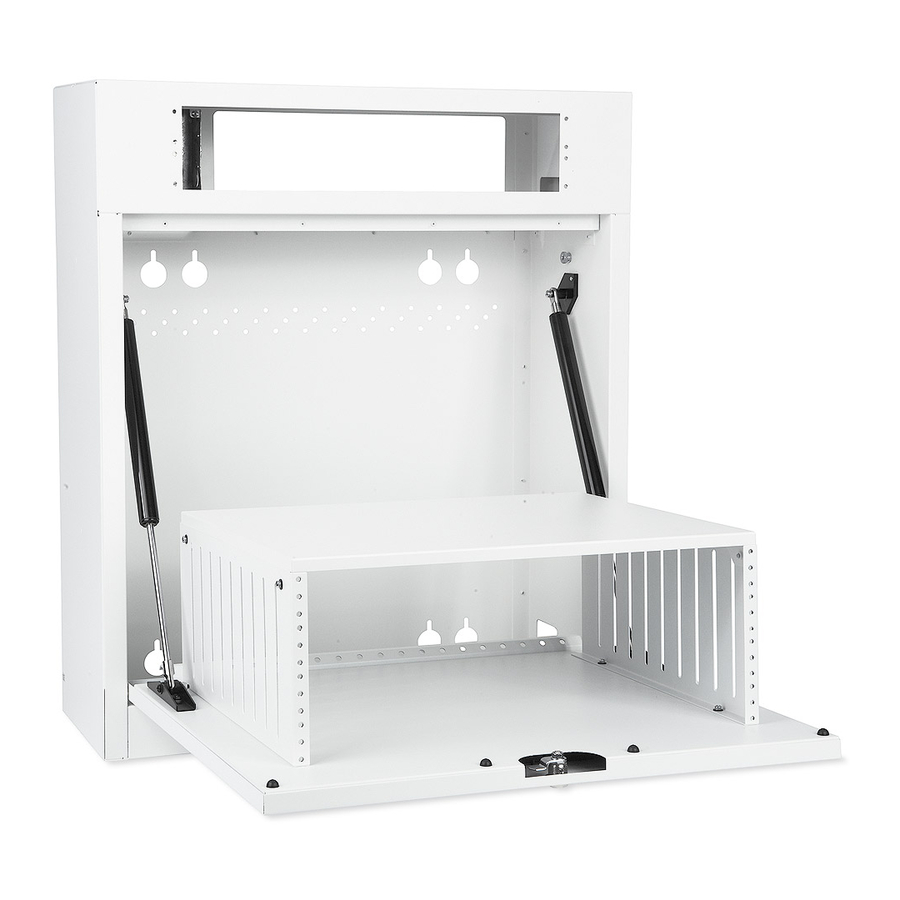
im Vertrieb von CAMBOARD Electronics Introduction About the MLM-WB+ The Extron MLM-WB+ is a locking metal wall box with two enclosures for mounting A/V equipment. The upper, 2U rack enclosure can hold Extron mounting frames and faceplates for mounting Architectural Adapter Plates (AAPs) and control pads such as the ®... -
Page 7: Chapter 2 • Installation
im Vertrieb von CAMBOARD Electronics MLM-WB+ Chapter Two Installation Installation Overview UL Requirements Components, Hardware, and Required Tools Adjusting the Door Angle Mounting the MLM-WB+ Routing Cables into the MLM-WB+ Installing Equipment Testing the Installation Completing the Installation Adjusting the Door Lock www.camboard.de Tel. -
Page 8: Installation Overview
im Vertrieb von CAMBOARD Electronics Installation Installation Overview All installation and service procedures should be performed by an Extron CAUTION authorized installer or a qualified electrician. Extron is not responsible for equipment failure or damage occurring as a result of improper installation. Contact a contractor or hardware specialist for assistance with the installation. -
Page 9: Ul Requirements
im Vertrieb von CAMBOARD Electronics UL Requirements The Underwriters Laboratories (UL) requirements listed below pertain to the installation of an MLM-WB+ wall box. Power supplies used with devices such as the MLC must be secured in the MLM-WB+ with the flat side down. You must use a UL listed junction box. -
Page 10: Included Mounting Hardware
im Vertrieb von CAMBOARD Electronics Installation, cont’d Included mounting hardware (6) 1/4" x 1 3/4" Masonry Screws #40-373-01 (4) 1/4-20 x 2" Pan Head Bolts #40-375-01 (6) #14 x 1 3/4" Self-tapping Metal/Wood Screws #40-372-01 (4) 1/4" Kap Toggle Assemblies (6) 1/4"... -
Page 11: Mounting The Mlm-Wb
im Vertrieb von CAMBOARD Electronics Mounting the MLM-WB+ The procedures in this section enable you to securely mount the MLM-WB+ to a masonry or nonmasonry wall. These procedures assume that you have already unpacked the MLM-WB+ and installed necessary cables into the wall or conduits in conformance with local and national electrical codes and equipment size requirements. -
Page 12: Mounting The Mlm-Wb+ On A Masonry Wall
im Vertrieb von CAMBOARD Electronics Installation, cont’d Mounting the MLM-WB+ on a masonry wall To mount the MLM-WB+ onto a brick, stone, or concrete wall: With the help of at least one other person, hold the MLM-WB+ against the wall and use a carpenter’s level or similar tool as a guide for leveling the unit. Mark at least six locations for masonry screws to ensure the strength and stability of the installation. -
Page 13: Mounting The Mlm-Wb+ On A Nonmasonry Wall
im Vertrieb von CAMBOARD Electronics Align the slotted mounting holes ( ) in the back of the MLM-WB+ with the screws in the wall. Move the MLM-WB+ forward over the washers and down as shown at right. Insert a masonry screw and washer through each round mounting hole on the MLM-WB+ enclosure for which you drilled a pilot hole. - Page 14 im Vertrieb von CAMBOARD Electronics Installation, cont’d Drill pilot holes in the wall at the locations you marked in step 4. • If drilling into a stud, make each hole 1.75" (4.4 cm) deep. • If drilling into the wall where no stud is present, make each hole through to the hollow part of the wall.
-
Page 15: Routing Cables Into The Mlm-Wb
im Vertrieb von CAMBOARD Electronics Align the slotted mounting holes ( ) in the back of the MLM-WB+ with the screws or toggle bolts in the wall. Move the MLM-WB+ forward over the washers and down as shown at right. Insert a self-tapping screw and washer into each round mounting hole on the MLM-WB+ enclosure for which you drilled a pilot hole. - Page 16 im Vertrieb von CAMBOARD Electronics Installation, cont’d Connect the ground wire to the junction box and to the grounding poles of the two duplex power receptacles. Ring terminals may be required for each lead. Connect the neutral and hot (positive) supply wires to the corresponding poles on the receptacles.
-
Page 17: Installing A/V And Control Cables
im Vertrieb von CAMBOARD Electronics Leave sufficient power cables to power devices in the 2U rack enclosure. Feed the remaining power cables through the small rectangular openings in the left side panel to route cables to the 4U rack enclosure. Routing power cables through the MLM-WB+ side panel Installing A/V and control cables This section explains how to route A/V and control cables through the MLM-WB+. -
Page 18: Installing Equipment
im Vertrieb von CAMBOARD Electronics Installation, cont’d Routing A/V cables through the MLM-WB+ side panel Installing Equipment This section explains how to install and cable equipment in the 2U rack enclosure and the 4U rack enclosure. Installing and cabling equipment in the 2U rack enclosure The 2U rack enclosure accommodates 1U and 2U faceplates or any Extron ®... -
Page 19: Installing And Cabling Equipment In The 4U Rack Enclosure
CAMBOARD Electronics im Vertrieb von pt op D VD D VD Installing faceplate-mounted equipment in the 2U rack enclosure Installing and cabling equipment in the 4U rack enclosure The 4U rack enclosure is designed to hold full-rack wide equipment such as switchers, VCRs, and DVD players. - Page 20 im Vertrieb von CAMBOARD Electronics Installation, cont’d Remove the screws attaching the adjustable clamp brackets to the inside of the enclosure. Set the brackets and cover aside. Stack equipment on the door, making sure not to exceed the maximum equipment height of 5.5" (14.0 cm) or the maximum rack depth of 16.0" (40.6 cm).
-
Page 21: Testing The Installation
im Vertrieb von CAMBOARD Electronics • Using mounting screws to secure each piece of equipment with rack mounting ears to the holes in the enclosure. pt op D VD D VD 5 IP CLIP SIGN IT C T SE Securing equipment with rack mounting ears Do not tighten the clamps or screws completely until you have tested the installation and made any necessary adjustments to the cabling or switch settings. -
Page 22: Completing The Installation
CAMBOARD Electronics im Vertrieb von Installation, cont’d Completing the Installation Once you have pretested the installation and made any adjustments necessary, you can secure all equipment in the MLM-WB+. Secure the equipment in the 4U rack enclosure by completely tightening the clamps or rack mounting screws. -
Page 23: Adjusting The Door Lock
im Vertrieb von CAMBOARD Electronics Adjusting the Door Lock By default, the key to the door lock cannot be removed when the door is unlocked. To adjust the lock so that the key can be removed at any time: Remove the nut, washer, and cam and set them aside. Remove the stop washer, flip it over, and then thread it back onto the screw. - Page 24 im Vertrieb von CAMBOARD Electronics Installation, cont’d www.camboard.de Tel. 07131 911201 ce-info@camboard.de 2-18 MLM-WB+ • Installation Fax 07131 911203...
-
Page 25: Appendix A • Specifications, Part Numbers, Accessories, And Dimensions
im Vertrieb von CAMBOARD Electronics MLM-WB+ A ppendix A Specifications, Part Numbers, Accessories, and Dimensions Specifications Part Numbers and Accessories www.camboard.de Tel. 07131 911201 ce-info@camboard.de Fax 07131 911203... - Page 26 im Vertrieb von CAMBOARD Electronics Specifications, Part Numbers, Accessories, Dimensions Specifications General Power ..........Not powered Rack mount ........No, but wall-mountable with included hardware Enclosure type ......Metal Enclosure dimensions Closed ........ 26.5" H x 25.0" W x 9.0" D 67.3 cm H x 63.8 cm W x 22.9 cm D Open ........
- Page 27 im Vertrieb von CAMBOARD Electronics 1.25 15.00 2.75 3.50 1.07 2.00 1.75 9.625 1.125 3.50 5.202 3.875 2.173 0.25 16.000 15.250 0.125R 0.625R 2.00 4.50 12.00 4.50 2.00 2.00 16.00 Note: Drawing shows the rear panel as seen from the back of the unit. All dimensions in inches.
-
Page 28: Included Parts
im Vertrieb von CAMBOARD Electronics Specifications, Part Numbers, Accessories, Dimensions, cont’d Part Numbers and Accessories Included parts These items are included in each order for an MLM-WB+: Included parts Part number MLM-WB+ 60-458-02, -03 (black, white) Masonry screws (6, ¼ x 1¾" hex washer head, blue) Self-tapping metal/wood screws , #14 x 1¾"... -
Page 29: Cables
im Vertrieb von CAMBOARD Electronics Cables These cables can be used for the RS-232 control connection between an MLC and a projector: Projector control cable Part number UC 100' (30 m) universal projector control cable 26-518-02 UC 200' (61 m) universal projector control cable 26-518-03 This type of cable is recommended for connecting an MLC to a MediaLink Switcher and/or to an IR Link or control modules such as IRCMs, ACMs, or RCMs:... - Page 30 im Vertrieb von CAMBOARD Electronics Specifications, Part Numbers, Accessories, Dimensions, cont’d www.camboard.de Tel. 07131 911201 ce-info@camboard.de MLM-WB+ • Specifications, Part Numbers,, Accessories, and Dimensions Fax 07131 911203...
- Page 31 CAMBOARD Electronics Extron’s Warranty Extron Electronics warrants this product against defects in materials and workmanship for a period of three years from the date of purchase. In the event of malfunction during the warranty period attributable directly to faulty workmanship and/or materials, Extron Electronics will, at its option,...
- Page 32 PM Industrial Building 3-9-1 Kudan Minami The Netherlands Singapore 368363 Chiyoda-ku, Tokyo 102-0074 Japan 714.491.1500 +31.33.453.4040 +65.6383.4400 +81.3.3511.7655 www.extron.com Fax 714.491.1517 Fax +31.33.453.4050 Fax +65.6383.4664 Fax +81.3.3511.7656 www.camboard.de Tel. 07131 911201 ce-info@camboard.de © 2004 Extron Electronics. All rights reserved. Fax 07131 911203...
Need help?
Do you have a question about the MediaLink MLM-WB+ and is the answer not in the manual?
Questions and answers