
Related Manuals for Extron electronics MLM-WB


Summary of Contents for Extron electronics MLM-WB
- Page 1 Vertrieb von CAMBOARD Electronics MLM-WB MediaLink Wall Box Mounting Option 68-608-01 Printed in the USA www.camboard.de Tel. 07131 911201 ce-info@camboard.de Fax 07131 911203...
- Page 2 im Vertrieb von CAMBOARD Electronics Precautions Safety Instructions • English Warning This symbol is intended to alert the user of important operating and maintenance Power sources • This equipment should be operated only from the power source indicated on the product.
-
Page 3: Table Of Contents
Door and shelf attachment hardware ................2-5 Mounting the MLM-WB ....................2-5 Installing the MLM-WB on a masonry wall ..............2-6 Installing the MLM-WB on a non-masonry wall .............. 2-7 Routing cables into the MLM-WB ..................2-9 Installing a VCR ........................ - Page 4 Vertrieb von CAMBOARD Electronics Table of Contents, cont’d www.camboard.de Tel. 07131 911201 ce-info@camboard.de MLM-WB • Table of Contents Fax 07131 911203...
-
Page 5: Chapter 1 • Introduction
Vertrieb von CAMBOARD Electronics MLM-WB Chapter One Introduction About the MLM-WB www.camboard.de Tel. 07131 911201 ce-info@camboard.de Fax 07131 911203... -
Page 6: About The Mlm-Wb
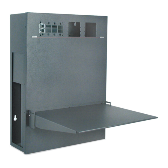
Introduction About the MLM-WB The Extron MLM-WB is a metal wall box for housing a user-supplied MediaLink™ Controller (MLC), a VCR, and up to eight single space Architectural Adapter Plates (AAPs) or AAP devices. You can securely mount a VCR in the wall box, and you select the direction (left or right) the front of the VCR faces. -
Page 7: Chapter 2 • Installation
CAMBOARD Electronics MLM-WB Chapter Two Installation Installation Overview UL Requirements Identifying Included Parts and Hardware Mounting the MLM-WB Installing a VCR Installing the Door Installing AAP Devices and a MediaLink Controller Completing and Testing the Installation Attaching the Shelf www.camboard.de Tel. -
Page 8: Installation Overview
MLM-WB. See “Mounting the MLM-WB” on page 2-5 for details. Install the solid side plate in the unused side of the MLM-WB. Install a VCR in the other side of the MLM-WB. See “Installing a VCR” (page 2-10) in this chapter. -
Page 9: Ul Requirements
UL Requirements The Underwriters Laboratories (UL) requirements listed below pertain to the installation of a MediaLink Controller (MLC) into an MLM-WB wall box. The MLC is not to be connected to a centralized DC power source or used beyond its rated voltage range. -
Page 10: Identifying Included Parts And Hardware
The MLM-WB is shipped partially assembled. You must unfasten and remove some parts before you can mount the enclosure to the wall or install the VCR. Refer to the diagrams below as you unpack the MLM-WB and prepare to install it. Main parts of... -
Page 11: Enclosure Mounting Hardware
#40-343-01 (for shelf) Mounting the MLM-WB The MLM-WB is heavy—about 36 pounds (over 16 kg) without the VCR, MLC, or AAP devices. To avoid back strain during installation, have someone help you unpack the MLM-WB, hold it while you mark screw locations, and help you attach it to the wall. -
Page 12: Installing The Mlm-Wb On A Masonry Wall
Hold the MLM-WB’s outer enclosure against the wall, and use a level tool as a guide for leveling the enclosure. (Lay the level on the top of or on the floor of the enclosure and observe the bubble in the horizontal tube. -
Page 13: Installing The Mlm-Wb On A Non-Masonry Wall
Select a location with adequate clearance for the MLM-WB’s enclosure and for the open door, the extended shelf, and video tape insertion and removal. Locate the wall studs in the area where you will install the MLM-WB, and use a pencil to mark the studs’ locations on the wall. - Page 14 • If two wall studs are accessible where the MLM-WB will be installed, align the mounting holes with the studs, and mark at least six locations for self-tapping metal/wood screws, as shown (as + marks) in the pictures below at left and center.
-
Page 15: Routing Cables Into The Mlm-Wb
Align the slotted mounting holes in the back of the MLM-WB’s outer enclosure with the screws and/or toggle bolts in the wall. Move the MLM-WB forward over the washers and down as shown in step seven of ”Installing the MLM-WB on a masonry wall” on page 2-7. - Page 16 The installer is responsible for providing the conduit and fittings. They are not provided by Extron. If the other hole in the top of the MLM-WB’s outer enclosure will not be used for A/V and control cables, insert an installer-supplied plug into the unused hole.
-
Page 17: Installing A Vcr
The optional VCR will be installed on its side in the bottom portion of the MLM-WB with video tape and front panel access via either the left or right side of the MLM-WB. Follow the procedures below to mount and cable the VCR. - Page 18 The vertical VCR access plate has an L-shaped cross section. Depending on the size of the VCR (i.e., how much depth adjustment is required), attach either the long or the short face of the vertical plate to the MLM-WB enclosure. www.camboard.de Tel.
- Page 19 (5 places) Set the VCR on its side on the VCR shelf so the VCR’s top faces the back of the MLM-WB, and the VCR’s front panel touches the desired side of the MLM-WB. Adjust the size of the side opening in the adjustable...
- Page 20 Depending on which direction the VCR is facing, you may need to move the vertical VCR clamp bracket. The vertical clamp bracket will press against the back of the VCR to hold the VCR snug against the MLM-WB’s side opening. •...
- Page 21 CAMBOARD Electronics Install and adjust the clamp plate assembly. 9a. Place the clamp plate assembly into the MLM-WB enclosure and route the VCR’s power and A/V cables around it, away from the bottom of the VCR, where the clamp plate will go.
-
Page 22: Installing The Door
Installing the Door After the MLM-WB’s enclosure is securely mounted onto the wall and the VCR has been installed inside it, attach the door to the outer enclosure by following these steps: Locate the two nylon shoulder washers, and insert the necks of the washers into the door hinge holes as shown below. -
Page 23: Installing Aap Devices And A Medialink Controller
If the front of the VCR faces out the right side of the MLM-WB, when you open the door, becareful not to push the hinged side of the door against the face of the VCR. -
Page 24: Replacing Mlc Faceplates And Labels, And Mounting The Mlc In The Door
CAMBOARD Electronics Installation, cont’d • Make the cables long enough to allow the MLM-WB’s door to fully open once the MLC is installed in the door. • For connections to control modules that are installed in the MLM-WB’s door, cut... -
Page 25: Completing And Testing The Installation
Repeat steps four through six for each label you wish to replace. Place the plastic window back onto the MLC to cover the labels. Align the openings in the MLM-WB’s door with the MLC’s buttons, knobs, and LEDs, and place the MLC into the door. - Page 26 MLC 206 Power Supply Electrical Power (Use hook-and-loop Source fasteners here.) Close the MLM-WB’s door and secure it to the outer enclosure with the provided flat headed machine screws. L in to p L ap t r o 18 #440 Screws (all around) www.camboard.de...
-
Page 27: Attaching The Shelf
Vertrieb von CAMBOARD Electronics Attaching the Shelf Attach the shelf to the shelf bracket on the MLM-WB’s door. Use the provided #832, ” hex socket screws and #832 nuts, as shown in the following illustration. L in to p... - Page 28 Vertrieb von CAMBOARD Electronics Installation, cont’d www.camboard.de Tel. 07131 911201 ce-info@camboard.de 2-22 MLM-WB • Installation Fax 07131 911203...
- Page 29 Vertrieb von CAMBOARD Electronics MLM-WB A ppendix A Specifications, Part Numbers, Accessories, and Dimensions Specifications Part Numbers and Accessories Dimensions www.camboard.de Tel. 07131 911201 ce-info@camboard.de Fax 07131 911203...
-
Page 30: Appendix A • Specifications, Part Numbers, Accessories, Dimensions
2 gang masonry junction box 980201-1 2 gang junction box cover 980201-2 International junction box mounting plate 991227 Duplex power receptacles (2) 10-513-10 MLM-WB User’s Manual 68-608-01 www.camboard.de Tel. 07131 911201 ce-info@camboard.de MLM-WB • Specifications, Part Numbers, Accessories, and Dimensions Fax 07131 911203... -
Page 31: Accessories
100 feet/30.5 meters long 26-461-02 200 feet/61 meters long 26-461-03 400 feet/122 meters long 26-461-04 Bulk 500 feet/152.4 meters long 22-119-02 Bulk 1000 feet/304.8 meters long 22-119-03 www.camboard.de Tel. 07131 911201 ce-info@camboard.de MLM-WB • Specifications, Part Numbers, Accessories, and Dimensions Fax 07131 911203... -
Page 32: Dimensions
Vertrieb von CAMBOARD Electronics Specifications, Part Numbers, Accessories, Dimensions, cont’d Dimensions www.camboard.de Tel. 07131 911201 ce-info@camboard.de MLM-WB • Specifications, Part Numbers,, Accessories, and Dimensions Fax 07131 911203... - Page 33 CAMBOARD Electronics Extron’s Warranty Extron Electronics warrants this product against defects in materials and workmanship for a period of three years from the date of purchase. In the event of malfunction during the warranty period attributable directly to faulty workmanship and/or materials, Extron Electronics will, at its option,...
- Page 34 PM Industrial Building 3-9-1 Kudan Minami The Netherlands Singapore 368363 Chiyoda-ku, Tokyo 102-0074 Japan 714.491.1500 +31.33.453.4040 +65.6383.4400 +81.3.3511.7655 www.extron.com Fax 714.491.1517 Fax +31.33.453.4050 Fax +65.6383.4664 Fax +81.3.3511.7656 www.camboard.de Tel. 07131 911201 ce-info@camboard.de © 2002 Extron Electronics. All rights reserved. Fax 07131 911203...