Advertisement
Quick Links
Cable Cubby 500 and 700 • Installation Guide
This guide provides instructions for an experienced installer to install and connect the Extron
Cable Cubby 500 and 700 Cable Access Enclosures.
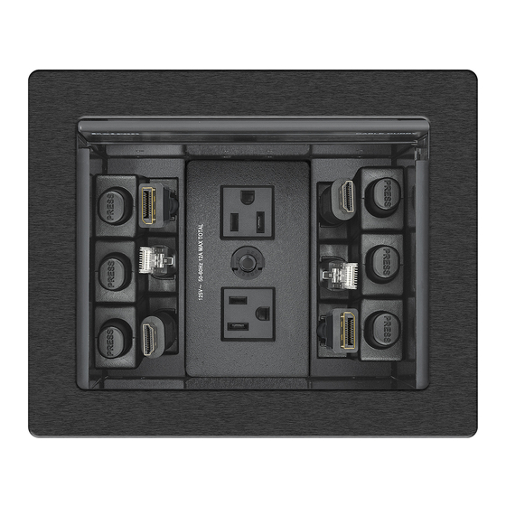
The Cable Cubby units are furniture-mounted enclosures for cable access,
connections, and AC power. Cables that are not in use can be stored out of the
way while remaining connected to the presentation system.
Planning
Check with local and state regulations before starting
the installation:
…
Ensure that the planned installation complies with building and electrical codes.
…
Ensure that the planned installation complies with the Americans with Disabilities Act or
other accessibility requirements.
Check all parts and equipment before installation:
…
Ensure that all parts are present in each kit.
…
Ensure that necessary tools and equipment are available for the installation.
Kit Contents
Cable Cubby 500
le Cubby 500
Zip Ties
Cable Cubby 500
p Ties
Hole Plugs
Connectivity Bracket
i i
B
Zip Ties
e Plugs
Cubby 500
e Cubby 500
#6 Mounting Screws
Tweeker
and Star Washers
Hole Plugs
nting Screws
ar Washers
Ties
p Ties
#4-40 Module Screws
odule Screws
Connectivity Bracket
i i
B
#6 Mounting Screws
Connectivity Bracket
i i
B
and Star Washers
Plugs
e Plugs
Retractor Trim
#4-40 Module Screws
and Screws
Tweeker
Tweeker
ng Screws
ting Screws
Washers
ar Washers
dule Screws
odule Screws
Retractor Trim
Retractor Trim
and Screws
and Screws
Cable Cubby 500
Zip Ties
Cable Cubby 700
Hole Plugs
Cable Cubby 700
Cable Cubby 700
#6 Mounting Screws
and Star Washers
Connectivity Bracket
i i
B
k
Cable Grommet Plate
k
#4-40 Module Screws
Cable Cubby 700
Cable Cubby 700
Tweeker
Cable Cubby 500
Connectivity Bracket
i i
B
k
AAP Frame Plate
Zip Ties
Tweeker
Cable Grommet Plate
Cable Grommet Plate
k
k
Retractor Trim
Cable Cubby 500
and Screws
Hole Plugs
Retractor Pin & Clip
AAP Frame Plate
AAP Frame Plate
Zip Ties
Retractor Trim
#6 Mounting Screws
and Screws
and Star Washers
#4-40 Module Screws
Hole Plugs
Retractor Pin & Clip
Retractor Pin & Clip
#6 Mounting Screws
and Star Washers
#4-40 Module Screws
Cable Cubby 700
Cable Grommet Plate
Connectivity Bracket
i i
B
k
Cable Cubby 500
Cable Cubby 500
Cable Cubby 500
1
Tweeker
Zip Ties
AAP Frame Plate
Zip Ties
Cable Grommet Plate
Connectivity Bracket
Connectivity Bracket
2
Hole Plugs
Hole Plugs
AAP Frame Plate
1
Cable Cubby 700
Retractor Pin & Clip
Tweeker
Cable Grommet Plate
Retractor Trim
and Screws
AC Power Module
#6 Mounting Screws
#6 Mounting Screws
and Star Washers
and Star Washers
1
#4-40 Module Screws
#4-40 Module Screws
AAP Frame Plate
Cable Grommet Plate
Retractor Pin & Clip
Connectivity Bracket
i i
B
k
Retractor Trim
(3) 3/8", (1) 1/4"
Cable Cubby 700
and Screws
AC Power Module
AC Power Module
1 trim, 2 screws
Tweeker
AAP Frame Plate
Retractor Pin & Clip
Cable Grommet Plate
Connectivity Bracket
i i
B
k
1
Retractor Pin & Clip
Retractor Trim
Tweeker
AAP Frame Plate
and Screws
4
Cable Cubby 700
Cable Cubby 700
Cable Cubby 700
2
Cable Grommet Plate
Cable Grommet Plate
i i
B
k
i i
B
k
4
AC Power Module
2
AAP Frame Plate
Tweeker
AAP Frame Plate
2
AC Power Module
Retractor Pin & Clip
(6) 3/8", (2) 1/4"
Retractor Pin & Clip
Retractor Trim
and Screws
2 trims, 4 screws
2
8
AC Power Module
AC Power Mo
AC Pow
AC Power Module
AC Power Module
1
Advertisement

Related Manuals for Extron electronics Cable Cubby 500


Summary of Contents for Extron electronics Cable Cubby 500
- Page 1 Cable Cubby 500 and 700 • Installation Guide This guide provides instructions for an experienced installer to install and connect the Extron Cable Cubby 500 and 700 Cable Access Enclosures. The Cable Cubby units are furniture-mounted enclosures for cable access, connections, and AC power.
- Page 2 Cable Cubby 500 and 700 • Installation Guide (Continued) Preparing the Table Cut a hole in the surface where the enclosure will be installed. Read the following information before making a cut. Determine the best location for the enclosure …...
- Page 3 Preparing the Cable Cubby Step 1 — Assemble the connectivity modules of your choice. Connectivity modules allow you to populate the Cable Cubby with a combination of AAPs, cable pass-through, or retractors. AAP Module Secure the AAP plate on the connectivity brackets, using two of the provided module screws.
- Page 4 Step 2 — Install the modules. Determine where the connectivity modules and power module will be installed in the Cable Cubby. The modules may be installed on the left or right side of the enclosure and at various heights. NOTE: •...
- Page 5 Cable Cubby 500 and 700 • Installation Guide (Continued) Step 2 — Under the table, adjust the side clamps on the enclosure. NOTE: To lower the side clamp, turn the lever down, then press and hold the locking plate while sliding down the clamp.
-
Page 6: Installation Checklist
(Inside India Only) Extron USA - West Extron USA - East +1.714.491.1500 +1.919.850.1000 +31.33.453.4040 +91.80.3055.3777 +1.714.491.1517 FAX +1.919.850.1001 FAX +31.33.453.4050 FAX +91.80.3055.3737 FAX © www.extron.com 2014 Extron Electronics All rights reserved. All trademarks mentioned are the property of their respective owners.
Need help?
Do you have a question about the Cable Cubby 500 and is the answer not in the manual?
Questions and answers