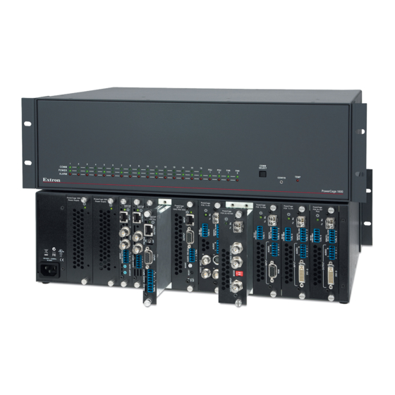
Extron electronics PowerCage 1600 User Manual
Modular power enclosure for fiber optic and twisted pair extenders
Hide thumbs
Also See for PowerCage 1600:
- Setup manual (2 pages) ,
- Setup manual (29 pages) ,
- User manual (22 pages)
Table of Contents
Advertisement
Quick Links
Download this manual
See also:
Setup Manual
Advertisement
Table of Contents

Related Manuals for Extron electronics PowerCage 1600


Summary of Contents for Extron electronics PowerCage 1600
- Page 1 User Guide Fiber Optic Products PowerCage 1600 Enclosure ™ Modular Power Enclosure for Fiber Optic and Twisted Pair Extenders 68-1717-01 Rev. C 02 12...
- Page 2 Safety Instructions • English Warning Power sources • This equipment should be operated only from the power source indicated on the product. This This symbol is intended to alert the user of important operating and mainte- equipment is intended to be used with a main power system with a grounded (neutral) conductor. The third nance (servicing) instructions in the literature provided with the equipment.
- Page 3 FCC Class A Notice This equipment has been tested and found to comply with the limits for a Class A digital device, pursuant to part 15 of the FCC Rules. Operation is subject to the following two conditions: This device may not cause harmful interference. This device must accept any interference received, including interference that may cause undesired operation.
- Page 4 TIP: A tip provides a suggestion to make working with the application easier. WARNING: A warning warns of things or actions that might cause injury, death, or other severe consequences. Copyright © 2012 Extron Electronics. All rights reserved. Trademarks All trademarks mentioned in this guide are the properties of their respective owners.
-
Page 5: Table Of Contents
Optional Accessories ........22 Installing Transmitter and Receiver Boards into the Enclosure ............6 Index ..............24 Mounting the Unit ..........7 UL Guidelines for Rack Mounting ....7 Rack Mounting ..........7 Cabling and Testing ..........8 PowerCage 1600 Enclosure • Contents... - Page 6 PowerCage 1600 Enclosure • Contents...
-
Page 7: Introduction
Introduction This guide describes the Extron PowerCage 1600 Modular Power Enclosure and how to install, configure, and operate the enclosure and its optional transmitter and receiver boards. Throughout this guide “PowerCage” and “the enclosure” refer to the PowerCage 1600 Enclosure. -
Page 8: Powercage Fox Fiber Optic Extender Boards
Audio or RS-232 with Skew Equalization PowerCage MTP T AV — MTP Twisted Pair Transmitter for Composite or S-video and Audio PowerCage MTP R AV — MTP Twisted Pair Receiver for Composite or S-video and Audio PowerCage 1600 Enclosure • Introduction... -
Page 9: System Example
System Example The following diagram shows a typical PowerCage 1600 system installation. Building 1 MVX 168 VGA A INPUTS Rackmount PCs MTP R 15HD RSA D Receivers CONTROL CONFIG ENTER PRESET VIEW VIDEO AUDIO Satellite Receivers OUTPUTS MVX SERIES Flat Panel Displays VGA MATRIX SWITCHER ADPS™... -
Page 10: Installation
Heed the following safety information when installing or servicing the PowerCage system: CAUTION: The PowerCage uses double pole/neutral fusing. Power must be disconnected before servicing internal components. Do not leave empty board slots open or uncovered while the unit is powered on. PowerCage 1600 Enclosure • Installation... -
Page 11: Enclosure And Rear Panel Features
(standard) (optional) 8 double-slot optional boards) Figure 3. The Rear Panel of the PowerCage 1600 Enclosure Power connector — Connect this port to a 110-240 VAC, 50-60 Hz power source using a standard IEC power cord. NOTE: The power supplies and transmitter and receiver boards may be installed or replaced before or after the unit is powered on. -
Page 12: Installing Transmitter And Receiver Boards Into The Enclosure
Tighten the screws to secure the board in place. NOTE: Use a tool to fully tighten the screws after initial installation and subsequent removal and replacement of the boards. Repeat steps 2 and 3 for all boards needing installation. PowerCage 1600 Enclosure • Installation... -
Page 13: Mounting The Unit
Fasten the brackets to the rack. /6 0H 0- 24 M AX 3-U Rack Mount Bracket (use four mounting holes) Figure 5. Attaching Brackets and Rack Mounting the Enclosure PowerCage 1600 Enclosure • Installation... -
Page 14: Cabling And Testing
Some fiber optic boards include pass-through RS-232 connections. Some boards have mode switches. Some MTP twisted pair boards include picture adjustment or peaking controls. PowerCage 1600 Enclosure • Installation... -
Page 15: Operation
Communicating with the Boards: Making an RS-232 Connection Front Panel Features The front panel of the PowerCage 1600 Enclosure provides a variety of light emitting diode (LED) status indicators, a selection button, and a port for communicating with an active installed board. - Page 16 (approximately 167 °F [75°C]) and equipment damage is imminent. If the Temp LED lights, power down the unit, ensure adequate ventilation, and allow the PowerCage system to cool before restoring power. PowerCage 1600 Enclosure • Operation...
-
Page 17: Communicating With The Boards: Making An Rs-232 Connection
Use a terminal emulation program such as Telnet or Extron DataViewer to send Simple Instruction Set (SIS) commands and queries to the selected board. For model-specific commands and adjustments, refer to the user guide for each model of board that is installed in the PowerCage Enclosure. PowerCage 1600 Enclosure • Operation... -
Page 18: Specifications And Part Numbers
Multimode ....... 7 dB, maximum Maximum channel data rate PowerCage FOX AV boards ..2.125 Gbps PowerCage FOX HDMI boards . 4.95 Gbps (1.65 Gbps per color) Other PowerCage FOX boards . 4.25 Gbps PowerCage 1600 Enclosure • Specifications and Part Numbers... - Page 19 1920x1200 @ 60 Hz, undersampled PowerCage FOX Tx/Rx DVI Plus Up to 1920x1200 or 1080p @ 60 Hz pixel for pixel Formats .......... RGB and YCbCr digital video Standards ........DVI 1.0, HDMI PowerCage 1600 Enclosure • Specifications and Part Numbers...
- Page 20 Nominal level ......... 0.8 Vp-p Minimum/maximum levels ....0.5 V to 1.0 Vp-p Impedance ........75 ohms Return loss ........<-25 dB @ 100 MHz DC offset ........±5 mV with input at 0 offset PowerCage 1600 Enclosure • Specifications and Part Numbers...
- Page 21 Connectors ........1 female 19-pin HDMI type A Video — PowerCage MTP T 15HD RSA, PowerCage MTP R 15HD RSA SEQ Gain ..........Unity Number/signal type ......1 set of proprietary analog signals Connector ........1 female RJ-45 PowerCage 1600 Enclosure • Specifications and Part Numbers...
- Page 22 0.3 Vp-p for C of S-video Minimum/maximum levels ....0.3 V to 1.5 Vp-p with no offset Impedance ........75 ohms Return loss ........<-30 dB, DC @ 10 MHz DC offset (max. allowable) ..... 250 mV PowerCage 1600 Enclosure • Specifications and Part Numbers...
- Page 23 Nominal levels ........ +4 dBu (1.23 Vrms), -10 dBV (316 mVrms) Maximum level ....... +17 dBV, unbalanced at 1% THD+N NOTE: 0 dBu = 0.775 Vrms, 0 dBV = 1 Vrms, 0 dBV ≈ 2 dBu PowerCage 1600 Enclosure • Specifications and Part Numbers...
- Page 24 Nominal levels ........ +4 dBu (1.23 Vrms), -10 dBV (316 mVrms) Maximum level ....... +18 dBu, (unbalanced) at 1% THD+N NOTE: 0 dBu = 0.775 Vrms, 0 dBV = 1 Vrms, 0 dBV ≈ 2 dBu PowerCage 1600 Enclosure • Specifications and Part Numbers...
- Page 25 Impedance ........50 ohms unbalanced, 100 ohms balanced Gain error ........±1 dB channel to channel Nominal levels ........ +4 dBu (1.23 Vrms), -10 dBV (316 mVrms) Maximum level ....... +18 dBu, unbalanced at 1% THD+N PowerCage 1600 Enclosure • Specifications and Part Numbers...
- Page 26 Recommended cable type ....For PowerCage MTP boards: Extron Enhanced Skew-Free AV UTP cable or ™ CAT 5/5e/6 (shielded or unshielded) Power supply ........Internal* 100-240 VAC, 50-60 Hz; 1 or 2* (positive-negative) hot-swappable power supplies A redundant power supply is optional. PowerCage 1600 Enclosure • Specifications and Part Numbers...
- Page 27 EMI/EMC ......... CE, C-tick, FCC Class A, ICES, VCCI MTBF ..........30,000 hours Warranty ........3 years parts and labor NOTE: All nominal levels are at ±10%. NOTE: Specifications are subject to change without notice. 8.0-022112-D9 PowerCage 1600 Enclosure • Specifications and Part Numbers...
-
Page 28: Part Numbers
Part Numbers Included Parts The following items are included with the PowerCage 1600 Modular Power Enclosure: Included Parts Replacement Part Number PowerCage 1600 Enclosure (3U, 16-slot frame) 60-978-01 Rack mounting brackets Blank slot covers: 1 single slot, 7 dual slot, 1 power supply cover... - Page 29 Twisted pair transmitter for composite or S-video and audio PowerCage MTP R AV 70-816-01 Twisted pair receiver for composite or S-video and audio Cables Part Number 9-pin D female to 2.5 mm TRS configuration cable 70-335-01 PowerCage 1600 Enclosure • Specifications and Part Numbers...
-
Page 30: Index
9 FOX 500 Series redundant power supply compatibility with 2 part number 22 FOXBOX cable type part number, hot swappability 2 compatibility with 2 for MTP boards 2 slot locations 5 cabling and testing 8 PowerCage 1600 Enclosure • Index... - Page 31 RS-232 control and configuration. location and numbering 5 See also communication selection space (Comm Select) button amount required for air Config port pin configuration 10 circulation 7 RS-232 protocol 10 setting up communication with the boards 11 PowerCage 1600 Enclosure • Index...
- Page 32 Extron Electronics makes no further warranties either expressed or implied with respect to the product and its quality, performance, merchantability, or fitness for any particular use. In no event will Extron Electronics be liable for direct, indirect, or consequential damages resulting from any defect in this product even if Extron Electronics has been advised of such damage.
Need help?
Do you have a question about the PowerCage 1600 and is the answer not in the manual?
Questions and answers