Advertisement
Quick Links
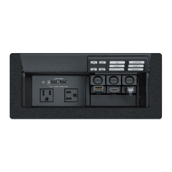
EBP 1200C Cable Cubby Enclosure
with eBUS
Button Panel • Setup Guide
®
The Extron EBP 1200C is a Cable Cubby
integrated eBUS button panel to combine convenient
AV and data connectivity with a fully customizable AV
system control interface for use with Extron IPCP Pro
Series Control Processors.
NOTE:
These products are only for use with Extron
UL Listed IPCP Pro control processors.
This guide provides basic instructions for an
experienced installer to install an EBP 1200C Cable
Cubby button panel:
Setup Checklist
•
Installing the EBP 1200C Cable Cubby
•
Connecting to the eBUS System
•
For more details on eBUS, see the eBUS Technology
Reference Guide, available on www.extron.com. For
details on configuration, see the software help files.
Setup Checklist
Step 1 — Planning
…
Download and install the latest version of the software, firmware, and device drivers needed to configure the IPCP Pro
and control the connected AV products. See the IPCP Pro Series User Guide (available at www.extron.com) for details on
software and drivers.
…
Obtain network information (IP addresses, passwords, DHCP settings, and the like) and the MAC address for the control
processor.
…
Obtain model names, drivers, and setup information for AV devices.
…
Determine which eBUS cabling topologies to use and obtain cables, mounting hardware, and any power supplies or hubs
required by that configuration.
…
Make sure you are familiar with all the
Cable Cubby.
…
Before cutting a hole in any furniture, select the best location for the EBP 1200C.
Ensure that the product is oriented so that the lid opens in the desired direction.
•
Ensure there is enough space for all the system cables and components, including cable retractors, if they are to be
•
installed.
Check all relevant regulations
…
Step 2 — Cutting the Table
…
Decide on the method for cutting a hole in the table (see
…
Verify that you have the correct cut-out template and dimensions (see
Step 3 — Setting the eBUS ID Address
…
All eBUS devices connected to the same control processor must have a unique eBUS ID address. This requires access to the
DIP switches on the bottom panel of the EBP 1200C and it is more convenient to set the address before the EBP 1200C is
installed in the table (see
1200 with an
®
Display with Speakers
MODEL 80
Figure 1.
Included parts
(see the next page).
Setting the eBUS ID Address
Computer
HDMI
FLAT PANEL
Ethernet
HDMI
TCP/IP
Network
Ethernet
EBP 1200C Application Diagram
(see the next page) and have all the necessary tools for installing the
Cutting the Table
on page 3).
Cutting the Table
on page 10).
Product Category
Laptop
Laptop
VGA
HDMI
Extron
EBP 1200C
Cable Cubby eBUS
Button Panel
ON
OFF
PC
HDMI
LAPTOP
VGA
MUTE
AUX VIDEO
Extron
RS-232
COM 1
COM 2
100-240V ~ --A MAX
OUT
1
2
3
4 +V
1 CONFIGURABLE
2
HDMI
3
HDMI
TALLY OUT
Tx Rx
G
RTS CTS
Tx Rx
G
HDMI
L
R
POWER
VOL
RELAYS
IN
L
R
CONTACT IN
RS-232
12V
1
2
--A MAX
V C G
1
2
C
4
HDMI
1
2
3
4 G
Tx Rx G
INPUT
AUDIO
OUTPUT
REMOTE
50-60 Hz
Extron
IPCP Pro 250
Extron
IP Link Pro
IN1604 HD
Control Processor
Four Input Scaler
on page 3).
eBUS
DIGITAL I/O
IPCP PRO 250
1
2
3
4
G
eBUS
IR/S
+ V + S - S G
PWR OUT = 6W
S
G
LAN
1
Advertisement

Subscribe to Our Youtube Channel
Related Manuals for Extron electronics EBP 1200C


Summary of Contents for Extron electronics EBP 1200C
- Page 1 All eBUS devices connected to the same control processor must have a unique eBUS ID address. This requires access to the DIP switches on the bottom panel of the EBP 1200C and it is more convenient to set the address before the EBP 1200C is...
-
Page 2: Table Of Contents
Step 5 — Changing the Buttons … The EBP 1200C ships with a set of buttons installed and some additional blank buttons ship with the unit. You can order others from www.extron.com. To replace one or more of the individual buttons, see... - Page 3 Product Category Installing the EBP 1200C Cable Cubby Cutting the Table CAUTION: Wear safety glasses when operating power equipment. Failure to comply can result in eye injury. ATTENTION : Portez des lunettes de sécurité lorsque vous utilisez l’équipement électrique. Ne pas respecter cela peut conduire à...
-
Page 4: Ebp 1200C
Assemble the Connectivity Modules of your Choice The EBP 1200C is provided with a single connectivity bracket that can be used with either the AAP frame plate or the cable grommet plate. Follow the steps below to assemble the connectivity modules of your choice before they can be mounted into the EBP 1200C. -
Page 5: Retractor Bracket
Product Category Retractor bracket Use the retractor bracket to mount retractors in the Cable Cubby enclosure. The retractor bracket accommodates up to three Retractor Series/2 or Retractor Series/2 XL cable retraction modules. The retractors must be purchased separately. If you require retractors, insert the retractor bracket as shown in figure 5. - Page 6 EBP 1200C • Setup Guide (Continued) Mount the EBP 1200C TIP: Before mounting the EBP 1200C, you should set the eBUS ID address, since this requires access to the DIP switches, which are on the bottom of the unit (see Setting the eBUS ID Address on page 10).
- Page 7 Product Category Install the Retractors Retractors can be installed in a vertical, angular, or horizontal orientation. No adjustment of the enclosure screws is needed if the retractors are mounted vertically. To mount at an angle or horizontally, adjust the enclosure screws as shown below. When the retractors are mounted horizontally, the retractor mechanism must be secured to the underside of the table (see Cable Retractor Setup Guide, which is available at www.extron.com).
- Page 8 Connecting to the eBUS System The EBP 1200C has two eBUS ports that support power and communication with an IPCP Pro control processor. Up to eight eBUS endpoint devices such as EBP button panels can be connected to the control processor and to each other in various cabling topologies.
-
Page 9: Changing Buttons
Product Category Changing Buttons You can replace a faceplate or one or more of the individual buttons. Some additional blank buttons ship with the unit. You can order standard or custom buttons from www.extron.com. To change the buttons: Insert the Extron removal tool into one of the removal 2 2 3 3 slots in the top edge of the button panel. - Page 10 000011 NOTES: 1 2 3 4 5 6 • By factory default, the EBP 1200C is set to BUS ID address 26 (binary: 011010), as shown in the 000100 diagram below. •...
- Page 11 Product Category Cable All Devices Attach cables using the diagrams in this section as a guide. Connect a 4-pole captive screw connector to each end of the cable, wiring both ends as shown in figure 15. In most cases the EBPs are powered by the IPCP Pro control processor that provides the eBUS signal.
- Page 12 EBP 1200C • Setup Guide (Continued) EBPs that are relatively far from the control processor (see the eBUS Technology Reference Guide on www.extron.com details) can be connected to an optional Extron PS 1220EB eBUS power inserter, or an Extron 12 VDC desktop power supply as shown in the following diagrams.
-
Page 13: Configure The System
Product Category Configure the System NOTE: EBPs are shipped with pre-labelled buttons in place but these buttons do not have any functions associated with them until they are configured with Global Configurator or programmed with Global Scripter. See the Global Configurator Help File or Global Scripter Help File as needed for step-by-step instructions and detailed information. - Page 14 +86.21.3760.1566 FAX +971.4.299.1880 FAX +61.8.8351.2511 FAX +31.33.453.4040 +91.80.3055.3777 +1.714.491.1500 +1.919.850.1000 +31.33.453.4050 FAX +91.80.3055.3737 FAX +1.714.491.1517 FAX +1.919.850.1001 FAX © 2017 Extron Electronics All rights reserved. All trademarks mentioned are the property of their respective owners. www.extron.com 68-1449-52 Rev. A 05 17...
Need help?
Do you have a question about the EBP 1200C and is the answer not in the manual?
Questions and answers