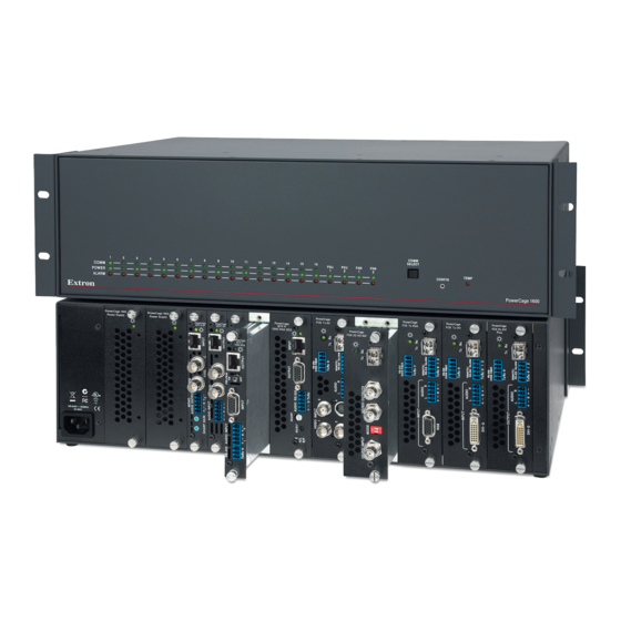
Extron electronics PowerCage 1600 User Manual
Modular power enclosure for fiber optic and twisted pair extenders
Hide thumbs
Also See for PowerCage 1600:
- Setup manual (2 pages) ,
- User manual (32 pages) ,
- Setup manual (29 pages)

Related Manuals for Extron electronics PowerCage 1600


Summary of Contents for Extron electronics PowerCage 1600
- Page 1 User Guide Fiber Optic Products PowerCage 1600 Enclosure Modular Power Enclosure for Fiber Optic and Twisted Pair Extenders 68-1717-01 Rev. E 01 19...
- Page 2 Safety Instructions Safety Instructions • English Istruzioni di sicurezza • Italiano WARNING: This symbol, , when used on the product, is intended to AVVERTENZA: Il simbolo, , se usato sul prodotto, serve ad alert the user of the presence of uninsulated dangerous voltage within avvertire l’utente della presenza di tensione non isolata pericolosa the product’s enclosure that may present a risk of electric shock.
- Page 3 ついては、 エクス トロンのウェブサイ ト より 『Extron Safety www.extron.com and Regulatory Compliance Guide』 (P/N 68-290-01) をご覧ください。 Copyright © 2017-2019 Extron Electronics. All rights reserved. Trademarks All trademarks mentioned in this guide are the properties of their respective owners. The following registered trademarks ®...
- Page 4 ATTENTION : Risque de blessure mineure. ATTENTION: • Risk of property damage. • Risque de dommages matériels. NOTE: A note draws attention to important information. Specifications Availability Product specifications are available on the Extron website, www.extron.com. PowerCage 1600 Enclosure User Guide • Conventions...
-
Page 5: Table Of Contents
Mounting the Unit ..........10 UL Guidelines for Rack Mounting ....10 Rack Mounting ..........10 Cabling and Testing .......... 11 Operation .............. 12 Front Panel Features ......... 12 Communicating with the Boards: Making an RS-232 Connection ......... 14 PowerCage 1600 Enclosure • Contents... - Page 6 PowerCage 1600 Enclosure • Contents...
-
Page 7: Introduction
Introduction This guide describes the Extron PowerCage 1600 Modular Power Enclosure and how to install, configure, and operate the enclosure and its optional transmitter and receiver boards. This section of the guide covers the following topics: • About this Guide •... -
Page 8: Features
Features PowerCage Enclosure and System • Versatile input-output options — The PowerCage 1600 accommodates up to 16 single-slot or 8 double-slot FOX fiber optic boards and MTP twisted pair boards. • 3U, rack-mountable enclosure — The enclosure streamlines installation and eliminates individual power supplies for each transmitter and receiver. -
Page 9: Powercage Mtp Twisted Pair Boards
Audio or RS-232 with Skew Equalization PowerCage MTP T AV — MTP Twisted Pair Transmitter for Composite or S-video • and Audio PowerCage MTP R AV — MTP Twisted Pair Receiver for Composite or S-video and • Audio PowerCage 1600 Enclosure • Introduction... -
Page 10: System Example
System Example The following diagram shows a typical PowerCage 1600 system installation. Building 1 MVX 168 VGA A INPUTS Rackmount PCs MTP R 15HD RSA D Receivers CONTROL CONFIG ENTER PRESET VIEW VIDEO AUDIO Satellite Receivers OUTPUTS MVX SERIES Flat Panel Displays... -
Page 11: Installation
• Do not leave empty board slots open or uncovered while the unit is powered on. • Les emplacements de cartes vides ne doivent pas être laissés ouverts ou découverts lorsque l’unité est en marche. PowerCage 1600 Enclosure • Installation... -
Page 12: Enclosure And Rear Panel Features
(standard) (optional) optional boards) Figure 3. The Rear Panel of the PowerCage 1600 Enclosure Power connector — Connect this port to a 110-240 VAC, 50-60 Hz power source using a standard IEC power cord. NOTE: The power supplies and transmitter and receiver boards may be installed or replaced before or after the unit is powered on. - Page 13 NOTES: • Cover all empty board slots; do not leave them open. Securely fasten the screws for boards and blank panels. • A double-slot board connects to the lower-numbered slot. PowerCage 1600 Enclosure • Installation...
-
Page 14: Installing Transmitter And Receiver Boards Into The Enclosure
Where applicable, remove as many blank plates or previously installed boards from the rear of the PowerCage Enclosure as necessary to accommodate the number of new boards to be installed. Save the screws for use in step 3. PowerCage 1600 Enclosure • Installation... - Page 15 Tighten the screws to secure the board in place. NOTE: Use a tool to fully tighten the screws after initial installation and subsequent removal and replacement of the boards. Repeat steps 2 and 3 for all boards needing installation. PowerCage 1600 Enclosure • Installation...
-
Page 16: Mounting The Unit
To rack mount the enclosure: Attach the mounting brackets to the sides of the enclosure, as shown in figure 6. The brackets can be attached at either the front or the back. Fasten the brackets to the rack. PowerCage 1600 Enclosure • Installation... -
Page 17: Cabling And Testing
• Some fiber optic boards include pass-through RS-232 connections. • Some boards have mode switches. • Some MTP twisted pair boards include picture adjustment or peaking controls. PowerCage 1600 Enclosure • Installation... -
Page 18: Operation
Communicating with the Boards: Making an RS-232 Connection Front Panel Features The front panel of the PowerCage 1600 Enclosure provides a variety of LED status indicators, a selection button, and a port for communicating with an active installed board. See the diagram below and the following descriptions for details. - Page 19 Sleeve (Gnd) 9-pin D Connection TRS Plug Pin 2 Computer's Rx line Pin 3 Computer's Tx line Ring Pin 5 Computer's signal ground Sleeve Figure 8. 9-pin D to 2.5 mm Stereo Mini TRS RS-232 Cable PowerCage 1600 Enclosure • Operation...
-
Page 20: Communicating With The Boards: Making An Rs-232 Connection
(The next slot may not be numbered contiguously with the previously selected board.) PowerCage 1600 Enclosure • Operation... - Page 21 Use a terminal emulation program such as Telnet or Extron DataViewer to send Simple Instruction Set (SIS) commands and queries to the selected board. For model-specific commands and adjustments, refer to the user guide for each model of board that is installed in the PowerCage Enclosure. PowerCage 1600 Enclosure • Operation...
- Page 22 Extron Electronics makes no further warranties either expressed or implied with respect to the product and its quality, performance, merchantability, or fitness for any particular use. In no event will Extron Electronics be liable for direct, indirect, or consequential damages resulting from any defect in this product even if Extron Electronics has been advised of such damage.
Need help?
Do you have a question about the PowerCage 1600 and is the answer not in the manual?
Questions and answers