Extron electronics PowerCage 1600 Setup Manual
Powercage 1600 enclosure setup guide
Hide thumbs
Also See for PowerCage 1600:
- User manual (32 pages) ,
- Setup manual (29 pages) ,
- User manual (22 pages)
Advertisement
Quick Links
PowerCage 1600 Enclosure • Setup Guide
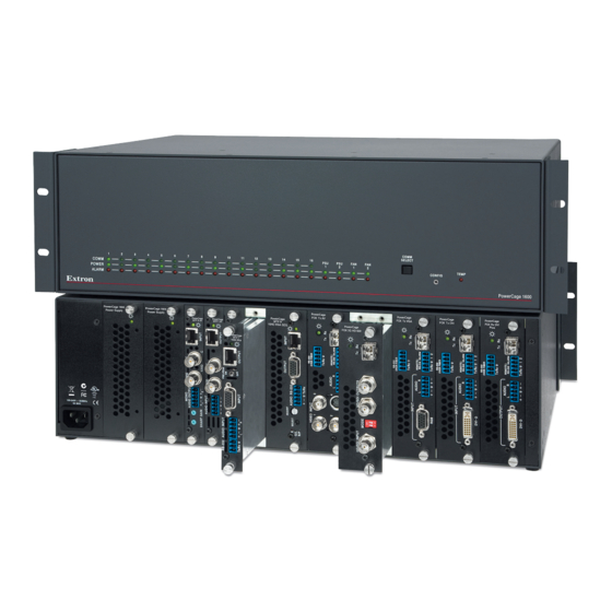
The Extron
PowerCage 1600 is a rack-mountable, 16-slot enclosure with vents, fans, an
®
integrated power supply, and optional redundant power supply that supports PowerCage
transmitter and receiver boards. PowerCage fiber optic (FOX) boards and PowerCage
twisted pair (MTP) boards are mounted within the PowerCage Enclosure and can be used
in any combination. Each optional board operates independently of the others, creating an
integrated system of individual transmitters and receivers, not a matrixed system.
Rear Panel
PowerCage 1600
PowerCage 1600
Power Supply
Power Supply
Power
Power
Supply
Supply
1
2
N15778
I.T.E.
1T23
100-240V
50/60Hz
5A MAX.
Power
Main
Slot for
Connector
Power
Redundant
Supply
Power Supply
(standard)
(optional)
Heed the following safety information when installing or servicing the PowerCage system:
CAUTION:
The PowerCage uses double pole/neutral fusing. Power must be disconnected before servicing internal
components. Do not leave empty board slots open or uncovered while the unit is powered on.
Installation
Step 1: Install the redundant power supply and transmitter and receiver boards.
Refer to the model-specific guide for each PowerCage transmitter and receiver board you are installing. Some boards have
switches that must be set before installation. The guides describe the features of each board and how to set up and cable it.
NOTES
: The boards are hot-swappable; they can be installed or removed without turning off or disconnecting the
power to the PowerCage Enclosure. Use ESD precautions when installing a board to avoid damaging it. Keep
the board in the anti-static bag until it is needed. Use proper grounding techniques during installation.
a.
Remove as many blank plates or previously installed boards from the
rear of the PowerCage Enclosure as necessary for the number of
new boards to be installed. Save the screws for use in step 3.
b.
Hold the board with the signal connectors towards
you and the LED at the top, and align the top and
bottom grooves of the board with the slide
posts in the selected enclosure slot. See
the figure at right.
c.
Carefully slide the board into the slot,
aligning the two tabs on the lower
front end of the board with the
matching ports in the enclosure.
Push the board firmly into place.
Tighten the screws to secure the board
in place.
d.
Repeat steps b and c for all boards
needing installation.
NOTE:
Use a tool to fully tighten the screws after
initial installation and subsequent removal
and replacement of the boards.
e.
If desired, connect power to the enclosure and verify that the fans, boards, and LEDs power up correctly; then
disconnect power.
Slot Numbers
16
15
14
13
12
11
10
9
Slots for Transmitter and Receiver Boards
(up to 16 single-slot or 8 double-slot optional boards)
8
7
6
5
4
3
2
1
FO
U S
C
ED
LI ST
8
23
N 15
77
1T
.E .
I.T
z
/6 0H
50
0V
.
0- 24
M AX
10
5A
Figure 1.
Inserting Boards into the PowerCage Enclosure
NOTES: The front panel
board status LED
numbers correspond to
the slot numbers.
Cover all empty board
slots; DO NOT leave them
open. Securely fasten the
retaining screws for
boards and blank panels.
Ca
ge
w er
R AV
Po
M TP
e
C ag
D I
w er
H D
-S
Po
X 3G
FO
e
C ag
R G
B
w er
Po
R X
X 4G
Align board and
slide into slot.
e
C ag
R G
B
w er
R X
Po
X 4G
FO
(Continued on page 2)
Screws
(2 per
board)
1
Advertisement

Subscribe to Our Youtube Channel
Related Manuals for Extron electronics PowerCage 1600


Summary of Contents for Extron electronics PowerCage 1600
- Page 1 PowerCage 1600 Enclosure • Setup Guide The Extron PowerCage 1600 is a rack-mountable, 16-slot enclosure with vents, fans, an ® integrated power supply, and optional redundant power supply that supports PowerCage transmitter and receiver boards. PowerCage fiber optic (FOX) boards and PowerCage twisted pair (MTP) boards are mounted within the PowerCage Enclosure and can be used in any combination.
- Page 2 PowerCage 1600 Enclosure • Setup Guide (Continued) Step 2: Mount the enclosure to an equipment rack. Attach the included mounting brackets to the sides of the enclosure, then fasten the brackets to the rack. The brackets can be attached at either the front or the back.
Need help?
Do you have a question about the PowerCage 1600 and is the answer not in the manual?
Questions and answers